US4676601A - Drive apparatus for a liquid crystal dazzle-free mirror arrangement - Google Patents
Drive apparatus for a liquid crystal dazzle-free mirror arrangement Download PDFInfo
- Publication number
- US4676601A US4676601A US06/847,142 US84714286A US4676601A US 4676601 A US4676601 A US 4676601A US 84714286 A US84714286 A US 84714286A US 4676601 A US4676601 A US 4676601A
- Authority
- US
- United States
- Prior art keywords
- dazzlement
- light
- mirror assembly
- view mirror
- ambient light
- Prior art date
- Legal status (The legal status is an assumption and is not a legal conclusion. Google has not performed a legal analysis and makes no representation as to the accuracy of the status listed.)
- Expired - Fee Related
Links
Images


Classifications
-
- B—PERFORMING OPERATIONS; TRANSPORTING
- B60—VEHICLES IN GENERAL
- B60R—VEHICLES, VEHICLE FITTINGS, OR VEHICLE PARTS, NOT OTHERWISE PROVIDED FOR
- B60R1/00—Optical viewing arrangements; Real-time viewing arrangements for drivers or passengers using optical image capturing systems, e.g. cameras or video systems specially adapted for use in or on vehicles
- B60R1/02—Rear-view mirror arrangements
- B60R1/08—Rear-view mirror arrangements involving special optical features, e.g. avoiding blind spots, e.g. convex mirrors; Side-by-side associations of rear-view and other mirrors
- B60R1/083—Anti-glare mirrors, e.g. "day-night" mirrors
- B60R1/088—Anti-glare mirrors, e.g. "day-night" mirrors using a cell of electrically changeable optical characteristic, e.g. liquid-crystal or electrochromic mirrors
Definitions
- the invention relates to reflecting mirror arrangements. More particularly, the invention provides a reflecting mirror arrangement of the dazzlement preventing type using a liquid crystal panel.
- a drive apparatus detects light incident to the reflecting mirror using a light sensor installed near the reflecting mirror and drives the liquid crystal panel to be made opaque when intensity of the incident light, for example, light rays from a head light of a succeeding vehicle, is greater than a prescribed value and thus provides the dazzlement preventing state to the reflecting mirror.
- Known reflecting mirrors of the dazzlement preventing type have disadvantages in that even when ambient region is in ordinary brightness during daytime the light sensor detects the brightness and the drive apparatus operates to cause the reflecting mirror to operate in the dazzlement preventing state even though the user does not feel dazzlement. Therefore a switch for the drive apparatus must be turned off during daytime.
- An object of the invention is to provide a drive apparatus for a reflecting mirror of the dazzlement preventing type using liquid crystal wherein when light rays from a headlight of a following car, from which one would feel dazzlement at night, are projected onto the reflecting mirror, the drive apparatus operates to put the reflecting mirror in the dazzlement preventing state and in case of the ordinary brightness of the light rays during daytime does not operate in the dazzlement preventing state.
- a further object of the invention is to provide a drive apparatus for a reflecting mirror of the dazzlement preventing type using a liquid crystal which detects the intensity of the light rays and which, corresponding to the result of detection, even during daytime, operates the mirror in the dazzlement preventing state.
- a related object of the invention is to provide a drive apparatus having a improved reflecting mirror, the glass surface of which is covered by a tansparent plastic film, so that even in case of strong impact force on, the glass is not broken away.
- a drive apparatus for a reflecting mirror of the dazzlement preventing type using a liquid crystal comprising an incident light detecting unit for detecting incident light onto the reflecting mirror and outputting an incident light electrical signal indicative of illuminance of the incident light.
- Am ambient light detecting unit detects brightness around the reflecting mirror and produces an ambient light signal indicative of the illuminance around the reflecting mirror.
- a control unit receives both the incident light signal and ambient light signal and provides a control signal to drive the liquid crystal panel when the illuminance on the mirror surface caused by incident light is greater than a predetermined value and the illuminance around the mirror is less than a predetermined value of ambient light illuminance.
- a drive unit receives the control signal and applies an electric field between two electrods of the liquid crystal panel in response to the control signal for driving the liquid crystal panel.
- FIG. 1 is a block diagram of the invention
- FIG. 2 is a front view of a reflecting mirror of the dazzlement preventing type driven by apparatus of a first embodiment of the invention
- FIG. 3 is a side view of the mirror of FIG. 2;
- FIG. 4 is an electric circuit diagram of the apparatus of the first embodiment of the invention.
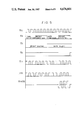
- FIG. 5 is a timing chart illustrating the operation of the circuit shown in FIG. 4;
- FIG. 6 is an electric circuit diagram of the apparatus of a second embodiment of the invention.
- FIG. 7 is a timing chart illustrating the operation of the circuit shown in FIG. 6;
- FIG. 8 is an electric circuit diagram of an apparatus of a third embodiment of the invention.
- FIG. 9 is a timing chart illustrating the operation of the circuit shown in FIG. 8.
- FIG. 10 is a detailed side view of the reflecting mirror shown in FIGS. 2, 3 as an embodiment of the present invention.
- FIG. 1 there is shown a block diagram of the invention.
- this invention is particularly applicable to the rear view mirror of an automobile.
- the invention is not limited to such use, but rather has more general application to other mirror arrangement wherever it is appreciate to present dazzlement.
- An incident light detecting unit 4 detects incident light projected onto the reflecting mirror from a front side thereof using a light sensor and produces an electrical incident light signal indicative of the illuminance (brightness) of that incident light.
- the front side of the reflecting mirror is the side of the mirror on which incident light impinges.
- Incident light includes light rays from a headlight of a succeeding (following) vehicle or direct solar rays projected from the rear of an automobile.
- Any light sensor may be used as long as it can convert the incident light into an electric signal.
- a photo-conductive cell or a photo-diode may be used for that purpose and located where desired to detect incident light to the reflecting mirror, e.g. lower portion at front side of the reflecting mirror.
- An ambient light detecting unit 5 detects brightness in a region around the reflecting mirror and output illuminance in the ambient region and provides an electric ambient brightness signal indicative thereof.
- Iluminance in the ambient region means illuminance in a region near the reflecting mirror caused by light (ambient light) other than the incident light.
- illuminance at near surface of the reflecting mirror corresponds to illuminance in the ambient region.
- the light sensor to detect illuminance of ambient light is positioned so as to not be affected by the incident light e.g. rear surface of the reflecting mirror. Otherwise, the light sensor may be installed within a space which is surrounded except for a lower portion thereof by a frosted glass or the like so as to minimize the influence of direct light rays from a headlight of an opposite vehicle or a succeeding vehicle.
- a control unit 6 determines responsive to the incident and ambient light signals whether or not the incident light reflected at the reflecting mirror would cause a dazzling problem to a person and provides an output the control signal for driving the liquid crystal panel if the light is determined to be dazzling. That the light is determined to be dazzling means that incident light illuminance caused by the incident light is higher than a prescribed set value and ambient light illuminance caused by brightness in the ambient region is lower than a prescribed set value. This corresponds to the situation where light rays from a headlight of a succeeding vehicle are projected onto a room mirror of an automobile at night, for example. Furthermore, the control unit 6 may function to determine the dazzle of incident light regardless of ambient light when very bright incident light such as direct solar ray is projected.
- the incident light illuminance set value may include a first set value and second set value higher than the first set value, and if the incident light illuminance is higher than the second set value the control signal may be outputted regardless of ambient light illuminance.
- the control unit 6 may be specifically implemented by a computer, AND gate, NAND gate and the like.
- a drive unit 7 responsive to the control signal from control unit 6 applies an electric field between two electrodes of the liquid crystal panel for controlling the transparency of the liquid crystal panel.
- a reflecting mirror 8 is controlled to operate in a dazzlement preventing state, as required, by the drive apparatus of the invention constitute as above described.
- the reflecting mirror unit 8 comprises a reflecting mirror and a liquid crystal panel installed on a surface of the reflecting mirror.
- the liquid crystal panel varies its transparency thereof corresponding to the drive signal. If the liquid crystal panel becomes opaque, intensity of reflected light from the reflecting miror decreases and the dazzlement preventing state is provided.
- the liquid crystal panel comprises at least two transparent electrodes of flat plane form and a liquid crystal interposed between the transparent electrodes.
- FIGS. 2 and 3 A reflecting mirror of dazzlement preventing type with a liquid crystal driven by apparatus of a first embodiment is shown in FIGS. 2 and 3.
- a liquid crystal panel 8 installed over the entire surface of reflecting mirror 81.
- An incident light sensor 40 is installed on a lower portion at the front side of the reflecting mirror 81.
- An ambient light sensor 50 is installed on a lower portion at the rear side of the reflecting mirror 81.
- an incident light detecting unit 4 is composed of a photo-conductive cell 40 and a resistor 41. It provides a voltage signal V 4 by dividing a voltage V D by the photo-conductive cell 40 and the resistor 41. Voltage V 4 is coupled to a first input of a NAND gate 60 of the control unit 6.
- An ambient light detecting unit 5 is composed of a resistor 51 and a photo-conductive cell 50. It provides a voltage signal V 5 by dividing the voltage V D by the resistor 51 and the photo-conductive cell 50. Voltage V 5 is coupled to a second input of NAND gate 60.
- An output signal V 6 of NAND gate 60 is coupled to an exclusive-OR gate 70 of a drive unit 7.
- the drive unit 7 is composed of exclusive-OR gate 70, an inverter 71 and an oscillating circuit 700.
- the oscillating circuit 700 comprises resistors 73 and 75, inverters 74, 76, and 78, and a capacitor 77, which produces an output signal V 70 shown in FIG. 5 under the condition that the inverters 74, 76, and 78 are operative.
- the output signal V 70 of an oscillating circuit 700 is inputted to the exclusive-OR gate 70 and also the inverter 71.
- An output signal V 71 of the inverter 71 is then applied to one electrode of the liquid crystal panel 80, and an output signal V 72 of the exclusive-OR gate 70 to the other electrode of the liquid crystal panel 80.
- output signal V 4 of the incident light detecting unit 4 becomes high level state during a bright condition, such as, for example when a room mirror is illuminated by a headlight of a succeeding vehicle.
- V 4 becomes a low level state during a dark condition, such as, for example when the room mirror is not illuminated.
- Output signal V 5 of the ambient light detecting unit 5 becomes a high level during a dark ambient condition, such as, for example at night. It becomes a low level during a bright ambient condition, such as, for example during daytime.
- output signal V 6 of the control unit 6 becomes a low level only when both V 4 and V 5 are at high levels.
- V 6 is inputted to the exclusive-OR gate 70, and output signal V 70 of the oscillating circuit 700 is also inputted to the exclusive-OR gate 70. Accordingly, output signal V 72 of the exclusive-OR gate 70 becomes reverse phase to V 71 (V 71 and V 70 being reverse phase) only when V 6 is at a low level state. Therefore a.c. electric field is applied to the liquid crystal panel 80 only when V 6 is in a low level state. That is, the liquid crystal panel 80 becomes opaque and the dazzlement preventing state is provided only when it is illuminated by the headlight of the succeeding vehicle at night.
- FIGS. 6 and 7 there is shown a second embodiment of the invention. Since the external appearance of this embodiment of the reflecting mirror is similar to that of the reflecting mirror illustrated with respect to the first embodiment, a drawing thereof is omitted. It is assumed that not only light rays from a headlight of a succeeding vehicle but also direct solar rays are projected as incident light. When the direct solar rays are projected, the reflecting mirror is operated in the dazzlement preventing state.
- An incident light detecting unit 4 comprises a photo diode 401 which is a light sensor, a resistor 43 and an operational amplifier 42 for converting an optical current of the photo diode 401 into a voltage signal, and a logarithmic amplifier 44.
- the resistor 43 determines the transfer function between current and voltage. Since the dynamic range of the incident light is wide, the logarithmic amplifier 44 performs the logarithmic conversion of the incident light into a linear charactertistic.
- Output signal V 4 of the incident light detecting unit 4 is coupled to noninventing input terminals of the comparators 62, 63. As shown in FIG. 7, the comparator 62 receives a threshold voltage V 41 and the comparator 63 receives a threshold voltage V 42 .
- V 4 when the value of V 4 is higher than V 41 , output signal V 62 of the comparator 62 becomes a high level.
- V 42 When the value of V 4 is higher than V 42 , the output signal V 61 of the comparator 63 becomes a high level.
- the threshold voltage V 41 of the comparator 62 corresponds to a "first incident light illuminance set value”.
- a value of V 4 higher than V 41 means that the reflecting mirror is illuminated by the headlight of the succeeding vehicle.
- the threshold voltage V 42 of the comparator 63 corresponds to a "second incident light illuinance set value".
- a value of V 4 higher than V 42 means that the direct solar rays are projected onto the reflecting mirror.
- Output signal V 62 of the comparator 62 is coupled through AND gate 60 to OR gate 61.
- Output signal V 61 of the comparator 63 is inputted directly to the OR gate 61.
- Output signal V 6 of the OR gate 61 is inputted as the output signal of the control unit 6 into exclusive-OR gate 70 of the drive unit 7.
- Output signal V 5 of the ambient light detecting unit 5 is inputted to the AND gate 60 in a similar manner to that of the first embodiment.
- a resistor 651 for current limiting and a diode 661 cause the input signal to AND gate 60 to be about 0 volts when the output of comparator 62 has changed from high level to low level.
- a resistor 652 and a diode 662 have the same function as the resistor 651 and the diode 661. Accordingly, an output signal V 6 of the control unit 6 becomes a high level when V 5 and V 62 are both high, i.e. when the room mirror is illuminated by the headlight of the succeeding vehicle at night. It also becomes a high level when V 61 is in high level, i.e. when the direct solar rays are projected onto the room mirror.
- Voltage signal V 72 applied to other electrode of the liquid crystal panel 80 becomes reverse phase to V 71 when V 6 is in high level. Accordingly, when V 6 is a high level, an a.c. electric field is applied to the liquid crystal panel 80 and the dazzlement preventing state is provided.
- the room mirror is operated in the dazzlement preventing state when light rays from the headlight of the succeeding car are projected thereon at night. It also operates in the dazzlement preventing state regardless of the ambient light when the direct solar rays are projected in the daytime.
- FIG. 8 shows a modification of the previous embodiment wherein a light sensor to detect light rays of the headlight of the succeeding vehicle and a light sensor to detect the direct solar rays are formed separately.
- Light rays from the headlight of the succeeding vehicle are detected by a photo-conductive cell 40, and the direct solar rays are detected by a photo-conductive cell 402.
- a voltage established by dividing the voltage V D by a resistor 41 and the photo-conductive all 40 is input to an inverter 45.
- a voltage established by dividing the voltage V D by a resistor 412 and the photo-conductive cell 402 is input to an inverter 46.
- FIG. 9 is a timing chart illustrating the operation of the circuit shown in FIG. 8. As seen from FIG. 9, the circuit of FIG. 8 also causes the room mirror to operate in the dazzlement preventing state when light rays from the headlight of the succeeding vehicle are projected thereon at night and when the direct solar rays are projected in the daytime.
- FIG. 10 shows a sectional detail view illustrating a construction of a reflecting mirrors of dazzlement preventing type using liquid crystal as an embodiment of the invention. It comprises a mounting tool 1 for mounting a reflecting mirror, a link 3 extending from the mounting tool 1, and a reflecting mirror frame body 35 coupled to the link 3.
- the reflecting mirror frame body 35 has a U-shaped cross-section and a flat surface of approximately rectangular form.
- a reflecting mirror using liquid crystal element is arranged within the reflecting mirror frame body 35.
- the reflecting mirror has a pair of transparent glass substrates 9, 11 in parallel to each other.
- Transparent electrode films 13, 15 made of ITO (Indium-Tin-Oxide) are formed on inner end surface of the transparent glass substrates 9, 11 respectively.
- the glass substrates 9, 11 are held at a predetermined distance by spacers 21 and 23 so as to constitute a cell in parallel flat plane capacitor form.
- Polyamide is coated on the upper surface of the transparent electrode film 13 and 15, and rubbing treatment is performed ina definite direction to thereby form orientation films 17 and 19.
- a liquid crystal layer 29 is formed within the cell.
- the liquid crystal layer 29 may be an N-type nematic liquid crystal.
- the nematic liquid crystal comprises MBBA (N-(P-methoxybenzylibene)-P'-butylaniline).
- the transparent plastic film 31 comprises polyethylene film mixed with an ultraviolet absorbing agent of benzotriazole.
- the film thickness is about 0.5 mm. Since front surface of the transparent glass substrate 9 is covered by the transparent plastic film as above described, dispersion of glass pieces produced at breakage of the glass substrate 9 by inpact can be prevented by the elasticity of the transparent plastic film. Furthermore, deterioration of the liquid film by ultraviolet rays can be prevented on account of action of the ultraviolet absorbing agent mixed with the transparent plastic film 31.
- the ultraviolet absorbing agent is mixed with the transparent plastic film in the embodiment, it may be coated on any of end surfaces 31a, 31b of the transparent plastic film.
- illuminance on the mirror surface caused by incident light projected onto the reflecting mirror from front side thereof and brightness in region near the reflecting mirror are set as criterion to drive a light sensor when the liquid crystal panel is driven.
- the liquid crystal panel is driven corresponding to relation of illumination and the dazzlement preventing state is provided.
- the invention suppresses the dazzlement preventing state of the reflecting mirror when ambient region is bright in the daytime and therefore one does not feel dazzling.
- the dazzlement preventing state is provided when the mirror is illuminated by a headlight of a succeeding vehicle at night. Accordingly, a special manual switch operation is not required.
- the surface of the glass substrate disposed at light incidence side is covered by a transparent plastic film, and even if a strong impact force is applied to the reflecting mirror and the glass is broken, the glass is not dispersed away because of the elasticity of the covering of plastic film.
Landscapes
- Engineering & Computer Science (AREA)
- Chemical & Material Sciences (AREA)
- Crystallography & Structural Chemistry (AREA)
- Multimedia (AREA)
- Mechanical Engineering (AREA)
- Liquid Crystal (AREA)
- Optical Elements Other Than Lenses (AREA)
Abstract
A drive apparatus for a liquid crystal dazzlement preventing mirror arrangement for automatically setting a liquid crystal panel of the mirror arrangment to a dazzlement preventing state by detecting illuminance on the mirror surface and brightness in region near the mirror. An incident light detecting unit detects incident light onto the mirror. An ambient light detecting unit detects brightness in a region around mirror. A control unit receives both the incident light and the ambient light signals and produces a control signal for driving the liquid crystal panel through a drive unit. The apparatus includes an illuminance descrimination function, which is performed in such a manner that in the event of the illuminance on the mirror surface is higher than first prescribed set value of incident light illuminance and the illuminance in region around the mirror is lower than a prescribed set value of ambient light illuminance, the dazzlement preventing state is provided, and that in the event of the incident light illuminance is higher than a second prescribed set value of incident light illuminance which is higher than that of the first set value, irrespective of the ambient light illuminance, the dazzlement preventing state is also provided.
Description
This is a continuation of application Ser. No. 616,185, filed June 1, 1984, now abandoned.
The subject matter of this application is related in general to the subject matter of the following applications: Ito et al, Ser. No. 593,946, filed Mar. 27, 1984, Itoh et al, Ser. No. 670,015, filed Nov. 9, 1984, Ohmi et al, Ser. No. 671,612, filed Nov. 15, 1984, and Itoh et al, (no serial number yet assigned) entitled "DRIVING APPARATUS FOR DAZZLE-FREE REFLECTION MIRRORS OF A VEHICLE", filed Feb. 13, 1985. These cases all relate in general to dazzle-free mirrors.
The invention relates to reflecting mirror arrangements. More particularly, the invention provides a reflecting mirror arrangement of the dazzlement preventing type using a liquid crystal panel. A drive apparatus detects light incident to the reflecting mirror using a light sensor installed near the reflecting mirror and drives the liquid crystal panel to be made opaque when intensity of the incident light, for example, light rays from a head light of a succeeding vehicle, is greater than a prescribed value and thus provides the dazzlement preventing state to the reflecting mirror.
Known reflecting mirrors of the dazzlement preventing type have disadvantages in that even when ambient region is in ordinary brightness during daytime the light sensor detects the brightness and the drive apparatus operates to cause the reflecting mirror to operate in the dazzlement preventing state even though the user does not feel dazzlement. Therefore a switch for the drive apparatus must be turned off during daytime.
An object of the invention is to provide a drive apparatus for a reflecting mirror of the dazzlement preventing type using liquid crystal wherein when light rays from a headlight of a following car, from which one would feel dazzlement at night, are projected onto the reflecting mirror, the drive apparatus operates to put the reflecting mirror in the dazzlement preventing state and in case of the ordinary brightness of the light rays during daytime does not operate in the dazzlement preventing state.
A further object of the invention is to provide a drive apparatus for a reflecting mirror of the dazzlement preventing type using a liquid crystal which detects the intensity of the light rays and which, corresponding to the result of detection, even during daytime, operates the mirror in the dazzlement preventing state.
A related object of the invention is to provide a drive apparatus having a improved reflecting mirror, the glass surface of which is covered by a tansparent plastic film, so that even in case of strong impact force on, the glass is not broken away.
Briefly stated, in order to achieve the aforenoted objects, there is provided a drive apparatus for a reflecting mirror of the dazzlement preventing type using a liquid crystal. A liquid crystal panel is installed on a surface of the reflecting mirror is driven to change its optical properties. The drive apparatus comprises an incident light detecting unit for detecting incident light onto the reflecting mirror and outputting an incident light electrical signal indicative of illuminance of the incident light. Am ambient light detecting unit detects brightness around the reflecting mirror and produces an ambient light signal indicative of the illuminance around the reflecting mirror. A control unit receives both the incident light signal and ambient light signal and provides a control signal to drive the liquid crystal panel when the illuminance on the mirror surface caused by incident light is greater than a predetermined value and the illuminance around the mirror is less than a predetermined value of ambient light illuminance. A drive unit receives the control signal and applies an electric field between two electrods of the liquid crystal panel in response to the control signal for driving the liquid crystal panel.
The invention will be better understood and further objects and advantages will become more apparent from the following detailed specification taken in conjunction with the accompanying drawings.
FIG. 1 is a block diagram of the invention;
FIG. 2 is a front view of a reflecting mirror of the dazzlement preventing type driven by apparatus of a first embodiment of the invention;
FIG. 3 is a side view of the mirror of FIG. 2;
FIG. 4 is an electric circuit diagram of the apparatus of the first embodiment of the invention;
FIG. 5 is a timing chart illustrating the operation of the circuit shown in FIG. 4;
FIG. 6 is an electric circuit diagram of the apparatus of a second embodiment of the invention;
FIG. 7 is a timing chart illustrating the operation of the circuit shown in FIG. 6;
FIG. 8 is an electric circuit diagram of an apparatus of a third embodiment of the invention;
FIG. 9 is a timing chart illustrating the operation of the circuit shown in FIG. 8; and
FIG. 10 is a detailed side view of the reflecting mirror shown in FIGS. 2, 3 as an embodiment of the present invention.
Turning now to FIG. 1, there is shown a block diagram of the invention. In the preferred embodiment described herein, this invention is particularly applicable to the rear view mirror of an automobile. However, the invention is not limited to such use, but rather has more general application to other mirror arrangement wherever it is appreciate to present dazzlement. An incident light detecting unit 4 detects incident light projected onto the reflecting mirror from a front side thereof using a light sensor and produces an electrical incident light signal indicative of the illuminance (brightness) of that incident light. The front side of the reflecting mirror is the side of the mirror on which incident light impinges. Incident light, as used in herein, includes light rays from a headlight of a succeeding (following) vehicle or direct solar rays projected from the rear of an automobile. Any light sensor may be used as long as it can convert the incident light into an electric signal. For example, a photo-conductive cell or a photo-diode may be used for that purpose and located where desired to detect incident light to the reflecting mirror, e.g. lower portion at front side of the reflecting mirror.
An ambient light detecting unit 5 detects brightness in a region around the reflecting mirror and output illuminance in the ambient region and provides an electric ambient brightness signal indicative thereof. Iluminance in the ambient region means illuminance in a region near the reflecting mirror caused by light (ambient light) other than the incident light. For example, illuminance at near surface of the reflecting mirror corresponds to illuminance in the ambient region. The light sensor to detect illuminance of ambient light is positioned so as to not be affected by the incident light e.g. rear surface of the reflecting mirror. Otherwise, the light sensor may be installed within a space which is surrounded except for a lower portion thereof by a frosted glass or the like so as to minimize the influence of direct light rays from a headlight of an opposite vehicle or a succeeding vehicle.
A control unit 6 determines responsive to the incident and ambient light signals whether or not the incident light reflected at the reflecting mirror would cause a dazzling problem to a person and provides an output the control signal for driving the liquid crystal panel if the light is determined to be dazzling. That the light is determined to be dazzling means that incident light illuminance caused by the incident light is higher than a prescribed set value and ambient light illuminance caused by brightness in the ambient region is lower than a prescribed set value. This corresponds to the situation where light rays from a headlight of a succeeding vehicle are projected onto a room mirror of an automobile at night, for example. Furthermore, the control unit 6 may function to determine the dazzle of incident light regardless of ambient light when very bright incident light such as direct solar ray is projected. To attain this, the incident light illuminance set value may include a first set value and second set value higher than the first set value, and if the incident light illuminance is higher than the second set value the control signal may be outputted regardless of ambient light illuminance. The control unit 6 may be specifically implemented by a computer, AND gate, NAND gate and the like.
A drive unit 7 responsive to the control signal from control unit 6 applies an electric field between two electrodes of the liquid crystal panel for controlling the transparency of the liquid crystal panel.
A reflecting mirror 8 is controlled to operate in a dazzlement preventing state, as required, by the drive apparatus of the invention constitute as above described. The reflecting mirror unit 8 comprises a reflecting mirror and a liquid crystal panel installed on a surface of the reflecting mirror. The liquid crystal panel varies its transparency thereof corresponding to the drive signal. If the liquid crystal panel becomes opaque, intensity of reflected light from the reflecting miror decreases and the dazzlement preventing state is provided. The liquid crystal panel comprises at least two transparent electrodes of flat plane form and a liquid crystal interposed between the transparent electrodes.
A reflecting mirror of dazzlement preventing type with a liquid crystal driven by apparatus of a first embodiment is shown in FIGS. 2 and 3. There is a liquid crystal panel 8 installed over the entire surface of reflecting mirror 81. An incident light sensor 40 is installed on a lower portion at the front side of the reflecting mirror 81. An ambient light sensor 50 is installed on a lower portion at the rear side of the reflecting mirror 81.
As seen in FIG. 4, an incident light detecting unit 4 is composed of a photo-conductive cell 40 and a resistor 41. It provides a voltage signal V4 by dividing a voltage VD by the photo-conductive cell 40 and the resistor 41. Voltage V4 is coupled to a first input of a NAND gate 60 of the control unit 6. An ambient light detecting unit 5 is composed of a resistor 51 and a photo-conductive cell 50. It provides a voltage signal V5 by dividing the voltage VD by the resistor 51 and the photo-conductive cell 50. Voltage V5 is coupled to a second input of NAND gate 60.
An output signal V6 of NAND gate 60 is coupled to an exclusive-OR gate 70 of a drive unit 7. The drive unit 7 is composed of exclusive-OR gate 70, an inverter 71 and an oscillating circuit 700. The oscillating circuit 700 comprises resistors 73 and 75, inverters 74, 76, and 78, and a capacitor 77, which produces an output signal V70 shown in FIG. 5 under the condition that the inverters 74, 76, and 78 are operative. The output signal V70 of an oscillating circuit 700 is inputted to the exclusive-OR gate 70 and also the inverter 71. An output signal V71 of the inverter 71 is then applied to one electrode of the liquid crystal panel 80, and an output signal V72 of the exclusive-OR gate 70 to the other electrode of the liquid crystal panel 80.
Turning now to FIG. 5, it is seen that output signal V4 of the incident light detecting unit 4 becomes high level state during a bright condition, such as, for example when a room mirror is illuminated by a headlight of a succeeding vehicle. V4 becomes a low level state during a dark condition, such as, for example when the room mirror is not illuminated. Output signal V5 of the ambient light detecting unit 5 becomes a high level during a dark ambient condition, such as, for example at night. It becomes a low level during a bright ambient condition, such as, for example during daytime. Accordingly, output signal V6 of the control unit 6 becomes a low level only when both V4 and V5 are at high levels. V6 is inputted to the exclusive-OR gate 70, and output signal V70 of the oscillating circuit 700 is also inputted to the exclusive-OR gate 70. Accordingly, output signal V72 of the exclusive-OR gate 70 becomes reverse phase to V71 (V71 and V70 being reverse phase) only when V6 is at a low level state. Therefore a.c. electric field is applied to the liquid crystal panel 80 only when V6 is in a low level state. That is, the liquid crystal panel 80 becomes opaque and the dazzlement preventing state is provided only when it is illuminated by the headlight of the succeeding vehicle at night.
Referring now to FIGS. 6 and 7, there is shown a second embodiment of the invention. Since the external appearance of this embodiment of the reflecting mirror is similar to that of the reflecting mirror illustrated with respect to the first embodiment, a drawing thereof is omitted. It is assumed that not only light rays from a headlight of a succeeding vehicle but also direct solar rays are projected as incident light. When the direct solar rays are projected, the reflecting mirror is operated in the dazzlement preventing state.
An incident light detecting unit 4 comprises a photo diode 401 which is a light sensor, a resistor 43 and an operational amplifier 42 for converting an optical current of the photo diode 401 into a voltage signal, and a logarithmic amplifier 44. The resistor 43 determines the transfer function between current and voltage. Since the dynamic range of the incident light is wide, the logarithmic amplifier 44 performs the logarithmic conversion of the incident light into a linear charactertistic. Output signal V4 of the incident light detecting unit 4 is coupled to noninventing input terminals of the comparators 62, 63. As shown in FIG. 7, the comparator 62 receives a threshold voltage V41 and the comparator 63 receives a threshold voltage V42. Accordingly, when the value of V4 is higher than V41, output signal V62 of the comparator 62 becomes a high level. When the value of V4 is higher than V42, the output signal V61 of the comparator 63 becomes a high level. The threshold voltage V41 of the comparator 62 corresponds to a "first incident light illuminance set value". A value of V4 higher than V41 means that the reflecting mirror is illuminated by the headlight of the succeeding vehicle. The threshold voltage V42 of the comparator 63 corresponds to a "second incident light illuinance set value". A value of V4 higher than V42 means that the direct solar rays are projected onto the reflecting mirror. Output signal V62 of the comparator 62 is coupled through AND gate 60 to OR gate 61. Output signal V61 of the comparator 63 is inputted directly to the OR gate 61. Output signal V6 of the OR gate 61 is inputted as the output signal of the control unit 6 into exclusive-OR gate 70 of the drive unit 7. Output signal V5 of the ambient light detecting unit 5 is inputted to the AND gate 60 in a similar manner to that of the first embodiment. A resistor 651 for current limiting and a diode 661 cause the input signal to AND gate 60 to be about 0 volts when the output of comparator 62 has changed from high level to low level. A resistor 652 and a diode 662 have the same function as the resistor 651 and the diode 661. Accordingly, an output signal V6 of the control unit 6 becomes a high level when V5 and V62 are both high, i.e. when the room mirror is illuminated by the headlight of the succeeding vehicle at night. It also becomes a high level when V61 is in high level, i.e. when the direct solar rays are projected onto the room mirror. Voltage signal V72 applied to other electrode of the liquid crystal panel 80 becomes reverse phase to V71 when V6 is in high level. Accordingly, when V6 is a high level, an a.c. electric field is applied to the liquid crystal panel 80 and the dazzlement preventing state is provided. In this embodiment, therefore, the room mirror is operated in the dazzlement preventing state when light rays from the headlight of the succeeding car are projected thereon at night. It also operates in the dazzlement preventing state regardless of the ambient light when the direct solar rays are projected in the daytime.
The operation of this embodiment as above described can be realized also by a circuit shown in Fig. 8. The circuit of FIG. 8 shows a modification of the previous embodiment wherein a light sensor to detect light rays of the headlight of the succeeding vehicle and a light sensor to detect the direct solar rays are formed separately. Light rays from the headlight of the succeeding vehicle are detected by a photo-conductive cell 40, and the direct solar rays are detected by a photo-conductive cell 402. A voltage established by dividing the voltage VD by a resistor 41 and the photo-conductive all 40 is input to an inverter 45. A voltage established by dividing the voltage VD by a resistor 412 and the photo-conductive cell 402 is input to an inverter 46. Therefore values of threshold voltage of 45 and 46 correspond to threshold voltage V41, V42 of V4 in FIG. 6. FIG. 9 is a timing chart illustrating the operation of the circuit shown in FIG. 8. As seen from FIG. 9, the circuit of FIG. 8 also causes the room mirror to operate in the dazzlement preventing state when light rays from the headlight of the succeeding vehicle are projected thereon at night and when the direct solar rays are projected in the daytime.
The reflecting mirror of FIGS. 2, 3 can be embodied in various ways. For example, FIG. 10 shows a sectional detail view illustrating a construction of a reflecting mirrors of dazzlement preventing type using liquid crystal as an embodiment of the invention. It comprises a mounting tool 1 for mounting a reflecting mirror, a link 3 extending from the mounting tool 1, and a reflecting mirror frame body 35 coupled to the link 3. The reflecting mirror frame body 35 has a U-shaped cross-section and a flat surface of approximately rectangular form. A reflecting mirror using liquid crystal element is arranged within the reflecting mirror frame body 35. The reflecting mirror has a pair of transparent glass substrates 9, 11 in parallel to each other. Transparent electrode films 13, 15 made of ITO (Indium-Tin-Oxide) are formed on inner end surface of the transparent glass substrates 9, 11 respectively. The glass substrates 9, 11 are held at a predetermined distance by spacers 21 and 23 so as to constitute a cell in parallel flat plane capacitor form. Polyamide is coated on the upper surface of the transparent electrode film 13 and 15, and rubbing treatment is performed ina definite direction to thereby form orientation films 17 and 19. A liquid crystal layer 29 is formed within the cell. The liquid crystal layer 29 may be an N-type nematic liquid crystal. The nematic liquid crystal comprises MBBA (N-(P-methoxybenzylibene)-P'-butylaniline). On the other end surface of the glass substrate 11 existing at rear surface of the liquid crystal element is vapor deposited aluminum film of thickness 500 A by means of sputtering thereby forming a reflecting film 25. A drive circuit 27 for applying voltage to the liquid crystal element is installed within the reflecting mirror frame body 35. A transparent plastic film 40 is provided on end surface at the light incident side of the transparent glass substrate 9. In the preferred embodiment, the transparent plastic film 31 comprises polyethylene film mixed with an ultraviolet absorbing agent of benzotriazole. The film thickness is about 0.5 mm. Since front surface of the transparent glass substrate 9 is covered by the transparent plastic film as above described, dispersion of glass pieces produced at breakage of the glass substrate 9 by inpact can be prevented by the elasticity of the transparent plastic film. Furthermore, deterioration of the liquid film by ultraviolet rays can be prevented on account of action of the ultraviolet absorbing agent mixed with the transparent plastic film 31.
Although the ultraviolet absorbing agent is mixed with the transparent plastic film in the embodiment, it may be coated on any of end surfaces 31a, 31b of the transparent plastic film.
According to the invention as above described, in a reflecting mirror of dazzlement preventing type using a liquid crystal, illuminance on the mirror surface caused by incident light projected onto the reflecting mirror from front side thereof and brightness in region near the reflecting mirror are set as criterion to drive a light sensor when the liquid crystal panel is driven. The liquid crystal panel is driven corresponding to relation of illumination and the dazzlement preventing state is provided. As clearly seen from embodiments, the invention suppresses the dazzlement preventing state of the reflecting mirror when ambient region is bright in the daytime and therefore one does not feel dazzling. On the contrary, the dazzlement preventing state is provided when the mirror is illuminated by a headlight of a succeeding vehicle at night. Accordingly, a special manual switch operation is not required.
Further in the preferred embodiment of the invention, since the surface of the glass substrate disposed at light incidence side is covered by a transparent plastic film, and even if a strong impact force is applied to the reflecting mirror and the glass is broken, the glass is not dispersed away because of the elasticity of the covering of plastic film.
Claims (12)
1. A dazzlement preventing mirror arrangement for a vehicle comprising:
a rear view mirror assembly mounted on said vehicle and operable in either a dazzlement-preventing state or in a dazzlement non-preventing state;
rear light detecting means for detecting rear light incident to said rear view mirror assembly from the rear of said vehicle and providing a first electrical signal indicative of the detected rear light;
discriminating means for determining an ambient light condition in a region of said rear view mirror assembly and providing a second electrical signal indicative thereof,
dazzle control means, responsive to said first and second electrical signals, for (1) causing said rear view mirror assembly to operate in said dazzlement preventing state when both said detected rear light is higher than a first predetermined level and said ambient light condition meets first predetermined criteria and (2) causing said rear view mirror assembly to operate in said dazzlement preventing state when said detected rear light is higher than a second predetermined level which is higher than said first predetermined level regardless of said ambient light condition.
2. An arrangement according to claim 1 wherein said dazzle control means comprises: control means, responsive to said first and second electrical signals, for generating a control signal and drive means, responsive to said control signal, for controlling the dazzlement or non-dazzlement state of said mirror assembly.
3. An arrangement according to claim 1 wherein said ambient light condition discriminating means comprises ambient light detecting means for detecting an ambient light level and providing said second electrical signal indicative thereof.
4. An arrangement according to claim 2 wherein said rear view mirror assembly comprises a liquid crystal panel, said dazzle control means driving said liquid crystal panel to reduce the transmittivity thereof in response to said control signal.
5. An arrangement according to claim 3 wherein said ambient light detecting means is mounted on said rear view mirror assembly at a position substantially insensitive to light incident from the rear of said vehicle.
6. A dazzlement preventing mirror arrangement for a vehicle comprising:
a rear view mirror assembly mounted on said vehicle and operable in either a dazzlement-preventing state or in a dazzlement non-preventing state;
rear light detecting means for detecting rear light incident to said rear view mirror assembly from the rear of said vehicle and providing a first electrical signal indicative thereof;
ambient light condition discriminating means for determining an ambient light condition in a region of said rear view mirror and providing a second electrical signal indicative thereof;
first comparing means for comparing said first electrical signal indicative of rear light with a first predetermined level and providing a first output when said detected rear light is higher than said first predetermined level;
second comparing means for comparing said first electrical signal indicative of detected rear light with a second predetermined level higher than said first predetermined level and providing a second output when said detected rear light is higher than said second predetermined level;
logic means, responsive to said first output and said second electrical signal, for providing a third output when said first output is provided and, at the same time, said ambient light condition indicated by said second electrical signal meets predetermined criteria; and
drive means for driving said rear view mirror assembly into said dazzlement-preventing sate in response to said second output or in response to said third output.
7. An arrangement according to claim 6 wherein said rear view mirror assembly comprises a liquid crystal panel, said drive means driving said liquid crystal panel to reduce the transmittivity thereof in response to said control signal.
8. An arrangement according to claim 6 wherein said ambient light condition discriminating means comprises ambient light detecting means for detecting an ambient light level and providing said second electrical signal indicative thereof.
9. An arrangement according to claim 8 wherein said ambient light detecting means is mounted on said rear view mirror assembly at a position insensitive to light incident from the rear of said vehicle.
10. A dazzlement preventing mirror arrangement for a vehicle comprising:
a rear view mirror assembly mounted on said vehicle and operable in either a dazzlement-preventing state or in a dazzlement non-preventing state;
first light detecting means for detecting rear light incident to said rear view mirror assembly from the rear of said vehicle and providing a first output indicating that the detected rear light is higher than a first reference level predetermined to discriminate whether or not said rear light corresponds to intensive headlight from a following vehicle;
second light detecting means for detecting rear light incident to said rear view mirror assembly from the rear of said vehicle and providing a second output indicating that the detected rear light is higher than a second reference level higher than said first reference level predetermined to discriminate whether or not said rear light corresponds to sunlight directly incident to said rear view mirror assembly;
ambient light detecting means for detecting ambient light and providing a third output indicating that ambient light is lower than a third reference level predetermined to discriminate day and night;
control means, responsive to said first, second and third outputs, for (1) providing a control output in response to the simultaneous occurrence of both said first output and said third output and (2) providing a control output in response to said second output regardless of the others; and
drive means for driving said rear view mirror assembly into said dazzlement-prevening state in response to said control signal.
11. An arrangement according to claim 10 wherein said rear view mirror assembly comprises a liquid crystal panel, said drive means driving said liquid crystal panel to reduce the transmittivity thereof in response to said control signal.
12. An arrangement according to claim 10 wherein said ambient light detecting means is mounted on said rear view mirror assembly at a position insensitive to light incident from the rear of said vehicle.
Applications Claiming Priority (4)
| Application Number | Priority Date | Filing Date | Title |
|---|---|---|---|
| JP58-213626 | 1983-11-14 | ||
| JP58213626A JPS60104921A (en) | 1983-11-14 | 1983-11-14 | Liquid crystal glare shielding reflector |
| JP21831483A JPS60110543A (en) | 1983-11-18 | 1983-11-18 | Liquid-crystal dazzle protecting type reflecting mirror driving device |
| JP58-218314 | 1983-11-18 |
Related Parent Applications (1)
| Application Number | Title | Priority Date | Filing Date |
|---|---|---|---|
| US06616185 Continuation | 1984-06-01 |
Publications (1)
| Publication Number | Publication Date |
|---|---|
| US4676601A true US4676601A (en) | 1987-06-30 |
Family
ID=26519897
Family Applications (1)
| Application Number | Title | Priority Date | Filing Date |
|---|---|---|---|
| US06/847,142 Expired - Fee Related US4676601A (en) | 1983-11-14 | 1986-04-02 | Drive apparatus for a liquid crystal dazzle-free mirror arrangement |
Country Status (3)
| Country | Link |
|---|---|
| US (1) | US4676601A (en) |
| EP (1) | EP0146672B1 (en) |
| DE (1) | DE3474650D1 (en) |
Cited By (80)
| Publication number | Priority date | Publication date | Assignee | Title |
|---|---|---|---|---|
| US4786145A (en) * | 1985-06-21 | 1988-11-22 | Toyota Jidosha Kabushiki Kaisha | Liquid crystal antidazzle mirror |
| US4820022A (en) * | 1985-07-17 | 1989-04-11 | Toyota Jidosha Kabushiki Kaisha | Liquid crystal antidazzle mirror |
| US4886960A (en) * | 1987-04-08 | 1989-12-12 | Donnelly Mirrors Limited | Control circuit for an automatic rearview mirror |
| US4988140A (en) * | 1989-12-08 | 1991-01-29 | Prince Corporation | Visor with an electrically controlled vanity mirror cover |
| US5073012A (en) * | 1988-02-12 | 1991-12-17 | Donnelly Corporation | Anti-scatter, ultraviolet protected, anti-misting, electro-optical assemblies |
| US5076674A (en) * | 1990-03-09 | 1991-12-31 | Donnelly Corporation | Reduced first surface reflectivity electrochromic/electrochemichromic rearview mirror assembly |
| US5115346A (en) * | 1988-02-12 | 1992-05-19 | Donnelly Corporation | Anti-scatter, ultraviolet protected, anti-misting, electro-optical rearview mirror |
| US5122647A (en) * | 1990-08-10 | 1992-06-16 | Donnelly Corporation | Vehicular mirror system with remotely actuated continuously variable reflectance mirrors |
| US5148014A (en) * | 1990-08-10 | 1992-09-15 | Donnelly Corporation | Mirror system with remotely actuated continuously variable reflectant mirrors |
| US5193029A (en) * | 1991-11-19 | 1993-03-09 | Donnelly Corporation | Single sensor adaptive drive circuit for rearview mirror system |
| US5239406A (en) * | 1988-02-12 | 1993-08-24 | Donnelly Corporation | Near-infrared reflecting, ultraviolet protected, safety protected, electrochromic vehicular glazing |
| WO1993021624A1 (en) * | 1992-04-15 | 1993-10-28 | Reveo, Inc. | Intelligent electro-optical system and method for automatic glare reduction |
| US5285060A (en) * | 1992-12-15 | 1994-02-08 | Donnelly Corporation | Display for automatic rearview mirror |
| US5355245A (en) * | 1988-02-12 | 1994-10-11 | Donnelly Corporation | Ultraviolet protected electrochemichromic rearview mirror |
| US5424898A (en) * | 1991-08-16 | 1995-06-13 | Donnelly Corporation | Fault tolerant drive circuit for electrochromic mirror system |
| US5446576A (en) * | 1990-11-26 | 1995-08-29 | Donnelly Corporation | Electrochromic mirror for vehicles with illumination and heating control |
| US5486952A (en) * | 1994-04-13 | 1996-01-23 | Murakami Kaimeido Co., Ltd. | Device for driving an EC antiglare mirror |
| US5550677A (en) * | 1993-02-26 | 1996-08-27 | Donnelly Corporation | Automatic rearview mirror system using a photosensor array |
| US5659423A (en) * | 1994-09-30 | 1997-08-19 | Donnelly Corporation | Modular variable reflectance mirror assembly |
| US5675438A (en) * | 1994-11-10 | 1997-10-07 | Murakami Corporation | Automatic antiglare mirror |
| US5691848A (en) * | 1988-12-05 | 1997-11-25 | Prince Corporation | Electrical control system for vehicle options |
| US5820245A (en) * | 1995-12-11 | 1998-10-13 | Donnelly Corporation | Rearview mirror assembly |
| USD400481S (en) | 1995-12-11 | 1998-11-03 | Donnelly Corporation | Rearview mirror |
| US6000823A (en) * | 1995-12-11 | 1999-12-14 | Donnelly Mirrors Limited | Rearview mirror assembly |
| US6019475A (en) * | 1994-09-30 | 2000-02-01 | Donnelly Corporation | Modular rearview mirror assembly including an electronic control module |
| US6302545B1 (en) | 1993-02-26 | 2001-10-16 | Donnelly Corporation | Vehicle control system and method |
| AT408871B (en) * | 1993-02-25 | 2002-03-25 | Research Frontiers Inc | REAR-VIEW MIRROR ARRANGEMENT FOR A VEHICLE AND AN ADAPTER THEREFOR |
| US20020140884A1 (en) * | 2001-03-29 | 2002-10-03 | Richard David A. | Variable transmittance birefringent device |
| US20030112121A1 (en) * | 2001-12-19 | 2003-06-19 | Lear Corporation | Universal garage door operating system and method |
| US20040240029A1 (en) * | 2003-05-30 | 2004-12-02 | Tonazzi Juan Carlos Lopez | Non planar mirrors with planar electrochromic cavity |
| US20050024184A1 (en) * | 2003-07-30 | 2005-02-03 | Lear Corporation | Wireless appliance activation transceiver |
| US20050026604A1 (en) * | 2003-07-30 | 2005-02-03 | Christenson Keith A. | Programmable interoperable appliance remote control |
| US20050024229A1 (en) * | 2003-07-30 | 2005-02-03 | Lear Corporation | Programmable appliance remote control |
| US20050024254A1 (en) * | 2003-07-30 | 2005-02-03 | Lear Corporation | Radio relay appliance activation |
| US20050026602A1 (en) * | 2003-07-30 | 2005-02-03 | Lear Corporation | User-assisted programmable appliance control |
| US20050024255A1 (en) * | 2003-07-30 | 2005-02-03 | Lear Corporation | Bus-based appliance remote control |
| US20050024185A1 (en) * | 2003-07-30 | 2005-02-03 | Lear Corporation | Remote control automatic appliance activation |
| US7084781B2 (en) | 2003-07-30 | 2006-08-01 | Lear Corporation | Programmable vehicle-based appliance remote control |
| WO2006091025A1 (en) * | 2005-02-23 | 2006-08-31 | Sody | Smart mirror apparatus using lcd panel |
| US7116242B2 (en) | 2002-11-27 | 2006-10-03 | Lear Corporation | Programmable transmitter and receiver including digital radio frequency memory |
| US20070023613A1 (en) * | 1993-02-26 | 2007-02-01 | Donnelly Corporation | Vehicle headlight control using imaging sensor |
| US7269416B2 (en) | 2003-07-30 | 2007-09-11 | Lear Corporation | Universal vehicle based garage door opener control system and method |
| US20070236328A1 (en) * | 2006-04-03 | 2007-10-11 | Lear Corporation | All trinary rolling code generation method and system |
| US20080205076A1 (en) * | 2005-04-05 | 2008-08-28 | Alphamirror Inc. | Automatic Dimming Liquid Crystal Mirror System |
| US7526103B2 (en) | 2004-04-15 | 2009-04-28 | Donnelly Corporation | Imaging system for vehicle |
| US7655894B2 (en) | 1996-03-25 | 2010-02-02 | Donnelly Corporation | Vehicular image sensing system |
| US7859565B2 (en) | 1993-02-26 | 2010-12-28 | Donnelly Corporation | Vision system for a vehicle including image processor |
| WO2011074719A1 (en) | 2009-12-16 | 2011-06-23 | (주)소디 | Lcd light-reducing apparatus, and vehicle smart mirror using same |
| US7972045B2 (en) | 2006-08-11 | 2011-07-05 | Donnelly Corporation | Automatic headlamp control system |
| US8017898B2 (en) | 2007-08-17 | 2011-09-13 | Magna Electronics Inc. | Vehicular imaging system in an automatic headlamp control system |
| US8063759B2 (en) | 1993-02-26 | 2011-11-22 | Donnelly Corporation | Vehicle vision system |
| US8070332B2 (en) | 2007-07-12 | 2011-12-06 | Magna Electronics Inc. | Automatic lighting system with adaptive function |
| US8189871B2 (en) | 2004-09-30 | 2012-05-29 | Donnelly Corporation | Vision system for vehicle |
| US8217830B2 (en) | 2007-01-25 | 2012-07-10 | Magna Electronics Inc. | Forward facing sensing system for a vehicle |
| CN101738616B (en) * | 2008-11-27 | 2012-07-18 | 亚洲光学股份有限公司 | Laser distance measuring device and its control method |
| US8446470B2 (en) | 2007-10-04 | 2013-05-21 | Magna Electronics, Inc. | Combined RGB and IR imaging sensor |
| US8451107B2 (en) | 2007-09-11 | 2013-05-28 | Magna Electronics, Inc. | Imaging system for vehicle |
| US8643724B2 (en) | 1996-05-22 | 2014-02-04 | Magna Electronics Inc. | Multi-camera vision system for a vehicle |
| US8665079B2 (en) | 2002-05-03 | 2014-03-04 | Magna Electronics Inc. | Vision system for vehicle |
| US8874317B2 (en) | 2009-07-27 | 2014-10-28 | Magna Electronics Inc. | Parking assist system |
| US8886401B2 (en) | 2003-10-14 | 2014-11-11 | Donnelly Corporation | Driver assistance system for a vehicle |
| US8890955B2 (en) | 2010-02-10 | 2014-11-18 | Magna Mirrors Of America, Inc. | Adaptable wireless vehicle vision system based on wireless communication error |
| US9014904B2 (en) | 2004-12-23 | 2015-04-21 | Magna Electronics Inc. | Driver assistance system for vehicle |
| US9041806B2 (en) | 2009-09-01 | 2015-05-26 | Magna Electronics Inc. | Imaging and display system for vehicle |
| US9085261B2 (en) | 2011-01-26 | 2015-07-21 | Magna Electronics Inc. | Rear vision system with trailer angle detection |
| US9117123B2 (en) | 2010-07-05 | 2015-08-25 | Magna Electronics Inc. | Vehicular rear view camera display system with lifecheck function |
| US9126525B2 (en) | 2009-02-27 | 2015-09-08 | Magna Electronics Inc. | Alert system for vehicle |
| US9191574B2 (en) | 2001-07-31 | 2015-11-17 | Magna Electronics Inc. | Vehicular vision system |
| US9245448B2 (en) | 2001-07-31 | 2016-01-26 | Magna Electronics Inc. | Driver assistance system for a vehicle |
| US9264672B2 (en) | 2010-12-22 | 2016-02-16 | Magna Mirrors Of America, Inc. | Vision display system for vehicle |
| US9304333B2 (en) | 2012-01-31 | 2016-04-05 | Alphamicron Incorporated | Electronically dimmable optical device |
| US9446713B2 (en) | 2012-09-26 | 2016-09-20 | Magna Electronics Inc. | Trailer angle detection system |
| US9495876B2 (en) | 2009-07-27 | 2016-11-15 | Magna Electronics Inc. | Vehicular camera with on-board microcontroller |
| US9509957B2 (en) | 2008-07-24 | 2016-11-29 | Magna Electronics Inc. | Vehicle imaging system |
| US9558409B2 (en) | 2012-09-26 | 2017-01-31 | Magna Electronics Inc. | Vehicle vision system with trailer angle detection |
| US9900522B2 (en) | 2010-12-01 | 2018-02-20 | Magna Electronics Inc. | System and method of establishing a multi-camera image using pixel remapping |
| US10132971B2 (en) | 2016-03-04 | 2018-11-20 | Magna Electronics Inc. | Vehicle camera with multiple spectral filters |
| US10160382B2 (en) | 2014-02-04 | 2018-12-25 | Magna Electronics Inc. | Trailer backup assist system |
| US10793067B2 (en) | 2011-07-26 | 2020-10-06 | Magna Electronics Inc. | Imaging system for vehicle |
| US10875403B2 (en) | 2015-10-27 | 2020-12-29 | Magna Electronics Inc. | Vehicle vision system with enhanced night vision |
Families Citing this family (4)
| Publication number | Priority date | Publication date | Assignee | Title |
|---|---|---|---|---|
| DE3886788T2 (en) * | 1987-02-27 | 1994-04-28 | Ichiko Industries Ltd | Device for controlling the reflectivity of an electrochromic vehicle rear-view mirror. |
| GB8827603D0 (en) * | 1988-11-25 | 1988-12-29 | Meek A A R | Mirrors |
| JP3563623B2 (en) * | 1999-02-02 | 2004-09-08 | 株式会社村上開明堂 | Drive device for EC anti-glare mirror |
| CN112776716B (en) * | 2021-03-24 | 2022-08-19 | 亿咖通(湖北)技术有限公司 | Control method and system for anti-dazzling rearview mirror |
Citations (45)
| Publication number | Priority date | Publication date | Assignee | Title |
|---|---|---|---|---|
| GB490516A (en) * | 1936-11-16 | 1938-08-16 | Ig Farbenindustrie Ag | Improved filters which absorb ultra-violet light |
| US2444976A (en) * | 1942-04-28 | 1948-07-13 | Libbey Owens Ford Glass Co | Absorption glasses |
| US3264267A (en) * | 1962-09-10 | 1966-08-02 | Standard Oil Co | 4-carboxy polyesters and method of making them |
| US3542455A (en) * | 1968-03-12 | 1970-11-24 | Ford Motor Co | Day-night outside rearview mirror assembly |
| US3600060A (en) * | 1968-02-23 | 1971-08-17 | Ncr Co | Display device containing minute droplets of cholesteric liquid crystals in a substantially continuous polymeric matrix |
| US3601614A (en) * | 1970-05-25 | 1971-08-24 | Chrysler Corp | Automatic anti-glare rearview mirror system |
| FR2111683A1 (en) * | 1970-10-17 | 1972-06-09 | Degussa | Splinter proof mirror - of metal or plastic coated with reflecting metal covered with glass |
| US3705310A (en) * | 1970-05-27 | 1972-12-05 | Bbc Brown Boveri & Cie | Liquid crystal voltage display device having photoconductive means to enhance the contrast at the indicating region |
| US3787110A (en) * | 1972-06-23 | 1974-01-22 | Bell Telephone Labor Inc | Liquid crystal devices |
| US3862798A (en) * | 1973-11-19 | 1975-01-28 | Charles L Hopkins | Automatic rear view mirror adjuster |
| US3869196A (en) * | 1973-01-11 | 1975-03-04 | Suwa Seikosha Kk | Liquid crystal display device |
| DE2416172A1 (en) * | 1974-04-03 | 1975-10-16 | Volkswagenwerk Ag | Anti-dazzle rear view mirror - with liquid crystal layer in mirror sandwich coupled to light detector |
| US3921162A (en) * | 1972-04-06 | 1975-11-18 | Matsushita Electric Industrial Co Ltd | Method of driving liquid crystal display device |
| US3932026A (en) * | 1972-11-03 | 1976-01-13 | International Business Machines Corporation | Liquid crystal display assembly having dielectric coated electrodes |
| US3944331A (en) * | 1972-11-13 | 1976-03-16 | Ncr Corporation | Liquid crystal display device |
| US3961181A (en) * | 1975-02-18 | 1976-06-01 | Golden Eddie R | Eye-shading means for automotive vehicle operators |
| US3976875A (en) * | 1975-06-24 | 1976-08-24 | Rca Corporation | Photodetector filter structure |
| US3986022A (en) * | 1973-06-04 | 1976-10-12 | Gilbert Peter Hyatt | Illumination control system |
| JPS5240348A (en) * | 1975-09-27 | 1977-03-29 | Nippon Kogaku Kk <Nikon> | Reflecting mirror formed of metallic film |
| US4029393A (en) * | 1976-04-29 | 1977-06-14 | General Motors Corporation | Integrated thermally compensated liquid crystal display device |
| US4040727A (en) * | 1975-09-10 | 1977-08-09 | Rockwell International Corporation | Transflector |
| DE2604462A1 (en) * | 1976-02-05 | 1977-08-11 | Siemens Ag | Antiglare rear view mirror for motor vehicles - has two support plates, liq. crystal layer, reflector and light sensitive cell |
| DE2732727A1 (en) * | 1976-08-24 | 1978-03-02 | Ford Werke Ag | Electronic dimming for driving mirror - has liq. crystal and polarising filters in front of mirror |
| US4095217A (en) * | 1977-03-07 | 1978-06-13 | Hirotsugu Tani | Combined liquid crystal display and photovoltaic converter |
| US4161653A (en) * | 1977-02-25 | 1979-07-17 | Fiat Societa Per Azioni | Control circuit for rear view mirrors provided with a liquid crystal cell |
| DE2808260A1 (en) * | 1978-02-25 | 1979-08-30 | Keck Klaus | Variable reflection effect driving mirror - has adjustable filter in front of mirror, with photocells to adjust transmission and set relative intensity of reflected light |
| GB2029343A (en) * | 1978-09-06 | 1980-03-19 | Rickson C | Mirrors with Control of Reflecting Power |
| JPS5539845A (en) * | 1978-09-12 | 1980-03-21 | Yoshitaka Ichikawa | Automobile mirror for confirming the rear |
| US4200361A (en) * | 1977-01-25 | 1980-04-29 | Fiat Societa Per Azioni | Liquid crystal mirror for use as a rear-view mirror for vehicles |
| US4201451A (en) * | 1976-09-03 | 1980-05-06 | Donald F. Hassinger | Wide angled rear view mirror apparatus |
| US4202607A (en) * | 1975-03-17 | 1980-05-13 | Sharp Kabushiki Kaisha | Mirror with information display |
| US4229077A (en) * | 1977-06-13 | 1980-10-21 | D. Swarovski & Co. | Glass mirror plate |
| US4266859A (en) * | 1977-10-14 | 1981-05-12 | Citizen Watch Co., Ltd. | Liquid crystal display device |
| DE3041692A1 (en) * | 1979-11-08 | 1981-05-21 | EUMIG Elektrizitäts- und Metallwaren-Industrie GmbH, Wiener Neudorf | Vehicle rear-view mirror - has antidazzle shutter moving in response to photodetector, detecting vehicle approaching from behind |
| US4279474A (en) * | 1980-03-25 | 1981-07-21 | Belgorod Barry M | Spectacle lens having continuously variable controlled density and fast response time |
| US4292370A (en) * | 1979-12-06 | 1981-09-29 | Avery International Corporation | Moisture and temperature resistant polarizing lamination |
| JPS574003A (en) * | 1980-06-11 | 1982-01-09 | Toshiba Electric Equip Corp | Solar energy absorber |
| JPS57102603A (en) * | 1980-12-18 | 1982-06-25 | Seiko Epson Corp | Antiglare mirror |
| US4342030A (en) * | 1979-03-13 | 1982-07-27 | National Research Development Corporation | Analogue displays for electronic timepieces or meters |
| US4390874A (en) * | 1981-01-09 | 1983-06-28 | Texas Instruments Incorporated | Liquid crystal display system having improved temperature compensation |
| US4408837A (en) * | 1980-06-26 | 1983-10-11 | Sharp Kabushiki Kaisha | Antireflection, liquid crystal, electrode and nonconductive layer |
| EP0111907A2 (en) * | 1982-12-16 | 1984-06-27 | Nippondenso Co., Ltd. | Non-glaring type reflector |
| US4491390A (en) * | 1982-05-06 | 1985-01-01 | Tong Shen Hsieh | Automatic liquid-crystal light shutter |
| US4529278A (en) * | 1983-08-09 | 1985-07-16 | Nugent Robert T | Portable children's mirror |
| US4530571A (en) * | 1982-03-05 | 1985-07-23 | Clearplas Limited | Mirror |
Family Cites Families (2)
| Publication number | Priority date | Publication date | Assignee | Title |
|---|---|---|---|---|
| FR2513198A1 (en) * | 1981-09-21 | 1983-03-25 | Herrmann Henri | Anti-dazzle rear view mirror - has liquid crystal material with variable transparency controlling intensity of reflected light using photodetector |
| ATA160682A (en) * | 1982-04-26 | 1984-10-15 | Krippner & Kletzmaier Elektro | DEVICE FOR DETERMINING THE Dazzling Effect Of A Light Source |
-
1984
- 1984-06-14 EP EP84106785A patent/EP0146672B1/en not_active Expired
- 1984-06-14 DE DE8484106785T patent/DE3474650D1/en not_active Expired
-
1986
- 1986-04-02 US US06/847,142 patent/US4676601A/en not_active Expired - Fee Related
Patent Citations (45)
| Publication number | Priority date | Publication date | Assignee | Title |
|---|---|---|---|---|
| GB490516A (en) * | 1936-11-16 | 1938-08-16 | Ig Farbenindustrie Ag | Improved filters which absorb ultra-violet light |
| US2444976A (en) * | 1942-04-28 | 1948-07-13 | Libbey Owens Ford Glass Co | Absorption glasses |
| US3264267A (en) * | 1962-09-10 | 1966-08-02 | Standard Oil Co | 4-carboxy polyesters and method of making them |
| US3600060A (en) * | 1968-02-23 | 1971-08-17 | Ncr Co | Display device containing minute droplets of cholesteric liquid crystals in a substantially continuous polymeric matrix |
| US3542455A (en) * | 1968-03-12 | 1970-11-24 | Ford Motor Co | Day-night outside rearview mirror assembly |
| US3601614A (en) * | 1970-05-25 | 1971-08-24 | Chrysler Corp | Automatic anti-glare rearview mirror system |
| US3705310A (en) * | 1970-05-27 | 1972-12-05 | Bbc Brown Boveri & Cie | Liquid crystal voltage display device having photoconductive means to enhance the contrast at the indicating region |
| FR2111683A1 (en) * | 1970-10-17 | 1972-06-09 | Degussa | Splinter proof mirror - of metal or plastic coated with reflecting metal covered with glass |
| US3921162A (en) * | 1972-04-06 | 1975-11-18 | Matsushita Electric Industrial Co Ltd | Method of driving liquid crystal display device |
| US3787110A (en) * | 1972-06-23 | 1974-01-22 | Bell Telephone Labor Inc | Liquid crystal devices |
| US3932026A (en) * | 1972-11-03 | 1976-01-13 | International Business Machines Corporation | Liquid crystal display assembly having dielectric coated electrodes |
| US3944331A (en) * | 1972-11-13 | 1976-03-16 | Ncr Corporation | Liquid crystal display device |
| US3869196A (en) * | 1973-01-11 | 1975-03-04 | Suwa Seikosha Kk | Liquid crystal display device |
| US3986022A (en) * | 1973-06-04 | 1976-10-12 | Gilbert Peter Hyatt | Illumination control system |
| US3862798A (en) * | 1973-11-19 | 1975-01-28 | Charles L Hopkins | Automatic rear view mirror adjuster |
| DE2416172A1 (en) * | 1974-04-03 | 1975-10-16 | Volkswagenwerk Ag | Anti-dazzle rear view mirror - with liquid crystal layer in mirror sandwich coupled to light detector |
| US3961181A (en) * | 1975-02-18 | 1976-06-01 | Golden Eddie R | Eye-shading means for automotive vehicle operators |
| US4202607A (en) * | 1975-03-17 | 1980-05-13 | Sharp Kabushiki Kaisha | Mirror with information display |
| US3976875A (en) * | 1975-06-24 | 1976-08-24 | Rca Corporation | Photodetector filter structure |
| US4040727A (en) * | 1975-09-10 | 1977-08-09 | Rockwell International Corporation | Transflector |
| JPS5240348A (en) * | 1975-09-27 | 1977-03-29 | Nippon Kogaku Kk <Nikon> | Reflecting mirror formed of metallic film |
| DE2604462A1 (en) * | 1976-02-05 | 1977-08-11 | Siemens Ag | Antiglare rear view mirror for motor vehicles - has two support plates, liq. crystal layer, reflector and light sensitive cell |
| US4029393A (en) * | 1976-04-29 | 1977-06-14 | General Motors Corporation | Integrated thermally compensated liquid crystal display device |
| DE2732727A1 (en) * | 1976-08-24 | 1978-03-02 | Ford Werke Ag | Electronic dimming for driving mirror - has liq. crystal and polarising filters in front of mirror |
| US4201451A (en) * | 1976-09-03 | 1980-05-06 | Donald F. Hassinger | Wide angled rear view mirror apparatus |
| US4200361A (en) * | 1977-01-25 | 1980-04-29 | Fiat Societa Per Azioni | Liquid crystal mirror for use as a rear-view mirror for vehicles |
| US4161653A (en) * | 1977-02-25 | 1979-07-17 | Fiat Societa Per Azioni | Control circuit for rear view mirrors provided with a liquid crystal cell |
| US4095217A (en) * | 1977-03-07 | 1978-06-13 | Hirotsugu Tani | Combined liquid crystal display and photovoltaic converter |
| US4229077A (en) * | 1977-06-13 | 1980-10-21 | D. Swarovski & Co. | Glass mirror plate |
| US4266859A (en) * | 1977-10-14 | 1981-05-12 | Citizen Watch Co., Ltd. | Liquid crystal display device |
| DE2808260A1 (en) * | 1978-02-25 | 1979-08-30 | Keck Klaus | Variable reflection effect driving mirror - has adjustable filter in front of mirror, with photocells to adjust transmission and set relative intensity of reflected light |
| GB2029343A (en) * | 1978-09-06 | 1980-03-19 | Rickson C | Mirrors with Control of Reflecting Power |
| JPS5539845A (en) * | 1978-09-12 | 1980-03-21 | Yoshitaka Ichikawa | Automobile mirror for confirming the rear |
| US4342030A (en) * | 1979-03-13 | 1982-07-27 | National Research Development Corporation | Analogue displays for electronic timepieces or meters |
| DE3041692A1 (en) * | 1979-11-08 | 1981-05-21 | EUMIG Elektrizitäts- und Metallwaren-Industrie GmbH, Wiener Neudorf | Vehicle rear-view mirror - has antidazzle shutter moving in response to photodetector, detecting vehicle approaching from behind |
| US4292370A (en) * | 1979-12-06 | 1981-09-29 | Avery International Corporation | Moisture and temperature resistant polarizing lamination |
| US4279474A (en) * | 1980-03-25 | 1981-07-21 | Belgorod Barry M | Spectacle lens having continuously variable controlled density and fast response time |
| JPS574003A (en) * | 1980-06-11 | 1982-01-09 | Toshiba Electric Equip Corp | Solar energy absorber |
| US4408837A (en) * | 1980-06-26 | 1983-10-11 | Sharp Kabushiki Kaisha | Antireflection, liquid crystal, electrode and nonconductive layer |
| JPS57102603A (en) * | 1980-12-18 | 1982-06-25 | Seiko Epson Corp | Antiglare mirror |
| US4390874A (en) * | 1981-01-09 | 1983-06-28 | Texas Instruments Incorporated | Liquid crystal display system having improved temperature compensation |
| US4530571A (en) * | 1982-03-05 | 1985-07-23 | Clearplas Limited | Mirror |
| US4491390A (en) * | 1982-05-06 | 1985-01-01 | Tong Shen Hsieh | Automatic liquid-crystal light shutter |
| EP0111907A2 (en) * | 1982-12-16 | 1984-06-27 | Nippondenso Co., Ltd. | Non-glaring type reflector |
| US4529278A (en) * | 1983-08-09 | 1985-07-16 | Nugent Robert T | Portable children's mirror |
Cited By (285)
| Publication number | Priority date | Publication date | Assignee | Title |
|---|---|---|---|---|
| US4786145A (en) * | 1985-06-21 | 1988-11-22 | Toyota Jidosha Kabushiki Kaisha | Liquid crystal antidazzle mirror |
| US4820022A (en) * | 1985-07-17 | 1989-04-11 | Toyota Jidosha Kabushiki Kaisha | Liquid crystal antidazzle mirror |
| US4886960A (en) * | 1987-04-08 | 1989-12-12 | Donnelly Mirrors Limited | Control circuit for an automatic rearview mirror |
| US6819467B2 (en) | 1988-02-12 | 2004-11-16 | Donnelly Corporation | Reduced ultraviolet radiation transmitting, variable transmission, glazing assembly |
| US5680245A (en) * | 1988-02-12 | 1997-10-21 | Donnelly Corporation | Reduced ultraviolet radiation transmitting, electrochromic assembly |
| US5864419A (en) * | 1988-02-12 | 1999-01-26 | Donnelly Corporation | Near-infrared reflecting, ultraviolet protected, safety protected, electrochromic vehicular glazing |
| US5115346A (en) * | 1988-02-12 | 1992-05-19 | Donnelly Corporation | Anti-scatter, ultraviolet protected, anti-misting, electro-optical rearview mirror |
| US5073012A (en) * | 1988-02-12 | 1991-12-17 | Donnelly Corporation | Anti-scatter, ultraviolet protected, anti-misting, electro-optical assemblies |
| US6304363B1 (en) | 1988-02-12 | 2001-10-16 | Donnelly Corporation | Reduced ultraviolet radiation transmitting, electrochromic glazing assembly |
| US5986797A (en) * | 1988-02-12 | 1999-11-16 | Donnelly Corporation | Reduced ultraviolet radiation transmitting, safety protected electrochromic glazing assembly |
| US5239406A (en) * | 1988-02-12 | 1993-08-24 | Donnelly Corporation | Near-infrared reflecting, ultraviolet protected, safety protected, electrochromic vehicular glazing |
| US6122093A (en) * | 1988-02-12 | 2000-09-19 | Donnelly Corporation | Reduced ultraviolet radiation transmitting, safety protected electrochromic glazing assembly |
| US5355245A (en) * | 1988-02-12 | 1994-10-11 | Donnelly Corporation | Ultraviolet protected electrochemichromic rearview mirror |
| US5523877A (en) * | 1988-02-12 | 1996-06-04 | Donnelly Corporation | Reduced near-infrared radiation transmitting ultraviolet protected, safety protected, electrochromic vehicular glazing |
| US5691848A (en) * | 1988-12-05 | 1997-11-25 | Prince Corporation | Electrical control system for vehicle options |
| US4988140A (en) * | 1989-12-08 | 1991-01-29 | Prince Corporation | Visor with an electrically controlled vanity mirror cover |
| US5076674A (en) * | 1990-03-09 | 1991-12-31 | Donnelly Corporation | Reduced first surface reflectivity electrochromic/electrochemichromic rearview mirror assembly |
| US5148014A (en) * | 1990-08-10 | 1992-09-15 | Donnelly Corporation | Mirror system with remotely actuated continuously variable reflectant mirrors |
| US5122647A (en) * | 1990-08-10 | 1992-06-16 | Donnelly Corporation | Vehicular mirror system with remotely actuated continuously variable reflectance mirrors |
| US5610756A (en) * | 1990-11-26 | 1997-03-11 | Donnelly Corporation | Electrochromic mirror for vehicles |
| US5446576A (en) * | 1990-11-26 | 1995-08-29 | Donnelly Corporation | Electrochromic mirror for vehicles with illumination and heating control |
| US5808777A (en) * | 1990-11-26 | 1998-09-15 | Donnelly Corporation | Electrochromic mirror for vehicles |
| US5424898A (en) * | 1991-08-16 | 1995-06-13 | Donnelly Corporation | Fault tolerant drive circuit for electrochromic mirror system |
| US5193029A (en) * | 1991-11-19 | 1993-03-09 | Donnelly Corporation | Single sensor adaptive drive circuit for rearview mirror system |
| US5305012A (en) * | 1992-04-15 | 1994-04-19 | Reveo, Inc. | Intelligent electro-optical system and method for automatic glare reduction |
| WO1993021624A1 (en) * | 1992-04-15 | 1993-10-28 | Reveo, Inc. | Intelligent electro-optical system and method for automatic glare reduction |
| US5530240A (en) * | 1992-12-15 | 1996-06-25 | Donnelly Corporation | Display for automatic rearview mirror |
| US5416313A (en) * | 1992-12-15 | 1995-05-16 | Donnelly Corporation | Display for automatic rearview mirror |
| US5285060A (en) * | 1992-12-15 | 1994-02-08 | Donnelly Corporation | Display for automatic rearview mirror |
| AT408871B (en) * | 1993-02-25 | 2002-03-25 | Research Frontiers Inc | REAR-VIEW MIRROR ARRANGEMENT FOR A VEHICLE AND AN ADAPTER THEREFOR |
| US6523964B2 (en) | 1993-02-26 | 2003-02-25 | Donnelly Corporation | Vehicle control system and method |
| US20050146792A1 (en) * | 1993-02-26 | 2005-07-07 | Donnelly Corporation, A Corporation Of The State Of Michigan | Monitoring system |
| US7339149B1 (en) | 1993-02-26 | 2008-03-04 | Donnelly Corporation | Vehicle headlight control using imaging sensor |
| US7325935B2 (en) | 1993-02-26 | 2008-02-05 | Donnelly Corporation | Image sensing system for a vehicle |
| US7325934B2 (en) | 1993-02-26 | 2008-02-05 | Donnelly Corporation | Image sensing system for a vehicle |
| US5760962A (en) * | 1993-02-26 | 1998-06-02 | Donnelly Corporation | Automatic rearview mirror system using a photosensor array |
| US7311406B2 (en) | 1993-02-26 | 2007-12-25 | Donnelly Corporation | Image sensing system for a vehicle |
| US7380948B2 (en) | 1993-02-26 | 2008-06-03 | Donnelly Corporation | Image sensing system for a vehicle |
| US7388182B2 (en) | 1993-02-26 | 2008-06-17 | Donnelly Corporation | Image sensing system for controlling an accessory or headlight of a vehicle |
| US6302545B1 (en) | 1993-02-26 | 2001-10-16 | Donnelly Corporation | Vehicle control system and method |
| US7402786B2 (en) | 1993-02-26 | 2008-07-22 | Donnelly Corporation | Vehicle headlight control using imaging sensor with spectral filtering |
| US7423248B2 (en) | 1993-02-26 | 2008-09-09 | Donnelly Corporation | Automatic exterior light control for a vehicle |
| US20070023613A1 (en) * | 1993-02-26 | 2007-02-01 | Donnelly Corporation | Vehicle headlight control using imaging sensor |
| US7344261B2 (en) | 1993-02-26 | 2008-03-18 | Donnelly Corporation | Vehicular vision system |
| US8599001B2 (en) | 1993-02-26 | 2013-12-03 | Magna Electronics Inc. | Vehicular vision system |
| US7425076B2 (en) | 1993-02-26 | 2008-09-16 | Donnelly Corporation | Vision system for a vehicle |
| US6802617B2 (en) | 1993-02-26 | 2004-10-12 | Donnelly Corporation | Vehicle image capture system |
| US5550677A (en) * | 1993-02-26 | 1996-08-27 | Donnelly Corporation | Automatic rearview mirror system using a photosensor array |
| US7459664B2 (en) | 1993-02-26 | 2008-12-02 | Donnelly Corporation | Image sensing system for a vehicle |
| US7859565B2 (en) | 1993-02-26 | 2010-12-28 | Donnelly Corporation | Vision system for a vehicle including image processor |
| US8063759B2 (en) | 1993-02-26 | 2011-11-22 | Donnelly Corporation | Vehicle vision system |
| US8098142B2 (en) | 1993-02-26 | 2012-01-17 | Magna Mirrors Of America, Inc. | Vehicle monitoring system |
| US8203440B2 (en) | 1993-02-26 | 2012-06-19 | Donnelly Corporation | Vehicular vision system |
| US20060028731A1 (en) * | 1993-02-26 | 2006-02-09 | Kenneth Schofield | Vehicular vision system |
| US6953253B2 (en) | 1993-02-26 | 2005-10-11 | Donnelly Corporation | Vehicle photosensing control system |
| US8314689B2 (en) | 1993-02-26 | 2012-11-20 | Donnelly Corporation | Vehicular vision system |
| US8917169B2 (en) | 1993-02-26 | 2014-12-23 | Magna Electronics Inc. | Vehicular vision system |
| US5486952A (en) * | 1994-04-13 | 1996-01-23 | Murakami Kaimeido Co., Ltd. | Device for driving an EC antiglare mirror |
| US20010015862A1 (en) * | 1994-09-30 | 2001-08-23 | Donnelly Corporation A Corporation Of The State Of Michigan | Modular rearview mirror assembly including an electronic control module |
| US5659423A (en) * | 1994-09-30 | 1997-08-19 | Donnelly Corporation | Modular variable reflectance mirror assembly |
| US7035678B2 (en) | 1994-09-30 | 2006-04-25 | Donnelly Corporation | Modular rearview mirror assembly including an electronic control module |
| US6217181B1 (en) | 1994-09-30 | 2001-04-17 | Donnelly Corporation | Modular rearview mirror assembly including an electronic control module |
| US6019475A (en) * | 1994-09-30 | 2000-02-01 | Donnelly Corporation | Modular rearview mirror assembly including an electronic control module |
| US5675438A (en) * | 1994-11-10 | 1997-10-07 | Murakami Corporation | Automatic antiglare mirror |
| US6183119B1 (en) | 1995-12-11 | 2001-02-06 | Donnelly Corporation | Lighted vehicular mirror assembly |
| US5820245A (en) * | 1995-12-11 | 1998-10-13 | Donnelly Corporation | Rearview mirror assembly |
| USD400481S (en) | 1995-12-11 | 1998-11-03 | Donnelly Corporation | Rearview mirror |
| US6000823A (en) * | 1995-12-11 | 1999-12-14 | Donnelly Mirrors Limited | Rearview mirror assembly |
| US8222588B2 (en) | 1996-03-25 | 2012-07-17 | Donnelly Corporation | Vehicular image sensing system |
| US7994462B2 (en) | 1996-03-25 | 2011-08-09 | Donnelly Corporation | Vehicular image sensing system |
| US8492698B2 (en) | 1996-03-25 | 2013-07-23 | Donnelly Corporation | Driver assistance system for a vehicle |
| US8481910B2 (en) | 1996-03-25 | 2013-07-09 | Donnelly Corporation | Vehicular image sensing system |
| US7655894B2 (en) | 1996-03-25 | 2010-02-02 | Donnelly Corporation | Vehicular image sensing system |
| US8637801B2 (en) | 1996-03-25 | 2014-01-28 | Magna Electronics Inc. | Driver assistance system for a vehicle |
| US8993951B2 (en) | 1996-03-25 | 2015-03-31 | Magna Electronics Inc. | Driver assistance system for a vehicle |
| US8324552B2 (en) | 1996-03-25 | 2012-12-04 | Donnelly Corporation | Vehicular image sensing system |
| US9131120B2 (en) | 1996-05-22 | 2015-09-08 | Magna Electronics Inc. | Multi-camera vision system for a vehicle |
| US8643724B2 (en) | 1996-05-22 | 2014-02-04 | Magna Electronics Inc. | Multi-camera vision system for a vehicle |
| US8842176B2 (en) | 1996-05-22 | 2014-09-23 | Donnelly Corporation | Automatic vehicle exterior light control |
| US8629768B2 (en) | 1999-08-12 | 2014-01-14 | Donnelly Corporation | Vehicle vision system |
| US9436880B2 (en) | 1999-08-12 | 2016-09-06 | Magna Electronics Inc. | Vehicle vision system |
| US8203443B2 (en) | 1999-08-12 | 2012-06-19 | Donnelly Corporation | Vehicle vision system |
| US20020140884A1 (en) * | 2001-03-29 | 2002-10-03 | Richard David A. | Variable transmittance birefringent device |
| US6759945B2 (en) | 2001-03-29 | 2004-07-06 | Vtec Technologies, Inc. | Variable transmittance birefringent device |
| US10046702B2 (en) | 2001-07-31 | 2018-08-14 | Magna Electronics Inc. | Control system for vehicle |
| US10611306B2 (en) | 2001-07-31 | 2020-04-07 | Magna Electronics Inc. | Video processor module for vehicle |
| US10099610B2 (en) | 2001-07-31 | 2018-10-16 | Magna Electronics Inc. | Driver assistance system for a vehicle |
| US9834142B2 (en) | 2001-07-31 | 2017-12-05 | Magna Electronics Inc. | Driving assist system for vehicle |
| US9191574B2 (en) | 2001-07-31 | 2015-11-17 | Magna Electronics Inc. | Vehicular vision system |
| US10406980B2 (en) | 2001-07-31 | 2019-09-10 | Magna Electronics Inc. | Vehicular lane change system |
| US9245448B2 (en) | 2001-07-31 | 2016-01-26 | Magna Electronics Inc. | Driver assistance system for a vehicle |
| US9656608B2 (en) | 2001-07-31 | 2017-05-23 | Magna Electronics Inc. | Driver assist system for vehicle |
| US9376060B2 (en) | 2001-07-31 | 2016-06-28 | Magna Electronics Inc. | Driver assist system for vehicle |
| US9463744B2 (en) | 2001-07-31 | 2016-10-11 | Magna Electronics Inc. | Driver assistance system for a vehicle |
| US7135957B2 (en) | 2001-12-19 | 2006-11-14 | Lear Corporation | Universal garage door operating system and method |
| US7167076B2 (en) | 2001-12-19 | 2007-01-23 | Lear Corporation | Universal garage door operating system and method |
| US20060038656A1 (en) * | 2001-12-19 | 2006-02-23 | Lear Corporation | Universal garage door operating system and method |
| US20030112121A1 (en) * | 2001-12-19 | 2003-06-19 | Lear Corporation | Universal garage door operating system and method |
| US9555803B2 (en) | 2002-05-03 | 2017-01-31 | Magna Electronics Inc. | Driver assistance system for vehicle |
| US11203340B2 (en) | 2002-05-03 | 2021-12-21 | Magna Electronics Inc. | Vehicular vision system using side-viewing camera |
| US10683008B2 (en) | 2002-05-03 | 2020-06-16 | Magna Electronics Inc. | Vehicular driving assist system using forward-viewing camera |
| US10118618B2 (en) | 2002-05-03 | 2018-11-06 | Magna Electronics Inc. | Vehicular control system using cameras and radar sensor |
| US8665079B2 (en) | 2002-05-03 | 2014-03-04 | Magna Electronics Inc. | Vision system for vehicle |
| US9834216B2 (en) | 2002-05-03 | 2017-12-05 | Magna Electronics Inc. | Vehicular control system using cameras and radar sensor |
| US10351135B2 (en) | 2002-05-03 | 2019-07-16 | Magna Electronics Inc. | Vehicular control system using cameras and radar sensor |
| US9643605B2 (en) | 2002-05-03 | 2017-05-09 | Magna Electronics Inc. | Vision system for vehicle |
| US9171217B2 (en) | 2002-05-03 | 2015-10-27 | Magna Electronics Inc. | Vision system for vehicle |
| US7116242B2 (en) | 2002-11-27 | 2006-10-03 | Lear Corporation | Programmable transmitter and receiver including digital radio frequency memory |
| US20040240029A1 (en) * | 2003-05-30 | 2004-12-02 | Tonazzi Juan Carlos Lopez | Non planar mirrors with planar electrochromic cavity |
| US7012729B2 (en) | 2003-05-30 | 2006-03-14 | Electro Chromix, Inc. | Non planar mirrors with planar electrochromic cavity |
| US7489922B2 (en) | 2003-07-30 | 2009-02-10 | Lear Corporation | User-assisted programmable appliance control |
| US20050024185A1 (en) * | 2003-07-30 | 2005-02-03 | Lear Corporation | Remote control automatic appliance activation |
| US7088218B2 (en) | 2003-07-30 | 2006-08-08 | Lear Corporation | Wireless appliance activation transceiver |
| US7447498B2 (en) | 2003-07-30 | 2008-11-04 | Lear Corporation | User-assisted programmable appliance control |
| US7084781B2 (en) | 2003-07-30 | 2006-08-01 | Lear Corporation | Programmable vehicle-based appliance remote control |
| US7183941B2 (en) | 2003-07-30 | 2007-02-27 | Lear Corporation | Bus-based appliance remote control |
| US7183940B2 (en) | 2003-07-30 | 2007-02-27 | Lear Corporation | Radio relay appliance activation |
| US7760071B2 (en) | 2003-07-30 | 2010-07-20 | Lear Corporation | Appliance remote control having separated user control and transmitter modules remotely located from and directly connected to one another |
| US7068181B2 (en) | 2003-07-30 | 2006-06-27 | Lear Corporation | Programmable appliance remote control |
| US7050794B2 (en) | 2003-07-30 | 2006-05-23 | Lear Corporation | User-assisted programmable appliance control |
| US7039397B2 (en) | 2003-07-30 | 2006-05-02 | Lear Corporation | User-assisted programmable appliance control |
| US7120430B2 (en) | 2003-07-30 | 2006-10-10 | Lear Corporation | Programmable interoperable appliance remote control |
| US7269416B2 (en) | 2003-07-30 | 2007-09-11 | Lear Corporation | Universal vehicle based garage door opener control system and method |
| US7161466B2 (en) | 2003-07-30 | 2007-01-09 | Lear Corporation | Remote control automatic appliance activation |
| US20050026601A1 (en) * | 2003-07-30 | 2005-02-03 | Lear Corporation | User-assisted programmable appliance control |
| US20050024255A1 (en) * | 2003-07-30 | 2005-02-03 | Lear Corporation | Bus-based appliance remote control |
| US20060279399A1 (en) * | 2003-07-30 | 2006-12-14 | Lear Corporation | Remote control automatic appliance activation |
| US20050026602A1 (en) * | 2003-07-30 | 2005-02-03 | Lear Corporation | User-assisted programmable appliance control |
| US20050024254A1 (en) * | 2003-07-30 | 2005-02-03 | Lear Corporation | Radio relay appliance activation |
| US7855633B2 (en) | 2003-07-30 | 2010-12-21 | Lear Corporation | Remote control automatic appliance activation |
| US20050024229A1 (en) * | 2003-07-30 | 2005-02-03 | Lear Corporation | Programmable appliance remote control |
| US20050026604A1 (en) * | 2003-07-30 | 2005-02-03 | Christenson Keith A. | Programmable interoperable appliance remote control |
| US20050024184A1 (en) * | 2003-07-30 | 2005-02-03 | Lear Corporation | Wireless appliance activation transceiver |
| US7812739B2 (en) | 2003-07-30 | 2010-10-12 | Lear Corporation | Programmable appliance remote control |
| US8886401B2 (en) | 2003-10-14 | 2014-11-11 | Donnelly Corporation | Driver assistance system for a vehicle |
| US8818042B2 (en) | 2004-04-15 | 2014-08-26 | Magna Electronics Inc. | Driver assistance system for vehicle |
| US7616781B2 (en) | 2004-04-15 | 2009-11-10 | Donnelly Corporation | Driver assistance system for vehicle |
| US8593521B2 (en) | 2004-04-15 | 2013-11-26 | Magna Electronics Inc. | Imaging system for vehicle |
| US11503253B2 (en) | 2004-04-15 | 2022-11-15 | Magna Electronics Inc. | Vehicular control system with traffic lane detection |
| US7949152B2 (en) | 2004-04-15 | 2011-05-24 | Donnelly Corporation | Driver assistance system for vehicle |
| US9736435B2 (en) | 2004-04-15 | 2017-08-15 | Magna Electronics Inc. | Vision system for vehicle |
| US10462426B2 (en) | 2004-04-15 | 2019-10-29 | Magna Electronics Inc. | Vehicular control system |
| US7873187B2 (en) | 2004-04-15 | 2011-01-18 | Donnelly Corporation | Driver assistance system for vehicle |
| US9428192B2 (en) | 2004-04-15 | 2016-08-30 | Magna Electronics Inc. | Vision system for vehicle |
| US7526103B2 (en) | 2004-04-15 | 2009-04-28 | Donnelly Corporation | Imaging system for vehicle |
| US8325986B2 (en) | 2004-04-15 | 2012-12-04 | Donnelly Corporation | Imaging system for vehicle |
| US8090153B2 (en) | 2004-04-15 | 2012-01-03 | Donnelly Corporation | Imaging system for vehicle |
| US10306190B1 (en) | 2004-04-15 | 2019-05-28 | Magna Electronics Inc. | Vehicular control system |
| US9948904B2 (en) | 2004-04-15 | 2018-04-17 | Magna Electronics Inc. | Vision system for vehicle |
| US10015452B1 (en) | 2004-04-15 | 2018-07-03 | Magna Electronics Inc. | Vehicular control system |
| US10187615B1 (en) | 2004-04-15 | 2019-01-22 | Magna Electronics Inc. | Vehicular control system |
| US9008369B2 (en) | 2004-04-15 | 2015-04-14 | Magna Electronics Inc. | Vision system for vehicle |
| US11847836B2 (en) | 2004-04-15 | 2023-12-19 | Magna Electronics Inc. | Vehicular control system with road curvature determination |
| US10735695B2 (en) | 2004-04-15 | 2020-08-04 | Magna Electronics Inc. | Vehicular control system with traffic lane detection |
| US7792329B2 (en) | 2004-04-15 | 2010-09-07 | Donnelly Corporation | Imaging system for vehicle |
| US9191634B2 (en) | 2004-04-15 | 2015-11-17 | Magna Electronics Inc. | Vision system for vehicle |
| US9609289B2 (en) | 2004-04-15 | 2017-03-28 | Magna Electronics Inc. | Vision system for vehicle |
| US10110860B1 (en) | 2004-04-15 | 2018-10-23 | Magna Electronics Inc. | Vehicular control system |
| US8977008B2 (en) | 2004-09-30 | 2015-03-10 | Donnelly Corporation | Driver assistance system for vehicle |
| US10623704B2 (en) | 2004-09-30 | 2020-04-14 | Donnelly Corporation | Driver assistance system for vehicle |
| US8189871B2 (en) | 2004-09-30 | 2012-05-29 | Donnelly Corporation | Vision system for vehicle |
| US8483439B2 (en) | 2004-09-30 | 2013-07-09 | Donnelly Corporation | Vision system for vehicle |
| US9193303B2 (en) | 2004-12-23 | 2015-11-24 | Magna Electronics Inc. | Driver assistance system for vehicle |
| US9014904B2 (en) | 2004-12-23 | 2015-04-21 | Magna Electronics Inc. | Driver assistance system for vehicle |
| US10509972B2 (en) | 2004-12-23 | 2019-12-17 | Magna Electronics Inc. | Vehicular vision system |
| US9940528B2 (en) | 2004-12-23 | 2018-04-10 | Magna Electronics Inc. | Driver assistance system for vehicle |
| US20080074606A1 (en) * | 2005-02-23 | 2008-03-27 | Sody | Smart mirror apparatus using LCD panel |
| WO2006091025A1 (en) * | 2005-02-23 | 2006-08-31 | Sody | Smart mirror apparatus using lcd panel |
| US7843404B2 (en) | 2005-02-23 | 2010-11-30 | Sody | Smart mirror apparatus using LCD panel |
| US20080205076A1 (en) * | 2005-04-05 | 2008-08-28 | Alphamirror Inc. | Automatic Dimming Liquid Crystal Mirror System |
| US7589613B2 (en) | 2006-04-03 | 2009-09-15 | Lear Corporation | Trinary to trinary rolling code generation method and system |
| US20070236328A1 (en) * | 2006-04-03 | 2007-10-11 | Lear Corporation | All trinary rolling code generation method and system |
| US8434919B2 (en) | 2006-08-11 | 2013-05-07 | Donnelly Corporation | Adaptive forward lighting system for vehicle |
| US11148583B2 (en) | 2006-08-11 | 2021-10-19 | Magna Electronics Inc. | Vehicular forward viewing image capture system |
| US9440535B2 (en) | 2006-08-11 | 2016-09-13 | Magna Electronics Inc. | Vision system for vehicle |
| US10787116B2 (en) | 2006-08-11 | 2020-09-29 | Magna Electronics Inc. | Adaptive forward lighting system for vehicle comprising a control that adjusts the headlamp beam in response to processing of image data captured by a camera |
| US11623559B2 (en) | 2006-08-11 | 2023-04-11 | Magna Electronics Inc. | Vehicular forward viewing image capture system |
| US10071676B2 (en) | 2006-08-11 | 2018-09-11 | Magna Electronics Inc. | Vision system for vehicle |
| US8162518B2 (en) | 2006-08-11 | 2012-04-24 | Donnelly Corporation | Adaptive forward lighting system for vehicle |
| US11951900B2 (en) | 2006-08-11 | 2024-04-09 | Magna Electronics Inc. | Vehicular forward viewing image capture system |
| US7972045B2 (en) | 2006-08-11 | 2011-07-05 | Donnelly Corporation | Automatic headlamp control system |
| US11396257B2 (en) | 2006-08-11 | 2022-07-26 | Magna Electronics Inc. | Vehicular forward viewing image capture system |
| US8636393B2 (en) | 2006-08-11 | 2014-01-28 | Magna Electronics Inc. | Driver assistance system for vehicle |
| US9140789B2 (en) | 2007-01-25 | 2015-09-22 | Magna Electronics Inc. | Forward facing sensing system for vehicle |
| US9244165B1 (en) | 2007-01-25 | 2016-01-26 | Magna Electronics Inc. | Forward facing sensing system for vehicle |
| US9507021B2 (en) | 2007-01-25 | 2016-11-29 | Magna Electronics Inc. | Forward facing sensing system for vehicle |
| US10670713B2 (en) | 2007-01-25 | 2020-06-02 | Magna Electronics Inc. | Forward sensing system for vehicle |
| US8294608B1 (en) | 2007-01-25 | 2012-10-23 | Magna Electronics, Inc. | Forward facing sensing system for vehicle |
| US10107905B2 (en) | 2007-01-25 | 2018-10-23 | Magna Electronics Inc. | Forward facing sensing system for vehicle |
| US8217830B2 (en) | 2007-01-25 | 2012-07-10 | Magna Electronics Inc. | Forward facing sensing system for a vehicle |
| US10877147B2 (en) | 2007-01-25 | 2020-12-29 | Magna Electronics Inc. | Forward sensing system for vehicle |
| US9335411B1 (en) | 2007-01-25 | 2016-05-10 | Magna Electronics Inc. | Forward facing sensing system for vehicle |
| US11815594B2 (en) | 2007-01-25 | 2023-11-14 | Magna Electronics Inc. | Vehicular forward-sensing system |
| US8614640B2 (en) | 2007-01-25 | 2013-12-24 | Magna Electronics Inc. | Forward facing sensing system for vehicle |
| US11506782B2 (en) | 2007-01-25 | 2022-11-22 | Magna Electronics Inc. | Vehicular forward-sensing system |
| US8814401B2 (en) | 2007-07-12 | 2014-08-26 | Magna Electronics Inc. | Vehicular vision system |
| US8142059B2 (en) | 2007-07-12 | 2012-03-27 | Magna Electronics Inc. | Automatic lighting system |
| US8070332B2 (en) | 2007-07-12 | 2011-12-06 | Magna Electronics Inc. | Automatic lighting system with adaptive function |
| US10086747B2 (en) | 2007-07-12 | 2018-10-02 | Magna Electronics Inc. | Driver assistance system for vehicle |
| US10807515B2 (en) | 2007-07-12 | 2020-10-20 | Magna Electronics Inc. | Vehicular adaptive headlighting system |
| US9972100B2 (en) | 2007-08-17 | 2018-05-15 | Magna Electronics Inc. | Vehicular imaging system comprising an imaging device with a single image sensor and image processor for determining a totally blocked state or partially blocked state of the single image sensor as well as an automatic correction for misalignment of the imaging device |
| US11908166B2 (en) | 2007-08-17 | 2024-02-20 | Magna Electronics Inc. | Vehicular imaging system with misalignment correction of camera |
| US11328447B2 (en) | 2007-08-17 | 2022-05-10 | Magna Electronics Inc. | Method of blockage determination and misalignment correction for vehicular vision system |
| US10726578B2 (en) | 2007-08-17 | 2020-07-28 | Magna Electronics Inc. | Vehicular imaging system with blockage determination and misalignment correction |
| US9018577B2 (en) | 2007-08-17 | 2015-04-28 | Magna Electronics Inc. | Vehicular imaging system with camera misalignment correction and capturing image data at different resolution levels dependent on distance to object in field of view |
| US8017898B2 (en) | 2007-08-17 | 2011-09-13 | Magna Electronics Inc. | Vehicular imaging system in an automatic headlamp control system |
| US11613209B2 (en) | 2007-09-11 | 2023-03-28 | Magna Electronics Inc. | System and method for guiding reversing of a vehicle toward a trailer hitch |
| US9796332B2 (en) | 2007-09-11 | 2017-10-24 | Magna Electronics Inc. | Imaging system for vehicle |
| US10766417B2 (en) | 2007-09-11 | 2020-09-08 | Magna Electronics Inc. | Imaging system for vehicle |
| US8451107B2 (en) | 2007-09-11 | 2013-05-28 | Magna Electronics, Inc. | Imaging system for vehicle |
| US8446470B2 (en) | 2007-10-04 | 2013-05-21 | Magna Electronics, Inc. | Combined RGB and IR imaging sensor |
| US10003755B2 (en) | 2007-10-04 | 2018-06-19 | Magna Electronics Inc. | Imaging system for vehicle |
| US10616507B2 (en) | 2007-10-04 | 2020-04-07 | Magna Electronics Inc. | Imaging system for vehicle |
| US11165975B2 (en) | 2007-10-04 | 2021-11-02 | Magna Electronics Inc. | Imaging system for vehicle |
| US8908040B2 (en) | 2007-10-04 | 2014-12-09 | Magna Electronics Inc. | Imaging system for vehicle |
| US12005845B2 (en) | 2008-07-24 | 2024-06-11 | Magna Electronics Inc. | Vehicular control system |
| US11091105B2 (en) | 2008-07-24 | 2021-08-17 | Magna Electronics Inc. | Vehicle vision system |
| US9509957B2 (en) | 2008-07-24 | 2016-11-29 | Magna Electronics Inc. | Vehicle imaging system |
| CN101738616B (en) * | 2008-11-27 | 2012-07-18 | 亚洲光学股份有限公司 | Laser distance measuring device and its control method |
| US11763573B2 (en) | 2009-02-27 | 2023-09-19 | Magna Electronics Inc. | Vehicular control system |
| US12087061B2 (en) | 2009-02-27 | 2024-09-10 | Magna Electronics Inc. | Vehicular control system |
| US12165420B2 (en) | 2009-02-27 | 2024-12-10 | Magna Electronics Inc. | Vehicular control system |
| US9126525B2 (en) | 2009-02-27 | 2015-09-08 | Magna Electronics Inc. | Alert system for vehicle |
| US10839233B2 (en) | 2009-02-27 | 2020-11-17 | Magna Electronics Inc. | Vehicular control system |
| US9911050B2 (en) | 2009-02-27 | 2018-03-06 | Magna Electronics Inc. | Driver active safety control system for vehicle |
| US11288888B2 (en) | 2009-02-27 | 2022-03-29 | Magna Electronics Inc. | Vehicular control system |
| US9457717B2 (en) | 2009-07-27 | 2016-10-04 | Magna Electronics Inc. | Parking assist system |
| US10569804B2 (en) | 2009-07-27 | 2020-02-25 | Magna Electronics Inc. | Parking assist system |
| US10106155B2 (en) | 2009-07-27 | 2018-10-23 | Magna Electronics Inc. | Vehicular camera with on-board microcontroller |
| US11518377B2 (en) | 2009-07-27 | 2022-12-06 | Magna Electronics Inc. | Vehicular vision system |
| US9495876B2 (en) | 2009-07-27 | 2016-11-15 | Magna Electronics Inc. | Vehicular camera with on-board microcontroller |
| US9868463B2 (en) | 2009-07-27 | 2018-01-16 | Magna Electronics Inc. | Parking assist system |
| US10875526B2 (en) | 2009-07-27 | 2020-12-29 | Magna Electronics Inc. | Vehicular vision system |
| US8874317B2 (en) | 2009-07-27 | 2014-10-28 | Magna Electronics Inc. | Parking assist system |
| US10300856B2 (en) | 2009-09-01 | 2019-05-28 | Magna Electronics Inc. | Vehicular display system |
| US11285877B2 (en) | 2009-09-01 | 2022-03-29 | Magna Electronics Inc. | Vehicular vision system |
| US10875455B2 (en) | 2009-09-01 | 2020-12-29 | Magna Electronics Inc. | Vehicular vision system |
| US9789821B2 (en) | 2009-09-01 | 2017-10-17 | Magna Electronics Inc. | Imaging and display system for vehicle |
| US12296750B2 (en) | 2009-09-01 | 2025-05-13 | Magna Electronics Inc. | Vehicular vision system |
| US9041806B2 (en) | 2009-09-01 | 2015-05-26 | Magna Electronics Inc. | Imaging and display system for vehicle |
| US11794651B2 (en) | 2009-09-01 | 2023-10-24 | Magna Electronics Inc. | Vehicular vision system |
| US10053012B2 (en) | 2009-09-01 | 2018-08-21 | Magna Electronics Inc. | Imaging and display system for vehicle |
| WO2011074719A1 (en) | 2009-12-16 | 2011-06-23 | (주)소디 | Lcd light-reducing apparatus, and vehicle smart mirror using same |
| US8890955B2 (en) | 2010-02-10 | 2014-11-18 | Magna Mirrors Of America, Inc. | Adaptable wireless vehicle vision system based on wireless communication error |
| US9117123B2 (en) | 2010-07-05 | 2015-08-25 | Magna Electronics Inc. | Vehicular rear view camera display system with lifecheck function |
| US10868974B2 (en) | 2010-12-01 | 2020-12-15 | Magna Electronics Inc. | Method for determining alignment of vehicular cameras |
| US9900522B2 (en) | 2010-12-01 | 2018-02-20 | Magna Electronics Inc. | System and method of establishing a multi-camera image using pixel remapping |
| US12244957B2 (en) | 2010-12-01 | 2025-03-04 | Magna Electronics Inc. | Vehicular vision system with multiple cameras |
| US11553140B2 (en) | 2010-12-01 | 2023-01-10 | Magna Electronics Inc. | Vehicular vision system with multiple cameras |
| US10144352B2 (en) | 2010-12-22 | 2018-12-04 | Magna Electronics Inc. | Vision display system for vehicle |
| US9264672B2 (en) | 2010-12-22 | 2016-02-16 | Magna Mirrors Of America, Inc. | Vision display system for vehicle |
| US10589678B1 (en) | 2010-12-22 | 2020-03-17 | Magna Electronics Inc. | Vehicular rear backup vision system with video display |
| US10814785B2 (en) | 2010-12-22 | 2020-10-27 | Magna Electronics Inc. | Vehicular rear backup vision system with video display |
| US11155211B2 (en) | 2010-12-22 | 2021-10-26 | Magna Electronics Inc. | Vehicular multi-camera surround view system with video display |
| US11548444B2 (en) | 2010-12-22 | 2023-01-10 | Magna Electronics Inc. | Vehicular multi-camera surround view system with video display |
| US12017588B2 (en) | 2010-12-22 | 2024-06-25 | Magna Electronics Inc. | Vehicular rear backup system with video display |
| US9598014B2 (en) | 2010-12-22 | 2017-03-21 | Magna Electronics Inc. | Vision display system for vehicle |
| US10336255B2 (en) | 2010-12-22 | 2019-07-02 | Magna Electronics Inc. | Vehicular vision system with rear backup video display |
| US11708026B2 (en) | 2010-12-22 | 2023-07-25 | Magna Electronics Inc. | Vehicular rear backup system with video display |
| US9469250B2 (en) | 2010-12-22 | 2016-10-18 | Magna Electronics Inc. | Vision display system for vehicle |
| US9731653B2 (en) | 2010-12-22 | 2017-08-15 | Magna Electronics Inc. | Vision display system for vehicle |
| US10486597B1 (en) | 2010-12-22 | 2019-11-26 | Magna Electronics Inc. | Vehicular vision system with rear backup video display |
| US11820424B2 (en) | 2011-01-26 | 2023-11-21 | Magna Electronics Inc. | Trailering assist system with trailer angle detection |
| US10858042B2 (en) | 2011-01-26 | 2020-12-08 | Magna Electronics Inc. | Trailering assist system with trailer angle detection |
| US9085261B2 (en) | 2011-01-26 | 2015-07-21 | Magna Electronics Inc. | Rear vision system with trailer angle detection |
| US9950738B2 (en) | 2011-01-26 | 2018-04-24 | Magna Electronics Inc. | Trailering assist system with trailer angle detection |
| US11285873B2 (en) | 2011-07-26 | 2022-03-29 | Magna Electronics Inc. | Method for generating surround view images derived from image data captured by cameras of a vehicular surround view vision system |
| US10793067B2 (en) | 2011-07-26 | 2020-10-06 | Magna Electronics Inc. | Imaging system for vehicle |
| US9304333B2 (en) | 2012-01-31 | 2016-04-05 | Alphamicron Incorporated | Electronically dimmable optical device |
| US9446713B2 (en) | 2012-09-26 | 2016-09-20 | Magna Electronics Inc. | Trailer angle detection system |
| US11872939B2 (en) | 2012-09-26 | 2024-01-16 | Magna Electronics Inc. | Vehicular trailer angle detection system |
| US9558409B2 (en) | 2012-09-26 | 2017-01-31 | Magna Electronics Inc. | Vehicle vision system with trailer angle detection |
| US9802542B2 (en) | 2012-09-26 | 2017-10-31 | Magna Electronics Inc. | Trailer angle detection system calibration |
| US11285875B2 (en) | 2012-09-26 | 2022-03-29 | Magna Electronics Inc. | Method for dynamically calibrating a vehicular trailer angle detection system |
| US10909393B2 (en) | 2012-09-26 | 2021-02-02 | Magna Electronics Inc. | Vehicular control system with trailering assist function |
| US10586119B2 (en) | 2012-09-26 | 2020-03-10 | Magna Electronics Inc. | Vehicular control system with trailering assist function |
| US9779313B2 (en) | 2012-09-26 | 2017-10-03 | Magna Electronics Inc. | Vehicle vision system with trailer angle detection |
| US10089541B2 (en) | 2012-09-26 | 2018-10-02 | Magna Electronics Inc. | Vehicular control system with trailering assist function |
| US10800332B2 (en) | 2012-09-26 | 2020-10-13 | Magna Electronics Inc. | Trailer driving assist system |
| US11410431B2 (en) | 2012-09-26 | 2022-08-09 | Magna Electronics Inc. | Vehicular control system with trailering assist function |
| US10300855B2 (en) | 2012-09-26 | 2019-05-28 | Magna Electronics Inc. | Trailer driving assist system |
| US10160382B2 (en) | 2014-02-04 | 2018-12-25 | Magna Electronics Inc. | Trailer backup assist system |
| US10493917B2 (en) | 2014-02-04 | 2019-12-03 | Magna Electronics Inc. | Vehicular trailer backup assist system |
| US10875403B2 (en) | 2015-10-27 | 2020-12-29 | Magna Electronics Inc. | Vehicle vision system with enhanced night vision |
| US10132971B2 (en) | 2016-03-04 | 2018-11-20 | Magna Electronics Inc. | Vehicle camera with multiple spectral filters |
Also Published As
| Publication number | Publication date |
|---|---|
| EP0146672A1 (en) | 1985-07-03 |
| DE3474650D1 (en) | 1988-11-24 |
| EP0146672B1 (en) | 1988-10-19 |
Similar Documents
| Publication | Publication Date | Title |
|---|---|---|
| US4676601A (en) | Drive apparatus for a liquid crystal dazzle-free mirror arrangement | |
| US4632509A (en) | Glare-shielding type reflector | |
| US4697883A (en) | Control apparatus for two section, glare shield mirror | |
| US5168378A (en) | Mirror with dazzle light attenuation zone | |
| US8674285B2 (en) | Vehicle rearview mirror system | |
| US5689370A (en) | Image/information displays on electro-optic devices | |
| JPS60174342A (en) | Dazzlement preventing reflection mirror driving unit for vehicle | |
| JPS60178402A (en) | Half mirror | |
| EP0171766B1 (en) | Liquid crystal type dazzle-free reflection mirror | |
| JPS61246720A (en) | Antidazzle type reflecting mirror | |
| JPH0746910Y2 (en) | Driving circuit for ECD anti-glare mirror | |
| JPH0474221B2 (en) | ||
| JPS6299721A (en) | Anti-glare mirror device | |
| JPS6289934A (en) | Antidazzle type reflecting mirror | |
| GB2225647A (en) | Mirrors | |
| JPS61156029A (en) | Glare shielding reflector for vehicle | |
| JPS61277925A (en) | Liquid crystal display element for nonglaring mirror | |
| KR19990027535A (en) | Reflector blocking device on the door mirror | |
| JPS62297821A (en) | Method for controlling automatic glare-proof mirror | |
| JPS60114806A (en) | Liquid crystal antidazzling type reflector | |
| KR19980022751A (en) | Car antiglare room mirror |
Legal Events
| Date | Code | Title | Description |
|---|---|---|---|
| FEPP | Fee payment procedure |
Free format text: PAYOR NUMBER ASSIGNED (ORIGINAL EVENT CODE: ASPN); ENTITY STATUS OF PATENT OWNER: LARGE ENTITY |
|
| FPAY | Fee payment |
Year of fee payment: 4 |
|
| REMI | Maintenance fee reminder mailed | ||
| LAPS | Lapse for failure to pay maintenance fees | ||
| FP | Lapsed due to failure to pay maintenance fee | ||
| STCH | Information on status: patent discontinuation |
Free format text: PATENT EXPIRED DUE TO NONPAYMENT OF MAINTENANCE FEES UNDER 37 CFR 1.362 |