US4658500A - Apparatus for fabricating a plain (sliding) bearing - Google Patents
Apparatus for fabricating a plain (sliding) bearing Download PDFInfo
- Publication number
- US4658500A US4658500A US06/728,076 US72807685A US4658500A US 4658500 A US4658500 A US 4658500A US 72807685 A US72807685 A US 72807685A US 4658500 A US4658500 A US 4658500A
- Authority
- US
- United States
- Prior art keywords
- layer
- base element
- elevations
- indentations
- sliding
- Prior art date
- Legal status (The legal status is an assumption and is not a legal conclusion. Google has not performed a legal analysis and makes no representation as to the accuracy of the status listed.)
- Expired - Fee Related
Links
Images


Classifications
-
- F—MECHANICAL ENGINEERING; LIGHTING; HEATING; WEAPONS; BLASTING
- F16—ENGINEERING ELEMENTS AND UNITS; GENERAL MEASURES FOR PRODUCING AND MAINTAINING EFFECTIVE FUNCTIONING OF MACHINES OR INSTALLATIONS; THERMAL INSULATION IN GENERAL
- F16C—SHAFTS; FLEXIBLE SHAFTS; ELEMENTS OR CRANKSHAFT MECHANISMS; ROTARY BODIES OTHER THAN GEARING ELEMENTS; BEARINGS
- F16C33/00—Parts of bearings; Special methods for making bearings or parts thereof
- F16C33/02—Parts of sliding-contact bearings
- F16C33/04—Brasses; Bushes; Linings
- F16C33/20—Sliding surface consisting mainly of plastics
- F16C33/201—Composition of the plastic
-
- F—MECHANICAL ENGINEERING; LIGHTING; HEATING; WEAPONS; BLASTING
- F16—ENGINEERING ELEMENTS AND UNITS; GENERAL MEASURES FOR PRODUCING AND MAINTAINING EFFECTIVE FUNCTIONING OF MACHINES OR INSTALLATIONS; THERMAL INSULATION IN GENERAL
- F16C—SHAFTS; FLEXIBLE SHAFTS; ELEMENTS OR CRANKSHAFT MECHANISMS; ROTARY BODIES OTHER THAN GEARING ELEMENTS; BEARINGS
- F16C33/00—Parts of bearings; Special methods for making bearings or parts thereof
- F16C33/02—Parts of sliding-contact bearings
- F16C33/04—Brasses; Bushes; Linings
- F16C33/06—Sliding surface mainly made of metal
- F16C33/14—Special methods of manufacture; Running-in
-
- F—MECHANICAL ENGINEERING; LIGHTING; HEATING; WEAPONS; BLASTING
- F16—ENGINEERING ELEMENTS AND UNITS; GENERAL MEASURES FOR PRODUCING AND MAINTAINING EFFECTIVE FUNCTIONING OF MACHINES OR INSTALLATIONS; THERMAL INSULATION IN GENERAL
- F16C—SHAFTS; FLEXIBLE SHAFTS; ELEMENTS OR CRANKSHAFT MECHANISMS; ROTARY BODIES OTHER THAN GEARING ELEMENTS; BEARINGS
- F16C2220/00—Shaping
- F16C2220/40—Shaping by deformation without removing material
- F16C2220/44—Shaping by deformation without removing material by rolling
-
- F—MECHANICAL ENGINEERING; LIGHTING; HEATING; WEAPONS; BLASTING
- F16—ENGINEERING ELEMENTS AND UNITS; GENERAL MEASURES FOR PRODUCING AND MAINTAINING EFFECTIVE FUNCTIONING OF MACHINES OR INSTALLATIONS; THERMAL INSULATION IN GENERAL
- F16C—SHAFTS; FLEXIBLE SHAFTS; ELEMENTS OR CRANKSHAFT MECHANISMS; ROTARY BODIES OTHER THAN GEARING ELEMENTS; BEARINGS
- F16C2223/00—Surface treatments; Hardening; Coating
- F16C2223/02—Mechanical treatment, e.g. finishing
- F16C2223/04—Mechanical treatment, e.g. finishing by sizing, by shaping to final size by small plastic deformation, e.g. by calibrating or coining
-
- Y—GENERAL TAGGING OF NEW TECHNOLOGICAL DEVELOPMENTS; GENERAL TAGGING OF CROSS-SECTIONAL TECHNOLOGIES SPANNING OVER SEVERAL SECTIONS OF THE IPC; TECHNICAL SUBJECTS COVERED BY FORMER USPC CROSS-REFERENCE ART COLLECTIONS [XRACs] AND DIGESTS
- Y10—TECHNICAL SUBJECTS COVERED BY FORMER USPC
- Y10T—TECHNICAL SUBJECTS COVERED BY FORMER US CLASSIFICATION
- Y10T29/00—Metal working
- Y10T29/49—Method of mechanical manufacture
- Y10T29/49636—Process for making bearing or component thereof
- Y10T29/49643—Rotary bearing
- Y10T29/49647—Plain bearing
- Y10T29/49668—Sleeve or bushing making
- Y10T29/49677—Sleeve or bushing making having liner
-
- Y—GENERAL TAGGING OF NEW TECHNOLOGICAL DEVELOPMENTS; GENERAL TAGGING OF CROSS-SECTIONAL TECHNOLOGIES SPANNING OVER SEVERAL SECTIONS OF THE IPC; TECHNICAL SUBJECTS COVERED BY FORMER USPC CROSS-REFERENCE ART COLLECTIONS [XRACs] AND DIGESTS
- Y10—TECHNICAL SUBJECTS COVERED BY FORMER USPC
- Y10T—TECHNICAL SUBJECTS COVERED BY FORMER US CLASSIFICATION
- Y10T29/00—Metal working
- Y10T29/49—Method of mechanical manufacture
- Y10T29/49636—Process for making bearing or component thereof
- Y10T29/49705—Coating or casting
-
- Y—GENERAL TAGGING OF NEW TECHNOLOGICAL DEVELOPMENTS; GENERAL TAGGING OF CROSS-SECTIONAL TECHNOLOGIES SPANNING OVER SEVERAL SECTIONS OF THE IPC; TECHNICAL SUBJECTS COVERED BY FORMER USPC CROSS-REFERENCE ART COLLECTIONS [XRACs] AND DIGESTS
- Y10—TECHNICAL SUBJECTS COVERED BY FORMER USPC
- Y10T—TECHNICAL SUBJECTS COVERED BY FORMER US CLASSIFICATION
- Y10T29/00—Metal working
- Y10T29/49—Method of mechanical manufacture
- Y10T29/49826—Assembling or joining
- Y10T29/49885—Assembling or joining with coating before or during assembling
-
- Y—GENERAL TAGGING OF NEW TECHNOLOGICAL DEVELOPMENTS; GENERAL TAGGING OF CROSS-SECTIONAL TECHNOLOGIES SPANNING OVER SEVERAL SECTIONS OF THE IPC; TECHNICAL SUBJECTS COVERED BY FORMER USPC CROSS-REFERENCE ART COLLECTIONS [XRACs] AND DIGESTS
- Y10—TECHNICAL SUBJECTS COVERED BY FORMER USPC
- Y10T—TECHNICAL SUBJECTS COVERED BY FORMER US CLASSIFICATION
- Y10T29/00—Metal working
- Y10T29/49—Method of mechanical manufacture
- Y10T29/4998—Combined manufacture including applying or shaping of fluent material
- Y10T29/49982—Coating
-
- Y—GENERAL TAGGING OF NEW TECHNOLOGICAL DEVELOPMENTS; GENERAL TAGGING OF CROSS-SECTIONAL TECHNOLOGIES SPANNING OVER SEVERAL SECTIONS OF THE IPC; TECHNICAL SUBJECTS COVERED BY FORMER USPC CROSS-REFERENCE ART COLLECTIONS [XRACs] AND DIGESTS
- Y10—TECHNICAL SUBJECTS COVERED BY FORMER USPC
- Y10T—TECHNICAL SUBJECTS COVERED BY FORMER US CLASSIFICATION
- Y10T29/00—Metal working
- Y10T29/53—Means to assemble or disassemble
- Y10T29/53104—Roller or ball bearing
-
- Y—GENERAL TAGGING OF NEW TECHNOLOGICAL DEVELOPMENTS; GENERAL TAGGING OF CROSS-SECTIONAL TECHNOLOGIES SPANNING OVER SEVERAL SECTIONS OF THE IPC; TECHNICAL SUBJECTS COVERED BY FORMER USPC CROSS-REFERENCE ART COLLECTIONS [XRACs] AND DIGESTS
- Y10—TECHNICAL SUBJECTS COVERED BY FORMER USPC
- Y10T—TECHNICAL SUBJECTS COVERED BY FORMER US CLASSIFICATION
- Y10T29/00—Metal working
- Y10T29/53—Means to assemble or disassemble
- Y10T29/53996—Means to assemble or disassemble by deforming
Definitions
- Our present invention relates to a plain or sliding bearing with inhomogenous surface layer and more particularly, to a heavy-duty plain sliding bearing, and to an apparatus and a method of making same.
- a plain or sliding bearing as opposed to a roller bearing has a surface in sliding friction contact with another surface of a moving member, e.g. a shaft to be journaled.
- the bearing of British Pat. No. 524,128 has a surface composed of an anti-friction layer which is divided into a plurality of separate sections by thin ribs of metal which is harder than the material used for the anti-friction layer.
- the ribs extend essentially in circumferential direction of the sliding surface of the bearing and are arranged evenly throughout the bearing metal e.g. in a helical or screwthread pattern.
- Such bearings are thus also called grooved or helical sliding bearings.
- the sliding bearing according to the invention has superior sliding properties, wear and corrosion resistance and is characterized by excellent running-in and emergency running properties.
- the material thickness of the second or upper sliding layer above the elevations should only be a few micrometers. As tests have shown, this thickness range provides the sliding bearing with improved adaptations properties and anti-seizing properties in comparison to conventional grooved or helical bearings. Moreover, the sliding bearing according to the invention has an increased resistance against erosion of the soft sliding layer within the indentations or grooves.
- the first layer is coated on the base element which can be a steel support shell or an elongated band and then provided with grooved or helical or crossing indentations.
- the second layer be applied on the first layer in a uniform manner and with a predetermined thickness so that the second layer extends in a wave-like manner over the indentations and elevations.
- the levelling of the sliding surface according to the invention prevents the occurrance of abnormally high wear during the running-in phase as this was the case when producing grooved or helical bearings with sliding surfaces in the micrometer range by employing methods known so far.
- the elevations which consist of harder material are continuously covered by a thin layer of soft and adaptable material.
- the base element is inserted into a press die and then, a pressure ram is pressed against the second or uppermost layer so as to force the softer material to flow from the elevations into the indentations.
- a three-way press is used by which several forces are applied against the base element from different directions so that tolerances of the wall thickness of the press die can be neglected.
- the forces are directed perpendicular to each other.
- the levelling of the sliding surface can be obtained through a rolling method in which the base element provided in a receptacle which swings back and forth is treated by a roller drum which rolls along the second layer under a predetermined pressure.
- a further proposal utilizes a calibrating instrument which is moved over the second layer of the base element to level the latter in a non-cutting manner and under prevention of material laminations and material shearings.
- the calibrating instrument which works like a broach is moved through the usually arched vault of the base element and may consist of several successively arranged disks with gradually increasing radius. The gradation of the radii must be selected in such a manner that no chips are cut.
- the grooved or helical profile is not cut into the already finished bearing bush but rather is provided by cutting or plastic shaping in the compound band which is of steel and has been previously coated with the first layer.
- FIG. 1 is a cross sectional view on an enlarged scale of a slide bearing prior to being treated according to a method of the invention
- FIG. 1A is a perspective detail of a surface of the bearing alloy before coating
- FIG. 1B is a sectional detail of the portion 1B of FIG. 1;
- FIG. 2 is a cross sectional view according to FIG. 1 illustrating the slide bearing after being treated according to the method of the invention
- FIG. 2A is a sectional detail of the portion IIA of FIG. 2;
- FIG. 3 illustrates a scanning electron microscopic image of the slide bearing of FIG. 1;
- FIG. 4 illustrates a scanning electron microscopic image of the slide bearing of FIG. 2
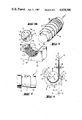
- FIG. 5 is a schematic view in perspective illustration of a first embodiment of a device for producing the slide bearing according to the invention
- FIG. 5A is a perspective detail of the portion VA of FIG. 5;
- FIG. 6 is a schematic view in perspective illustration of a second embodiment of a device for producing the slide bearing according to the invention.
- FIG. 6A is a perspective detail of the portion VIA of FIG. 6;
- FIG. 7 is a schematic view in perspective illustration of a third embodiment of a device for producing the slide bearing according to the invention.
- FIG. 7A is a perspective detail of the portion VIIA of FIG. 7;
- FIG. 8 is a schematic view of a fourth embodiment of a device for producing the slide bearing according to the invention.
- FIG. 9 is a diagram showing another calibration technique.
- FIGS. 1 and 2 show a plain or slide bearing prior and after being treated by a method according to the invention.
- the slide bearing includes a base or support shell of steel 11a on which a metallic bearing layer 11, e.g., based on copper or aluminum is applied by coating the layer 11 on the previously shaped support shell or coating it on a steel strip or steel plate which is then shaped to a semi-circular bearing bush 19 (see e.g. FIG. 5).
- the metallic layer 11 is provided with indentations 12 extending in a helical manner or constituted by concentric grooves.
- the indentations 12 are provided, e.g., by respectively boring the surface of the layer 11 and are parted from each other by intermediately extending support webs or elevations 13. As illustrated in FIG. 1, the indentations 12 have a depth t and are spaced from each other in radial direction by a distance v. The width of the elevations 13 in between adjacent circumferential indentations 12 is designated by s.
- the indentations 12 are provided in a helical manner. It is, however, certainly possible to provide the surface of the layer 11 with crossing indentations 12a, 12b so as to obtain substantially diamond-shaped areas or lands 12c by the thus intersecting grooves.
- a barrier layer or binding layer 14 over which a sliding layer 15 is applied which is made of metal and/or plastic material and in comparison to the metallic layer 11 is of softer consistency.
- the sliding layer 15 is applied onto the barrier layer 14 with a predetermined thickness, e.g., by electroplating, cathode sputtering, spraying or any other suitable coating process and can have a multi-layer structure. It should be noted, however, that the sliding layer 15 may certainly be applied directly onto the metallic layer 11.
- the sliding layer 15 when being applied onto the barrier layer 14 or on the metallic layer 11, the sliding layer 15 has a wave-like surface 16 of a predetermined thickness d 1 as it covers the grooves 12 as well as the elevations 13. In order to level the surface 16, the latter is subjected to a plastic shaping. Since the material of the sliding layer 15 is sufficiently soft, pressure applied onto the elevations 13 will cause the material to be displaced and to flow into the indentations 12. The pressure is maintained until the surface 16 of the sliding layer 15 is levelled and smooth as shown in FIG. 2.
- the elevations 13 which are made of hard material are permanently covered by a soft and adapting layer having a thickness d 2 of few micrometers while the layer above the grooved indentations 12 has a thickness d 3 .
- the relationship between the thicknesses of the sliding layer 15 prior and after the plastic shaping is thus as follows:
- FIGS. 3 and 4 show a raster electron microscopic image corresponding to FIGS. 1 and 2. Since FIGS. 3 and 4 are provided to particularly illustrate texture lines 17 of the sliding layer 15, FIG. 3 does not show the wave-like progression of the layer 15. Both images show the metallic layer 11 which is covered by the barrier of binding layer 14 and the sliding layer 15. Prior to the plastic shaping, the sliding layer 15 has homogeneous texture lines 17 which extend uniformly along the elevations 13 and the indentations 12.
- FIGS. 5 to 8 several embodiments are shown to provide the plastic shaping of the sliding layer 15 as previously described.
- a pressing device A including a die 18 which is provided with a semi-circular recess 18a in which the bearing bush 19 with a radius R 2 fits in an accurate manner.
- the bearing bush 19 is already covered with the metallic layer 11 having grooved indentations 12 and intermediate support elevations 13.
- a pressure ram 20 is pressed onto the bearing bush 19 by applying a force P 1 in direction of the indicated arrow until the surface 16 of the sliding layer 15 is levelled.
- the pressure ram 20 is of semi-circular shape and has such a radius R 1 so as to match precisely the facing contour of the bearing bush 19.
- the selection of the ratio between the radii R 1 and R 2 as well as the application of a sufficient pressing force P 1 is of importance.
- the pressing device A as three-way press in which the bearing bush 19 is subjected to pressure applied from various directions, preferably in directions normal to each other.
- the additional forces P 2 act on the lateral walls 18b of the die 18 (as indicated by the respective arrows) so as to be normal to the force P 1 .
- a uniform levelling of the surface 16 is secured as the forces P 2 will press the bearing bush 19 against the pressure ram 20.
- the wall thickness of the bearing bush 19 varies within certain tolerances, the levelling of the sliding surface 16 will not be affected thereby.
- the die 18 or the pressure ram 20 can be floatingly or resiliently suspended.
- the desired ratio of the layer thickness d 2 above the indentations 12 and of the layer thickness d 3 above the elevations 13 is dependent on the radius R 1 of the pressure ram 20 and the radius R 2 of the bearing bush 19 as well as on the pressure forces P 1 , P 2 and the thickness d 1 of the sliding layer 15 prior to the plastic shaping. Further parameters to be considered are the material properties as well as the profile of the indentations 12, i.e., the distance v between the elevations 13, the width s of the elevations and the depth t of the indentations 12. If necessary, the bearing bush 19 can be heated in order to support the levelling or smoothing of the surface 16. In some cases, it may be sufficient to provide the plastic shaping not along the entire width s above the support elevations 13 but only partially, e.g., along the apex.
- a rolling device B is shown for levelling the sliding surface 16 of the layer 15 and including a receptacle 22 provided with a semi-circular recess 22a. Fitted in an accurate manner within the recess 22a is the bearing bush 19 having the radius R 2 and against which a roller drum 23 is pressed by applying a force P 3 onto handle 23a.
- the drum 23 has a radius R 3 which is smaller than the radius R 2 .
- the receptacle 22 and the bearing bush 19 is caused by suitable means (not shown) to swing back and forth in direction of arrows 33 so that under force P 3 , softer layer material on the elevations 13 is forced into the indentations 12 and the surface 16 is uniformly levelled and smoothed.
- the rolling step can be executed in one or several gradual steps.
- the parameters as radius R 2 of the bearing bush 19, radius R 3 of the drum, force P 3 , layer thickness d 1 , d 2 , d 3 , distance v between the elevations 13 and depth t of the indentations depend on each other and thus must be correspondingly coordinated.
- FIG. 7 shows a calibrating device C including a receptacle 24 provided with a semi-circular recess 24a in which the bearing bush 19 with radius R 2 is accurately inserted
- the surface 16 is levelled by a calibrating instrument 25 which is moved in a similar manner as a broach over the concave arch of the sliding layer 15 of the bearing bush 19 so as to level the surface 16.
- the calibrating instrument 25 includes a plurality of successively arranged disks 26 of gradually increasing radii, i.e., radius R 4 of the foremost disk 29 is smaller than the next following radius R 5 which in turn is smaller than the radius of the next following disk 26 and so on (R 4 ⁇ R 5 ⁇ R n ).
- the radii of the disks 26 must be adjusted to each other in order to prevent a chip removal from the bearing bush 19 during calibrating of the surface 16.
- the surface contour of the calibrating instrument 25, i.e., of the disks 26 must be considered as well as the dimensions of the layer thicknesses d 1 , d 2 , d 3 , depth t and distance v of the indentations 12 and width s of the elevations 13 to preclude shearing and lamination of the material. Considering these factors, upon movement of the calibrating instrument 25, sliding material is moved from the support elevations 13 into the indentations 12 so as to provide a levelled surface 16 of the sliding layer 15.
- the calibrating instrument 25 is moved from both sides through the concave arch of the bearing bush 19.
- the calibrating instrument 25 can be provided with a conical head to which an essentially cylindrical calibrating body is connected. This embodiment is, however, not shown.
- FIG. 8 A further embodiment for providing a sliding bearing with levelled and smooth surface is illustrated in FIG. 8 which refers to the instance when band material is used as base for producing the bearing bush 19.
- a bending and rolling device D which includes opposing clamping jaws 28 retaining an elongated compound or sandwich band 27 which is then to be shaped into the bearing bush of the sliding bearing.
- the compound band 27 consists of a sheet steel which is coated with the metallic layer 11, e.g., by roller plating.
- the grooved or helical profile is not provided in the already finished bearing bush but is cut or plastically shaped into the semi-finished compound band consisting of steel and metallic layer 11.
- the barrier or binding layer 14 and finally the sliding layer 15 is applied to obtain the compound band 27 which is then shaped in the bending and rolling device D and has a structure and profile as illustrated in FIGS. 1 and 3 whereby the grooved indentations 12 and the elevations 13 extend parallel to each other or with a pitch to the longitudinal axis of the compound band 27.
- the bending and rolling device D further includes a roll arbor 29 which has one portion of semi-cylindrical shape so as to define a circumference 30 around which the compound band 27 is eventually bent and simultaneously rolled to provide the levelling of surface 16 of the sliding layer 15.
- the semi-cylindrical portion of the arbor 29 has a radius R a as measured from its respective center A.
- a press drum 32 Cooperating with the roll arbor 29 and arranged at a distance thereto is a press drum 32 which is rotatable about its center B and has a radius R b .
- the press drum 32 is connected to a not shown swivel arm which causes the drum 32 to move along a predetermined path--as indicated by dash-dot line 34--around the circumference 30 of the arbor 29.
- the connection of the swivel arm to the press drum 32 is such that the swivel axis of the swivel arm extends in the center A of the roll arbor 29.
- the distance of their respective centers A and B is slightly smaller than the total amount of the length of the radii R a and R b and the width d c of the compound band 27.
- the compound band 27 When being clamped between the jaws 28, the compound band 27 has a still elongated shape as indicated by dotted line 35.
- the press drum 32 is in its starting position which is indicated in dash-dotted line at the right hand side of the arbor 9. Thereafter, the swivel arm is actuated to rotate the drum 32 about the circumference 30 of the arbor 29 so that the compound band 27 is pressed against and bent around the arbor 29. Pressure is thus applied against the surface of the compound band 27 provided with the sliding layer 15 so that layer material above the elevations 13 is carried off and forced to flow into the indentations 12.
- the compound band 27 can be shaped to a bearing bush 19 and simultaneously provided with a levelled surface 16.
- the so-bent compound band is severed from the remaining portions thereof by opposing cutters 31 which are arranged at the arbor 29 at the end sections of the semi-cylindrical circumference 30 so that the bearing bush can eventually be provided.
- the coating material is forced into the goods and the bearing is calibrated by a calibrating tool 50 having a conical head 51 followed by a substantially cylindrical calibrating body 52.
Landscapes
- Engineering & Computer Science (AREA)
- General Engineering & Computer Science (AREA)
- Mechanical Engineering (AREA)
- Sliding-Contact Bearings (AREA)
Abstract
In a sliding bearing, a metallic layer is coated on a bearing base bush and is provided with grooved or helical or crossing indentations with intermediate elevations. Applied in a uniform manner onto the so-formed metallic layer is a sliding layer of softer material. Under pressure or application of shear forces, the material of the sliding layer provided above the elevations is forced through plastic shaping to flow into the indentations so as to provide a levelled and smooth sliding surface covering the metallic layer.
Description
Our present invention relates to a plain or sliding bearing with inhomogenous surface layer and more particularly, to a heavy-duty plain sliding bearing, and to an apparatus and a method of making same.
A plain or sliding bearing as opposed to a roller bearing has a surface in sliding friction contact with another surface of a moving member, e.g. a shaft to be journaled.
The bearing of British Pat. No. 524,128 has a surface composed of an anti-friction layer which is divided into a plurality of separate sections by thin ribs of metal which is harder than the material used for the anti-friction layer. The ribs extend essentially in circumferential direction of the sliding surface of the bearing and are arranged evenly throughout the bearing metal e.g. in a helical or screwthread pattern. Such bearings are thus also called grooved or helical sliding bearings.
These bearings have the disadvantage that the ridges of the ribs are exposed which means that the hard material (of aluminum or copper) of which these ribs are made is exposed. This considerably complicates the required adjustment of the bearing to the trunnion during the running-in phase. Moreover, the sliding and emergency running properties of the ribs are insufficient during disturbances caused, e.g., by oil deficiency or accumulation of dirt.
Consequently, it has been proposed to coat the ribs with a thin layer of softer lead alloy or tin alloy. In the case of sliding bearings for large engines, the German patent publication No. DE-OS 19 30 010 proposes to provide the metallic layer applied onto the bearing ridges with crossing indentations and to cover it with a layer of softer material by filling the indentations. Although the loading capacity of sliding bearings increases with decreasing thickness of the sliding surface, the support ribs can still be coated with a relatively thick layer between 0.01 to 0.05 mm thickness. This range can easily be maintained by reboring the sliding surface a second time after electroplating.
Highly loaded connecting rod bearings and main bearings of motor vehicles require in general a total thickness of the sliding surface of approximately 0.01 to 0.03 mm. To counter fatigue, this thickness range may also not be exceeded in sliding surfaces of grooved or helical sliding bearings for such engines. In view of the higher load a considerably lower thickness of the cover layer must be selected than would be the case in large motors. To guarantee this thickness range also during an industrial scale manufacture, it is necessary to limit the tolerances during the cutting of the sliding surface to such an extent that an economic production is unattainable. It has been proposed to apply the covering layer in an additional working cycle, e.g. by electroplating, cathodic sputtering or spraying. However, this is complicated and cumbersome and thus also not economical. Moreover, the provision of such an additional working cycle is not technically feasible in some types of bearing materials.
It is thus the principal object of our present invention to provide an improved sliding bearing which can be produced in a most efficient and economical manner with superior properties.
It is also an object of the invention to provide a highly loadable (heavy duty) plain bearing which manifests, even under extremely high loads, outstanding sliding, wear and corrosion-resistance characteristics during run-in and in emergency operations as well as during normal operations.
It is yet another object to provide an improved method of making such a bearing.
We realize these objects according to the invention by providing a sliding bearing in such a manner that the first layer which is provided with the indentations and intermediate elevations is covered by a second layer of softer material wherein material of the second layer is forced to flow from the elevations into the indentations to provide a levelled and smooth surface of the second layer over the first layer, i.e. the filling of the indentations is effected by the forced leveling.
By providing a levelled surface only through plastic shaping a highly loadable sliding bearing is obtained which combines the advantages of a multi-layer bearing with the advantages of a grooved or helical bearing as known in large engines. Apart from the extreme load carrying ability, the sliding bearing according to the invention has superior sliding properties, wear and corrosion resistance and is characterized by excellent running-in and emergency running properties.
Preferably, the material thickness of the second or upper sliding layer above the elevations should only be a few micrometers. As tests have shown, this thickness range provides the sliding bearing with improved adaptations properties and anti-seizing properties in comparison to conventional grooved or helical bearings. Moreover, the sliding bearing according to the invention has an increased resistance against erosion of the soft sliding layer within the indentations or grooves.
In the production of such a sliding bearing, the first layer is coated on the base element which can be a steel support shell or an elongated band and then provided with grooved or helical or crossing indentations. Thereafter, the second layer be applied on the first layer in a uniform manner and with a predetermined thickness so that the second layer extends in a wave-like manner over the indentations and elevations. Through the following plastic shaping according to the invention, the wave-like sliding surface is levelled without any additional cutting but solely under application of pressure and/or shear forces.
The levelling of the sliding surface according to the invention prevents the occurrance of abnormally high wear during the running-in phase as this was the case when producing grooved or helical bearings with sliding surfaces in the micrometer range by employing methods known so far. The elevations which consist of harder material are continuously covered by a thin layer of soft and adaptable material.
According to the teachings of the present invention, several apparatuses and methods are applicable to provide the plastic shaping of the second layer. In one technique, the base element is inserted into a press die and then, a pressure ram is pressed against the second or uppermost layer so as to force the softer material to flow from the elevations into the indentations. Preferably, a three-way press is used by which several forces are applied against the base element from different directions so that tolerances of the wall thickness of the press die can be neglected. Advantageously, the forces are directed perpendicular to each other.
As an alternative to the pressing method, the levelling of the sliding surface can be obtained through a rolling method in which the base element provided in a receptacle which swings back and forth is treated by a roller drum which rolls along the second layer under a predetermined pressure.
A further proposal utilizes a calibrating instrument which is moved over the second layer of the base element to level the latter in a non-cutting manner and under prevention of material laminations and material shearings. The calibrating instrument which works like a broach is moved through the usually arched vault of the base element and may consist of several successively arranged disks with gradually increasing radius. The gradation of the radii must be selected in such a manner that no chips are cut.
It is, however, also possible to provide the calibrating instrument with a conical head to which an essentially cylindrical cylinder body is connected.
When using band material as the starting material for the bearing bush to be produced, we can provide a bending and rolling method in which the elongated bond previously coated with the first layer including the indentations and elevations and then with the second layer is pressed by a roller drum against the semi-circular circumference of a roller arbor so that the band is shaped into the eventual form of the bearing bush and its second layer is simultaneously levelled.
According to this method, the grooved or helical profile is not cut into the already finished bearing bush but rather is provided by cutting or plastic shaping in the compound band which is of steel and has been previously coated with the first layer.
The above and other objects, features and advantages of our present invention will now be described in greater detail with reference to the accompanying drawing in which:
FIG. 1 is a cross sectional view on an enlarged scale of a slide bearing prior to being treated according to a method of the invention;
FIG. 1A is a perspective detail of a surface of the bearing alloy before coating;
FIG. 1B is a sectional detail of the portion 1B of FIG. 1;
FIG. 2 is a cross sectional view according to FIG. 1 illustrating the slide bearing after being treated according to the method of the invention;
FIG. 2A is a sectional detail of the portion IIA of FIG. 2;
FIG. 3 illustrates a scanning electron microscopic image of the slide bearing of FIG. 1;
FIG. 4 illustrates a scanning electron microscopic image of the slide bearing of FIG. 2;
FIG. 5 is a schematic view in perspective illustration of a first embodiment of a device for producing the slide bearing according to the invention;
FIG. 5A is a perspective detail of the portion VA of FIG. 5;
FIG. 6 is a schematic view in perspective illustration of a second embodiment of a device for producing the slide bearing according to the invention;
FIG. 6A is a perspective detail of the portion VIA of FIG. 6;
FIG. 7 is a schematic view in perspective illustration of a third embodiment of a device for producing the slide bearing according to the invention;
FIG. 7A is a perspective detail of the portion VIIA of FIG. 7;
FIG. 8 is a schematic view of a fourth embodiment of a device for producing the slide bearing according to the invention; and
FIG. 9 is a diagram showing another calibration technique.
FIGS. 1 and 2 show a plain or slide bearing prior and after being treated by a method according to the invention. The slide bearing includes a base or support shell of steel 11a on which a metallic bearing layer 11, e.g., based on copper or aluminum is applied by coating the layer 11 on the previously shaped support shell or coating it on a steel strip or steel plate which is then shaped to a semi-circular bearing bush 19 (see e.g. FIG. 5). Along the circumference of its running surface, the metallic layer 11 is provided with indentations 12 extending in a helical manner or constituted by concentric grooves. The indentations 12 are provided, e.g., by respectively boring the surface of the layer 11 and are parted from each other by intermediately extending support webs or elevations 13. As illustrated in FIG. 1, the indentations 12 have a depth t and are spaced from each other in radial direction by a distance v. The width of the elevations 13 in between adjacent circumferential indentations 12 is designated by s.
In the present embodiments, the indentations 12 are provided in a helical manner. It is, however, certainly possible to provide the surface of the layer 11 with crossing indentations 12a, 12b so as to obtain substantially diamond-shaped areas or lands 12c by the thus intersecting grooves.
Covering the grooved surface of the layer 11 is a barrier layer or binding layer 14 over which a sliding layer 15 is applied which is made of metal and/or plastic material and in comparison to the metallic layer 11 is of softer consistency.
By providing the barrier layer 14 between the metallic layer 11 and the sliding layer 15 a diffusion of alloy components between the layers in highly stressed slide bearings subjected to considerable temperatures is prevented and thus a damaging of the sliding layer 15 is avoided. The sliding layer 15 is applied onto the barrier layer 14 with a predetermined thickness, e.g., by electroplating, cathode sputtering, spraying or any other suitable coating process and can have a multi-layer structure. It should be noted, however, that the sliding layer 15 may certainly be applied directly onto the metallic layer 11.
As shown in FIG. 1 by a cross-sectional view, when being applied onto the barrier layer 14 or on the metallic layer 11, the sliding layer 15 has a wave-like surface 16 of a predetermined thickness d1 as it covers the grooves 12 as well as the elevations 13. In order to level the surface 16, the latter is subjected to a plastic shaping. Since the material of the sliding layer 15 is sufficiently soft, pressure applied onto the elevations 13 will cause the material to be displaced and to flow into the indentations 12. The pressure is maintained until the surface 16 of the sliding layer 15 is levelled and smooth as shown in FIG. 2. Thus, the elevations 13 which are made of hard material are permanently covered by a soft and adapting layer having a thickness d2 of few micrometers while the layer above the grooved indentations 12 has a thickness d3. The relationship between the thicknesses of the sliding layer 15 prior and after the plastic shaping is thus as follows:
d.sub.2 <d.sub.1 <d.sub.3.
Turning now to FIGS. 3 and 4 which show a raster electron microscopic image corresponding to FIGS. 1 and 2. Since FIGS. 3 and 4 are provided to particularly illustrate texture lines 17 of the sliding layer 15, FIG. 3 does not show the wave-like progression of the layer 15. Both images show the metallic layer 11 which is covered by the barrier of binding layer 14 and the sliding layer 15. Prior to the plastic shaping, the sliding layer 15 has homogeneous texture lines 17 which extend uniformly along the elevations 13 and the indentations 12. After applying pressure onto the material of the sliding layer covering the elevations 13 and thus forcing material (which is of softer consistency than the material constituting the elevations 13) to flow into the indentations 12, a cross-linkage of the texture lines 17 is obtained at the junction between elevations 13 and grooved indentations, as clearly shown in FIG. 4. Consequently, an additional reinforcement or hardening (toughening) along the edges of the indentations, i.e., at the junctions to the elevations 13 is obtained because of the cross-linked texture lines 17.
In FIGS. 5 to 8, several embodiments are shown to provide the plastic shaping of the sliding layer 15 as previously described. Referring firstly to FIG. 5 in which a pressing device A is shown including a die 18 which is provided with a semi-circular recess 18a in which the bearing bush 19 with a radius R2 fits in an accurate manner. The bearing bush 19 is already covered with the metallic layer 11 having grooved indentations 12 and intermediate support elevations 13. Once being inserted, a pressure ram 20 is pressed onto the bearing bush 19 by applying a force P1 in direction of the indicated arrow until the surface 16 of the sliding layer 15 is levelled. The pressure ram 20 is of semi-circular shape and has such a radius R1 so as to match precisely the facing contour of the bearing bush 19. For achieving the requested levelling of the surface 16 along the entire circumference of the sliding layer 15, the selection of the ratio between the radii R1 and R2 as well as the application of a sufficient pressing force P1 is of importance.
Especially advantageous is the use of the pressing device A as three-way press in which the bearing bush 19 is subjected to pressure applied from various directions, preferably in directions normal to each other. In the embodiment of FIG. 5, the additional forces P2 act on the lateral walls 18b of the die 18 (as indicated by the respective arrows) so as to be normal to the force P1. Through the application of these three forces, a uniform levelling of the surface 16 is secured as the forces P2 will press the bearing bush 19 against the pressure ram 20. Thus, although the wall thickness of the bearing bush 19 varies within certain tolerances, the levelling of the sliding surface 16 will not be affected thereby.
In order to allow the forces to act in an even more uniform manner, the die 18 or the pressure ram 20 can be floatingly or resiliently suspended.
The desired ratio of the layer thickness d2 above the indentations 12 and of the layer thickness d3 above the elevations 13 is dependent on the radius R1 of the pressure ram 20 and the radius R2 of the bearing bush 19 as well as on the pressure forces P1, P2 and the thickness d1 of the sliding layer 15 prior to the plastic shaping. Further parameters to be considered are the material properties as well as the profile of the indentations 12, i.e., the distance v between the elevations 13, the width s of the elevations and the depth t of the indentations 12. If necessary, the bearing bush 19 can be heated in order to support the levelling or smoothing of the surface 16. In some cases, it may be sufficient to provide the plastic shaping not along the entire width s above the support elevations 13 but only partially, e.g., along the apex.
In FIG. 6, a rolling device B is shown for levelling the sliding surface 16 of the layer 15 and including a receptacle 22 provided with a semi-circular recess 22a. Fitted in an accurate manner within the recess 22a is the bearing bush 19 having the radius R2 and against which a roller drum 23 is pressed by applying a force P3 onto handle 23a. The drum 23 has a radius R3 which is smaller than the radius R2. In order to provide the rolling motion of the drum 23 along the circumference of the bearing bush 19, the receptacle 22 and the bearing bush 19 is caused by suitable means (not shown) to swing back and forth in direction of arrows 33 so that under force P3, softer layer material on the elevations 13 is forced into the indentations 12 and the surface 16 is uniformly levelled and smoothed.
The rolling step can be executed in one or several gradual steps. For obtaining optimum results upon levelling the surface 16, the parameters as radius R2 of the bearing bush 19, radius R3 of the drum, force P3, layer thickness d1, d2, d3, distance v between the elevations 13 and depth t of the indentations depend on each other and thus must be correspondingly coordinated.
Turning now to FIG. 7, which shows a calibrating device C including a receptacle 24 provided with a semi-circular recess 24a in which the bearing bush 19 with radius R2 is accurately inserted The surface 16 is levelled by a calibrating instrument 25 which is moved in a similar manner as a broach over the concave arch of the sliding layer 15 of the bearing bush 19 so as to level the surface 16. In the embodiment of FIG. 7, the calibrating instrument 25 includes a plurality of successively arranged disks 26 of gradually increasing radii, i.e., radius R4 of the foremost disk 29 is smaller than the next following radius R5 which in turn is smaller than the radius of the next following disk 26 and so on (R4 <R5 <Rn). The radii of the disks 26 must be adjusted to each other in order to prevent a chip removal from the bearing bush 19 during calibrating of the surface 16.
In addition to the dependency of the radii of the disks 26 on each other, the surface contour of the calibrating instrument 25, i.e., of the disks 26 must be considered as well as the dimensions of the layer thicknesses d1, d2, d3, depth t and distance v of the indentations 12 and width s of the elevations 13 to preclude shearing and lamination of the material. Considering these factors, upon movement of the calibrating instrument 25, sliding material is moved from the support elevations 13 into the indentations 12 so as to provide a levelled surface 16 of the sliding layer 15.
For achieving a levelled surface 16 of the sliding layer 15 of high strength, the calibrating instrument 25 is moved from both sides through the concave arch of the bearing bush 19.
Apart from the design of the calibrating instrument 25 as described in FIG. 7, it may be noted that any other suitable design is possible. For instance, the calibrating instrument can be provided with a conical head to which an essentially cylindrical calibrating body is connected. This embodiment is, however, not shown.
A further embodiment for providing a sliding bearing with levelled and smooth surface is illustrated in FIG. 8 which refers to the instance when band material is used as base for producing the bearing bush 19. Accordingly, a bending and rolling device D is shown which includes opposing clamping jaws 28 retaining an elongated compound or sandwich band 27 which is then to be shaped into the bearing bush of the sliding bearing. The compound band 27 consists of a sheet steel which is coated with the metallic layer 11, e.g., by roller plating. In contrast to the previously described embodiments, the grooved or helical profile is not provided in the already finished bearing bush but is cut or plastically shaped into the semi-finished compound band consisting of steel and metallic layer 11. Thereafter, the barrier or binding layer 14 and finally the sliding layer 15 is applied to obtain the compound band 27 which is then shaped in the bending and rolling device D and has a structure and profile as illustrated in FIGS. 1 and 3 whereby the grooved indentations 12 and the elevations 13 extend parallel to each other or with a pitch to the longitudinal axis of the compound band 27.
As can be seen from FIG. 8, the bending and rolling device D further includes a roll arbor 29 which has one portion of semi-cylindrical shape so as to define a circumference 30 around which the compound band 27 is eventually bent and simultaneously rolled to provide the levelling of surface 16 of the sliding layer 15. The semi-cylindrical portion of the arbor 29 has a radius Ra as measured from its respective center A.
Cooperating with the roll arbor 29 and arranged at a distance thereto is a press drum 32 which is rotatable about its center B and has a radius Rb. The press drum 32 is connected to a not shown swivel arm which causes the drum 32 to move along a predetermined path--as indicated by dash-dot line 34--around the circumference 30 of the arbor 29. The connection of the swivel arm to the press drum 32 is such that the swivel axis of the swivel arm extends in the center A of the roll arbor 29.
In order to provide a correct relationship between the roll arbor 29 and the press drum 32, the distance of their respective centers A and B is slightly smaller than the total amount of the length of the radii Ra and Rb and the width dc of the compound band 27.
When being clamped between the jaws 28, the compound band 27 has a still elongated shape as indicated by dotted line 35. The press drum 32 is in its starting position which is indicated in dash-dotted line at the right hand side of the arbor 9. Thereafter, the swivel arm is actuated to rotate the drum 32 about the circumference 30 of the arbor 29 so that the compound band 27 is pressed against and bent around the arbor 29. Pressure is thus applied against the surface of the compound band 27 provided with the sliding layer 15 so that layer material above the elevations 13 is carried off and forced to flow into the indentations 12. Through proper selection of the pressure by which the compound band 27 is pressed against the arbor 29 through the press drum 32 and by properly coordinating the interrelated parameters as radii Ra and Rb, thickness d1 of the sliding layer 15, the compound band 27 can be shaped to a bearing bush 19 and simultaneously provided with a levelled surface 16. The so-bent compound band is severed from the remaining portions thereof by opposing cutters 31 which are arranged at the arbor 29 at the end sections of the semi-cylindrical circumference 30 so that the bearing bush can eventually be provided.
We should note, however, that there are instances in which an exact coordination of the individual parameters is not feasible so that the described bending and rolling process will not result in the desired surface quality of the bearing bush 19; in these instances, the levelling and smoothing of the sliding surface 15 through rolling should be provided prior to the actually bending step.
It is, however, also possible to provide a two-step operation to level the surface 16 and to form the compound band 27 to the bearing bush. In a first step, rolling of the surface 16 is provided while during the second step, the compound band 27 is bent and simultaneously the rolling action and thus further levelling of the sliding layer 15 takes place. In both steps, the applied pressures during rolling and bending are coordinated such that portions of the softer material covering the elevations 13 flows into the indentations 12 so as to provide a sliding bearing with smooth and levelled surface and in any case the support elevations 13 are covered by a thin sliding layer 15 of a thickness of few micrometers.
In FIG. 9, the coating material is forced into the goods and the bearing is calibrated by a calibrating tool 50 having a conical head 51 followed by a substantially cylindrical calibrating body 52.
Claims (7)
1. Apparatus for producing a sliding bearing, comprising:
first coating means for covering a bearing base element with a first layer having a surface;
forming means for providing said surface with indentations and intermediate elevations;
second coating means for applying a second layer of predetermined thickness onto said first layer wherein said second layer is of softer material than the material of said first layer; and
treating means for forming portions of said second layer covering the elevations through plastic shaping to flow into the indentations so as to obtain a levelled and smooth surface and to provide said second layer of requested thickness above the elevations.
2. An apparatus as defined in claim 1 wherein said treating means includes a press die in which said base element provided with said first and second layers is inserted, and a pressure ram having a contour adapted to the contour of said facing base element, said pressure ram being movable in direction towards said base element so as to force material from said elevations to flow into said indentations.
3. An apparatus as defined in claim 1 wherein said treating means includes a receptacle in which said base element provided with said first and second layers is inserted, and a roller drum rolling on said base element along said second layer so as to force material from said elevations to flow into said indentations.
4. An apparatus as defined in claim 1 wherein said treating means includes a receptacle in which said base element provided with said first and second layers is inserted, and a calibrating instrument movable over said base element so as to force material from said elevations to flow into said indentations.
5. Apparatus as defined in claim 4 wherein said calibrating instrument includes a conical head and an essentially cylindrical calibrating body connected to said head.
6. An apparatus as defined in claim 4 wherein said calibrating instrument includes a plurality of successively arranged calibrating disks with gradually increasing radius.
7. Ap apparatus as defined in claim 1 wherein said treating means includes clamping jaws to retain said base element provided with said first and second layers and being in a band-like elongated form, a roll arbor having a circumferential section defining the shape of said base element, a roller drum arranged at a distance to said roll arbor so that said elongated base element extends therebetween, said roller drum being movable around said roll arbor so as to bend said base element and level said second layer by pressing said base element against said circumferential section of said roll arbor, and cutters connected to said roll arbor to sever said bend base element.
Applications Claiming Priority (2)
| Application Number | Priority Date | Filing Date | Title |
|---|---|---|---|
| DE3415929 | 1984-04-28 | ||
| DE3415929A DE3415929A1 (en) | 1984-04-28 | 1984-04-28 | HIGH-DENSITY SLIDING BEARING WITH INHOMOGENIC SLIDING LAYER |
Publications (1)
| Publication Number | Publication Date |
|---|---|
| US4658500A true US4658500A (en) | 1987-04-21 |
Family
ID=6234624
Family Applications (1)
| Application Number | Title | Priority Date | Filing Date |
|---|---|---|---|
| US06/728,076 Expired - Fee Related US4658500A (en) | 1984-04-28 | 1985-04-29 | Apparatus for fabricating a plain (sliding) bearing |
Country Status (4)
| Country | Link |
|---|---|
| US (1) | US4658500A (en) |
| BR (1) | BR8501991A (en) |
| DE (1) | DE3415929A1 (en) |
| GB (1) | GB2158164A (en) |
Cited By (14)
| Publication number | Priority date | Publication date | Assignee | Title |
|---|---|---|---|---|
| US4738010A (en) * | 1986-02-22 | 1988-04-19 | Kernforschungszentrum Karlsruhe Gmbh | Method of producing a sheet or plate-shaped structure as the bearing material for slide bearings |
| US4916929A (en) * | 1987-02-17 | 1990-04-17 | Otto Bihler | Method and apparatus for the production of part-circular arc elements |
| US4930910A (en) * | 1987-12-26 | 1990-06-05 | Honda Giken Kogyo Kabushiki Kaisha | Bearing arrangement |
| US4969251A (en) * | 1988-04-04 | 1990-11-13 | Pittsburgh Coil Technology | Method of making brake shoe stock (II) |
| US5153991A (en) * | 1989-10-19 | 1992-10-13 | The Glacier Metal Company Limited | Bearings |
| EP1085222A2 (en) * | 1999-09-14 | 2001-03-21 | Daido Metal Company Ltd. | Plain bearing and producing method thereof |
| EP1092885A2 (en) * | 1999-09-29 | 2001-04-18 | Daido Metal Company Ltd. | Plain bearing |
| US20030121152A1 (en) * | 2001-12-04 | 2003-07-03 | Johnson David L. | Methods for recreating fuel pump bearings |
| US20080292235A1 (en) * | 2007-05-25 | 2008-11-27 | Kabushiki Kaisha Toshiba | Sliding material, method of manufacturing same and bearing assembly |
| US20090080821A1 (en) * | 2007-09-25 | 2009-03-26 | Daido Metal Company Ltd 13F, Nagoya Hirokoji Bldg | Plain bearing |
| US20090078080A1 (en) * | 2005-12-21 | 2009-03-26 | Peter Kemnitz | Connecting Rod for an Internal Combustion Engine and Method for Its Production |
| US20180056623A1 (en) * | 2016-08-24 | 2018-03-01 | Hyundai Motor Company | Method for coating surface of moving part of vehicle and moving part of vehicle manufactured by the same |
| US9926968B2 (en) * | 2013-08-21 | 2018-03-27 | Mag Ias Gmbh | Sliding surface |
| WO2020237276A1 (en) * | 2019-05-29 | 2020-12-03 | Miba Gleitlager Austria Gmbh | Multilayer slide bearing and method for producing a multilayer slide bearing |
Families Citing this family (6)
| Publication number | Priority date | Publication date | Assignee | Title |
|---|---|---|---|---|
| DE4138420C2 (en) * | 1991-09-05 | 2001-03-08 | Faure Bertrand Sitztech Gmbh | Adjustment fitting for motor vehicle seats |
| BR9204743A (en) * | 1992-12-29 | 1994-11-29 | Metal Leve Sa | Multilayer bearing. |
| AT403194B (en) * | 1995-07-12 | 1997-11-25 | Miba Gleitlager Ag | METHOD FOR PRODUCING A SLIDING BEARING |
| DE102007058744B4 (en) * | 2007-12-05 | 2019-06-06 | Federal-Mogul Wiesbaden Gmbh | Slide bearing shell and bearing arrangement |
| DE102012222091B4 (en) * | 2012-12-03 | 2015-07-09 | Federal-Mogul Wiesbaden Gmbh | Method for producing a sliding bearing shell |
| DE102016220918A1 (en) * | 2016-10-25 | 2018-01-04 | Schaeffler Technologies AG & Co. KG | Well gear and a vehicle with the wave gear |
Citations (24)
| Publication number | Priority date | Publication date | Assignee | Title |
|---|---|---|---|---|
| GB123691A (en) * | 1918-08-15 | 1919-03-06 | Arthur Thomas Allen | A Bullet-proof Guard or Shield for Aeroplanes and like Machines. |
| US1331961A (en) * | 1918-08-27 | 1920-02-24 | Pressed Bearing Company Inc | Lined bearing |
| US1581394A (en) * | 1918-01-11 | 1926-04-20 | Dann Products Company | Composite element and method of making the same |
| FR674877A (en) * | 1929-05-10 | 1930-02-03 | Cleveland Graphite Bronze Co | Process for bonding dissimilar metals |
| US1753435A (en) * | 1928-01-09 | 1930-04-08 | Cleveland Graphite Bronze Co | Method of making lined bearings |
| DE523734C (en) * | 1930-05-06 | 1931-04-27 | Alfred Edouard Ricard | Process for the treatment of friction surfaces |
| US1819272A (en) * | 1927-09-22 | 1931-08-18 | Moraine Products Company | Bearing |
| US1892178A (en) * | 1930-12-15 | 1932-12-27 | Cleveland Graphite Bronze Co | Method of making bearing sleeves |
| GB395890A (en) * | 1932-03-03 | 1933-07-27 | Sperry Gyroscope Co Inc | Improvements in the manufacture of bearings for rotary shafts |
| US1950094A (en) * | 1927-12-09 | 1934-03-06 | Cleveland Graphite Bronze Co | Method of producing bearings |
| US1958089A (en) * | 1931-03-07 | 1934-05-08 | Johnson Bronze Co | Bearing element |
| DE608800C (en) * | 1933-07-30 | 1935-02-01 | Fried Krupp Grusonwerk Akt Ges | Device for the fractional condensation of metal vapors |
| US2031982A (en) * | 1931-09-28 | 1936-02-25 | Cleveland Graphite Bronze Co | Method of making bearings |
| GB468219A (en) * | 1935-12-31 | 1937-06-30 | George Bell | Improvements in bearings |
| GB524128A (en) * | 1938-12-28 | 1940-07-30 | Ettore Bugatti | Improvements in and relating to bearings |
| US2242439A (en) * | 1938-08-15 | 1941-05-20 | Nat Lead Co | Method of making journal bearings |
| US2534408A (en) * | 1947-10-17 | 1950-12-19 | Jr Harry M Bramberry | Relieved and filled cylinder surface |
| GB655914A (en) * | 1948-10-12 | 1951-08-08 | Marcel Louis Debrock | Process and device for interlocking two metallic parts connected together by casting |
| DE825779C (en) * | 1947-11-26 | 1951-12-20 | Gen Motors Corp | Metallic composite body, in particular composite bearing and method for its production |
| US2648580A (en) * | 1947-11-26 | 1953-08-11 | Gen Motors Corp | Aluminum base bearing |
| GB718073A (en) * | 1952-05-30 | 1954-11-10 | Glacier Co Ltd | Improvements in or relating to plain bearings |
| DE1260934B (en) * | 1964-02-29 | 1968-02-08 | Schmidt Gmbh Karl | Method and device for the production of clad strips for slide bearings |
| DE1938010A1 (en) * | 1969-07-26 | 1971-02-18 | Glyco Metall Werke | Plain bearing with inhomogeneous running layer and process for its manufacture |
| US4351175A (en) * | 1979-09-22 | 1982-09-28 | Taiho Kogyo Kabushiki Kaisha | Method of manufacturing an arc-like formed product and equipment for carrying out the method |
Family Cites Families (1)
| Publication number | Priority date | Publication date | Assignee | Title |
|---|---|---|---|---|
| GB1239691A (en) * | 1968-10-10 | 1971-07-21 |
-
1984
- 1984-04-28 DE DE3415929A patent/DE3415929A1/en not_active Ceased
-
1985
- 1985-04-26 BR BR8501991A patent/BR8501991A/en not_active IP Right Cessation
- 1985-04-26 GB GB08510682A patent/GB2158164A/en not_active Withdrawn
- 1985-04-29 US US06/728,076 patent/US4658500A/en not_active Expired - Fee Related
Patent Citations (24)
| Publication number | Priority date | Publication date | Assignee | Title |
|---|---|---|---|---|
| US1581394A (en) * | 1918-01-11 | 1926-04-20 | Dann Products Company | Composite element and method of making the same |
| GB123691A (en) * | 1918-08-15 | 1919-03-06 | Arthur Thomas Allen | A Bullet-proof Guard or Shield for Aeroplanes and like Machines. |
| US1331961A (en) * | 1918-08-27 | 1920-02-24 | Pressed Bearing Company Inc | Lined bearing |
| US1819272A (en) * | 1927-09-22 | 1931-08-18 | Moraine Products Company | Bearing |
| US1950094A (en) * | 1927-12-09 | 1934-03-06 | Cleveland Graphite Bronze Co | Method of producing bearings |
| US1753435A (en) * | 1928-01-09 | 1930-04-08 | Cleveland Graphite Bronze Co | Method of making lined bearings |
| FR674877A (en) * | 1929-05-10 | 1930-02-03 | Cleveland Graphite Bronze Co | Process for bonding dissimilar metals |
| DE523734C (en) * | 1930-05-06 | 1931-04-27 | Alfred Edouard Ricard | Process for the treatment of friction surfaces |
| US1892178A (en) * | 1930-12-15 | 1932-12-27 | Cleveland Graphite Bronze Co | Method of making bearing sleeves |
| US1958089A (en) * | 1931-03-07 | 1934-05-08 | Johnson Bronze Co | Bearing element |
| US2031982A (en) * | 1931-09-28 | 1936-02-25 | Cleveland Graphite Bronze Co | Method of making bearings |
| GB395890A (en) * | 1932-03-03 | 1933-07-27 | Sperry Gyroscope Co Inc | Improvements in the manufacture of bearings for rotary shafts |
| DE608800C (en) * | 1933-07-30 | 1935-02-01 | Fried Krupp Grusonwerk Akt Ges | Device for the fractional condensation of metal vapors |
| GB468219A (en) * | 1935-12-31 | 1937-06-30 | George Bell | Improvements in bearings |
| US2242439A (en) * | 1938-08-15 | 1941-05-20 | Nat Lead Co | Method of making journal bearings |
| GB524128A (en) * | 1938-12-28 | 1940-07-30 | Ettore Bugatti | Improvements in and relating to bearings |
| US2534408A (en) * | 1947-10-17 | 1950-12-19 | Jr Harry M Bramberry | Relieved and filled cylinder surface |
| US2648580A (en) * | 1947-11-26 | 1953-08-11 | Gen Motors Corp | Aluminum base bearing |
| DE825779C (en) * | 1947-11-26 | 1951-12-20 | Gen Motors Corp | Metallic composite body, in particular composite bearing and method for its production |
| GB655914A (en) * | 1948-10-12 | 1951-08-08 | Marcel Louis Debrock | Process and device for interlocking two metallic parts connected together by casting |
| GB718073A (en) * | 1952-05-30 | 1954-11-10 | Glacier Co Ltd | Improvements in or relating to plain bearings |
| DE1260934B (en) * | 1964-02-29 | 1968-02-08 | Schmidt Gmbh Karl | Method and device for the production of clad strips for slide bearings |
| DE1938010A1 (en) * | 1969-07-26 | 1971-02-18 | Glyco Metall Werke | Plain bearing with inhomogeneous running layer and process for its manufacture |
| US4351175A (en) * | 1979-09-22 | 1982-09-28 | Taiho Kogyo Kabushiki Kaisha | Method of manufacturing an arc-like formed product and equipment for carrying out the method |
Non-Patent Citations (2)
| Title |
|---|
| DE AN D 10918 of Jul. 24, 1952, (Application submitted to Deutsche Patentamt by Daimler Benz). * |
| DE-AN D 10918 of Jul. 24, 1952, (Application submitted to Deutsche Patentamt by Daimler Benz). |
Cited By (25)
| Publication number | Priority date | Publication date | Assignee | Title |
|---|---|---|---|---|
| US4738010A (en) * | 1986-02-22 | 1988-04-19 | Kernforschungszentrum Karlsruhe Gmbh | Method of producing a sheet or plate-shaped structure as the bearing material for slide bearings |
| US4916929A (en) * | 1987-02-17 | 1990-04-17 | Otto Bihler | Method and apparatus for the production of part-circular arc elements |
| US4930910A (en) * | 1987-12-26 | 1990-06-05 | Honda Giken Kogyo Kabushiki Kaisha | Bearing arrangement |
| US4969251A (en) * | 1988-04-04 | 1990-11-13 | Pittsburgh Coil Technology | Method of making brake shoe stock (II) |
| US5153991A (en) * | 1989-10-19 | 1992-10-13 | The Glacier Metal Company Limited | Bearings |
| US6491437B1 (en) | 1999-09-14 | 2002-12-10 | Daido Metal Company Ltd. | Plain bearing and producing method thereof |
| EP1085222A2 (en) * | 1999-09-14 | 2001-03-21 | Daido Metal Company Ltd. | Plain bearing and producing method thereof |
| EP1085222A3 (en) * | 1999-09-14 | 2002-09-25 | Daido Metal Company Ltd. | Plain bearing and producing method thereof |
| EP1092885A2 (en) * | 1999-09-29 | 2001-04-18 | Daido Metal Company Ltd. | Plain bearing |
| EP1092885A3 (en) * | 1999-09-29 | 2004-02-18 | Daido Metal Company Ltd. | Plain bearing |
| US20030121152A1 (en) * | 2001-12-04 | 2003-07-03 | Johnson David L. | Methods for recreating fuel pump bearings |
| US9726223B2 (en) | 2005-12-21 | 2017-08-08 | Mahle International Gmbh | Method for the production of a connecting rod for an internal combustion engine |
| US20090078080A1 (en) * | 2005-12-21 | 2009-03-26 | Peter Kemnitz | Connecting Rod for an Internal Combustion Engine and Method for Its Production |
| US20080292235A1 (en) * | 2007-05-25 | 2008-11-27 | Kabushiki Kaisha Toshiba | Sliding material, method of manufacturing same and bearing assembly |
| US8231276B2 (en) * | 2007-05-25 | 2012-07-31 | Kabushiki Kaisha Toshiba | Sliding material, method of manufacturing same and bearing assembly |
| US20090080821A1 (en) * | 2007-09-25 | 2009-03-26 | Daido Metal Company Ltd 13F, Nagoya Hirokoji Bldg | Plain bearing |
| US9926968B2 (en) * | 2013-08-21 | 2018-03-27 | Mag Ias Gmbh | Sliding surface |
| US20180056623A1 (en) * | 2016-08-24 | 2018-03-01 | Hyundai Motor Company | Method for coating surface of moving part of vehicle and moving part of vehicle manufactured by the same |
| CN107779815A (en) * | 2016-08-24 | 2018-03-09 | 现代自动车株式会社 | Method for the surface of coated vehicle running gear and the vehicle operation part by this method manufacture |
| US10737462B2 (en) * | 2016-08-24 | 2020-08-11 | Hyundai Motor Company | Method for coating surface of moving part of vehicle and moving part of vehicle manufactured by the same |
| CN107779815B (en) * | 2016-08-24 | 2021-04-02 | 现代自动车株式会社 | Method for coating the surface of a vehicle running part and vehicle running part produced by the method |
| WO2020237276A1 (en) * | 2019-05-29 | 2020-12-03 | Miba Gleitlager Austria Gmbh | Multilayer slide bearing and method for producing a multilayer slide bearing |
| CN113874634A (en) * | 2019-05-29 | 2021-12-31 | 米巴滑动轴承奥地利有限公司 | Multilayer sliding bearing and method for producing a multilayer sliding bearing |
| EP4324574A1 (en) * | 2019-05-29 | 2024-02-21 | Miba Gleitlager Austria GmbH | Multi-layer plain bearing and method for producing a multi-layer plain bearing |
| US12135061B2 (en) | 2019-05-29 | 2024-11-05 | Miba Gleitlager Austria Gmbh | Multilayer slide bearing and method for producing a multilayer slide bearing |
Also Published As
| Publication number | Publication date |
|---|---|
| DE3415929A1 (en) | 1985-10-31 |
| GB8510682D0 (en) | 1985-06-05 |
| BR8501991A (en) | 1985-12-31 |
| GB2158164A (en) | 1985-11-06 |
Similar Documents
| Publication | Publication Date | Title |
|---|---|---|
| US4658500A (en) | Apparatus for fabricating a plain (sliding) bearing | |
| EP3416760B1 (en) | Planishing roll, method for planishing a flat product therewith and flat product therefrom | |
| US4881355A (en) | Cold roll-formed structures and method and apparatus for producing same | |
| US4770018A (en) | Method for producing cold roll-formed structures | |
| Schey et al. | Shape changes in the upsetting of slender cylinders | |
| US4048703A (en) | Collar sleeves and process and tool for the manufacture thereof | |
| US2648580A (en) | Aluminum base bearing | |
| US6688768B2 (en) | Bearing assembly and manufacturing method | |
| GB2054648A (en) | To extremely high surface pressure/friction/temperature producing workpieces with adaptation layer for subjection | |
| US2971248A (en) | Composite bearings and method of forming the same | |
| CA1245837A (en) | Production procedure of brake shoes | |
| JPH0811966B2 (en) | High loaded sliding bearing | |
| WO2008011860A1 (en) | Bearing shell, and bearing for connecting rods | |
| WO1994015108A1 (en) | Multilayer sliding bearing | |
| US3248776A (en) | Method of making a self-aligning rod end bearing | |
| WO2008077735A1 (en) | Gear shift fork device | |
| JPH11293304A (en) | Double-layered sintered sliding member and its production | |
| US4138775A (en) | Method for manufacturing a shoe for a swash-plate type compressor | |
| CA1076783A (en) | Procedure in the manufacturing of a covering for a paper machine roll by winding from profiled strip | |
| US5195244A (en) | Bearings | |
| US4207762A (en) | Method of forming high quality forgings | |
| EP0486320B1 (en) | Method of manufacturing a side rail of combined oil ring | |
| US1646371A (en) | Bearing and method of making same | |
| DE2413426C2 (en) | Flexible metal seal | |
| JP2007522410A (en) | Sliding bearing element and manufacturing method |
Legal Events
| Date | Code | Title | Description |
|---|---|---|---|
| AS | Assignment |
Owner name: GLYCO-METALL-WRKE DAELEN & LOOS GMBH STIELSTRASSE Free format text: ASSIGNMENT OF ASSIGNORS INTEREST.;ASSIGNORS:ENGEL, ULRICH;NIEGEL, FRITZ;CROSCHEN, JURGEN;REEL/FRAME:004426/0143 Effective date: 19850611 |
|
| REMI | Maintenance fee reminder mailed | ||
| LAPS | Lapse for failure to pay maintenance fees | ||
| STCH | Information on status: patent discontinuation |
Free format text: PATENT EXPIRED DUE TO NONPAYMENT OF MAINTENANCE FEES UNDER 37 CFR 1.362 |
|
| FP | Lapsed due to failure to pay maintenance fee |
Effective date: 19910421 |
|
| LAPS | Lapse for failure to pay maintenance fees |
Free format text: PATENT EXPIRED FOR FAILURE TO PAY MAINTENANCE FEES (ORIGINAL EVENT CODE: EXP.); ENTITY STATUS OF PATENT OWNER: LARGE ENTITY |