US4633209A - DC electromagnet, in particular for an electric switching apparatus - Google Patents
DC electromagnet, in particular for an electric switching apparatus Download PDFInfo
- Publication number
- US4633209A US4633209A US06/756,622 US75662285A US4633209A US 4633209 A US4633209 A US 4633209A US 75662285 A US75662285 A US 75662285A US 4633209 A US4633209 A US 4633209A
- Authority
- US
- United States
- Prior art keywords
- air gap
- plunger
- coil
- electromagnet
- tube
- Prior art date
- Legal status (The legal status is an assumption and is not a legal conclusion. Google has not performed a legal analysis and makes no representation as to the accuracy of the status listed.)
- Expired - Fee Related
Links
- 230000006698 induction Effects 0.000 claims description 14
- 230000004907 flux Effects 0.000 claims description 13
- 230000002093 peripheral effect Effects 0.000 claims description 8
- 239000000463 material Substances 0.000 claims description 5
- 230000001154 acute effect Effects 0.000 claims 1
- 230000008901 benefit Effects 0.000 description 6
- 230000009467 reduction Effects 0.000 description 6
- 238000004364 calculation method Methods 0.000 description 5
- 230000000694 effects Effects 0.000 description 4
- 230000007423 decrease Effects 0.000 description 3
- 238000009826 distribution Methods 0.000 description 3
- 230000003321 amplification Effects 0.000 description 2
- 239000003831 antifriction material Substances 0.000 description 2
- 230000005540 biological transmission Effects 0.000 description 2
- 230000006835 compression Effects 0.000 description 2
- 238000007906 compression Methods 0.000 description 2
- 230000002349 favourable effect Effects 0.000 description 2
- 238000009413 insulation Methods 0.000 description 2
- 238000004519 manufacturing process Methods 0.000 description 2
- 238000000034 method Methods 0.000 description 2
- 238000003199 nucleic acid amplification method Methods 0.000 description 2
- 230000011664 signaling Effects 0.000 description 2
- 230000009471 action Effects 0.000 description 1
- 230000004323 axial length Effects 0.000 description 1
- 238000010276 construction Methods 0.000 description 1
- 238000010586 diagram Methods 0.000 description 1
- 230000006872 improvement Effects 0.000 description 1
- 238000002955 isolation Methods 0.000 description 1
- 238000011031 large-scale manufacturing process Methods 0.000 description 1
- 230000007246 mechanism Effects 0.000 description 1
- 230000004048 modification Effects 0.000 description 1
- 238000012986 modification Methods 0.000 description 1
- 238000005457 optimization Methods 0.000 description 1
- 230000035515 penetration Effects 0.000 description 1
- 230000008569 process Effects 0.000 description 1
- 230000000750 progressive effect Effects 0.000 description 1
- 229920006395 saturated elastomer Polymers 0.000 description 1
- 230000035939 shock Effects 0.000 description 1
- 238000004088 simulation Methods 0.000 description 1
- 239000007787 solid Substances 0.000 description 1
Images


Classifications
-
- H—ELECTRICITY
- H01—ELECTRIC ELEMENTS
- H01F—MAGNETS; INDUCTANCES; TRANSFORMERS; SELECTION OF MATERIALS FOR THEIR MAGNETIC PROPERTIES
- H01F7/00—Magnets
- H01F7/06—Electromagnets; Actuators including electromagnets
- H01F7/08—Electromagnets; Actuators including electromagnets with armatures
- H01F7/16—Rectilinearly-movable armatures
- H01F7/1607—Armatures entering the winding
-
- H—ELECTRICITY
- H01—ELECTRIC ELEMENTS
- H01F—MAGNETS; INDUCTANCES; TRANSFORMERS; SELECTION OF MATERIALS FOR THEIR MAGNETIC PROPERTIES
- H01F7/00—Magnets
- H01F7/06—Electromagnets; Actuators including electromagnets
- H01F7/08—Electromagnets; Actuators including electromagnets with armatures
- H01F7/16—Rectilinearly-movable armatures
- H01F7/1638—Armatures not entering the winding
Definitions
- the invention relates to a DC electromagnet, in particular for an electric switching apparatus, comprising a magnetizable yoke in the form of a pot having:
- a mobile armature subjected to the action of a return spring and whose peripheral pole surfaces, having a form which increases their values, cooperate with surfaces having the same shape carried by an annular skirt of the pot, through a working air gap which is placed magnetically in series with an air gap closing the flux.
- Such electromagnets which are for example known from French patent n. 1 051 651, have advantages and disadvantages with which the user must be satisfied when he contemplates applying them to particular fields; among the advantages must be mentioned the fact that the surfaces of the two air gaps participate at the same time in generating the initial return force; however, because of the ratio of the surfaces of these two air gaps, on the one hand, and because of the presence of two air gaps in series in the magnetic circuit, on the other, it has been discovered that the initial flux is not very high and that, although the induction is relatively high in the core, its value on the peripheral air gap remains low, so that for given ampere turns the initial pull cannot reach interesting values, or, in order to reach these values, it becomes necessary to increase the volume of the coil.
- the invention consequently proposes providing an electromagnet having the above mentioned general construction in which measures will be taken so that low value ampere turns (or in other words a low coil energization power) are capable of communicating to the armature an initial attraction force greater than that which is obtained with the prior techniques, when the travel of the armature and the volume of the electromagnet are practically fixed beforehand.
- the flux closure air gap (e, S) has a large area and a low first reluctance with respect to the second reluctance presented by the working air gap when it is open, and comprises cylindrical surfaces, parallel to the direction of movement of the armature, so that this first reluctance is substantially not effected by this movement.
- the reluctance of the closure air gap which should favor a high flux, cannot bring a substantial improvement to the initial attraction force to the extent that the pole surfaces of the working air gap cannot exceed a certain value without causing a corresponding increase in the volume of the coil, and to the extent that the overlapping surfaces of the closure air gap are small.
- the value of the initial reluctance is very high because of the fact that the facing mobile surfaces in the closure air gap are extremely reduced; in addition, any increase in their overlap would cause a substantial reduction in the stroke, which would oppose the aims which it is proposed to reach with the mechanism associated with this electromagnet.
- the modern tendencies to reducing technical assembly costs and to increasing reliability mean that it is desirable to transmit directly to the contacts, i.e. without movement step-up means, the movements effected by the armature of the electromagnet.
- the reduction of the terminal attraction force is determined by a choice of the diameter of the core which causes therein local appearance of saturation phenomena only having a preponderant temperature when the reluctance of the working air gap decreases.
- FIGS. 1, 2 and 3 show a first embodiment of the invention, in which the closure air gap is disposed inside the coil whereas the working air gap is situated at the periphery of the pot;
- FIG. 4 illustrates a second embodiment of the invention, in which the working and closure air gaps are placed at the periphery of the pot;
- FIG. 5 shows the dimension which the electromagnet of the invention may have so as to comply with numerical data furthermore defined
- FIG. 7 illustrates a distribution of the flux developed in the circuit for a certain position in the armature
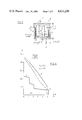
- FIG. 6 shows a diagram of the evolution of the forces of attraction and of the resistant forces met with by an electromagnet in accordance with the invention, when it is applied to a small contactor;
- FIG. 8 shows, for comparison purposes, a pot shaped electromagnet of the prior art
- FIG. 9 shows an electromagnet in accordance with the invention, in which the increase in the area of the working air gap has been obtained in ways different from the preceding ones;
- FIG. 10 shows one example of the measures which may be taken for reducing the reluctance of the closure air gap
- FIG. 11 shows, in an external elevational view, an electromagnet in which the reluctance of the closure air gap develops during the travel of the armature
- FIGS. 12 and 13 illustrate, in an external elevational view and, respectively, in a top view in section through plane TT', an electromagnet having the same properties as the preceding one, but in which the evolution of the reluctance may be chosen from one of two possible evolutions.
- An electromagnet 1' in accordance with the invention and shown in FIG. 1 has two magnetizable pieces of revolution 2, 3 moveable with respect to each other along a common axis of revolution XX', and engaged one in the other. These pieces once engaged have the appearance of a pot whose inner volume 18 is occupied by a coil 4 having current lead-ins 5, 6 which pass for example through the piece 3 considered here as being fixed, whereas the reverse would also be possible.
- Piece 3 comprises a substantially flat bottom 7 in the center of which projects a cylindrical core 8 having on its outer surface a thin layer 9 of an amagnetic material with good friction properties.
- An annular skirt 10 outwardly extends the bottom parallel to the core and comprises at its free end a conical surface 11 of revolution forming an angle ⁇ with the axis.
- the second piece 2 which is therefore here assumed moveable, has a shape comparable to that of piece 3, but comprises in the center of its bottom 16 a tubular extension 12 whose bore 13 has core 8 passing therethrough and slides thereover with an easy fit, whereas its short skirt 14 has a conical surface 15 of angle ⁇ which is parallel to the preceding one, opposite which it is situated.
- a return spring 17 which, by way of example, has been disposed inside volume 18 between pieces 2 and 3, but which could be placed outside, imparts to piece 3 a force returning it to a rest position in which it comes up against a stop 19 and in which a distance "c" equal to the relative travel of pieces 2 and 3 separates the conical surfaces parallel to axis XX'.
- the mobile piece 2 which will henceforth be called armature, may be mechanically coupled to any piece or device for communicating thereto a movement of an amplitude equal to "c" which, in order to occur, requires the ampere turns flowing in the coil to be sufficient to overcome, first of all an initial resistant force, by means of an initial pulling force developed by the attraction of the armature, and are then used efficiently for overcoming other resistant forces which appear during the movement, for example for operating the compression of pressure springs, if the armature is associated with mobile switch contacts (not shown).
- ampere turns developed by a coil are essentially used for magnetizing, on the one hand, the working air gap E which separates the conical pole surfaces and, on the other hand, the inevitable closure air gap --e-- through which the magnetic flux must pass.
- the initial induction B i in air gap E, as well as the dimensions of pull surfaces 15 and 11, must themselves be sufficient for the initial pulling force f i to be greater than the initial resistant forces R i .
- an electromagnet capable of developing such a pulling force when a travel "c" must be effected while overcoming initial resistant forces whose subsequent variation is known in advance, may be obtained without difficulty by known means and known calculation, when the power and the volume which the electromagnet can have are not subjected to any particular restriction.
- an electromagnet supplied by a DC current for the volume of this latter is generally greater by about 50%, or to limit the power of an electromagnet, for example to a power of a half Watt, while requiring it to develop initial attraction forces of the order of 100 cN, while then travelling over a distance of the order of 3 to 4 mm.
- FIG. 2 Another electromagnet 1'a, shown in FIG. 2, in which the same references refer to elements having the same functions, is directly derived from the preceding one by reversing the position of core 8' and the tubular extension 12' which are now connected to armature 2' and to the yoke pot 3'.
- the axial length along which the air gap --e--, respectively --e'-- extends will be as large as possible for reasons explained further on; in all cases, this length will always be close to the height --H-- of coil 4.
- the electromagnet 1b shown in FIG. 3 shows how the position of the working air gap E b may be modified in one or other of the embodiments illustrated in FIG. 1 or 2, by bringing this air gap close to the bottom 7b of the fixed yoke 3b so as to reduce the leak fluxes which might not cooperate in the attraction of the armature; skirt 14' of the mobile armature 2b is here longer than in the preceding case while skirt 10' is on the other hand shorter.
- FIG. 4 Another electromagnet 1" in accordance with the invention, and shown in FIG. 4 comprises a fixed yoke 20 which is formed by the assembly of two magnetizable pieces of revolution 21 and 22, a mobile magnetizable armature 23, a coil 24 and a spring 17'.
- yoke 20 retains, in an inner volume 80, the coil which has been previously fitted about a solid core 25 of piece 21 concentric with and secured to a bottom 26 having at its periphery a slanting surface 81 forming an angle ⁇ with axis YY'.
- the free end 27 of the core is here anchored in the flat bottom 28 of piece 22, which is extended by an annular skirt 29 whose surface is preferably coated with a fine layer of amagnetic antifriction material 30 and which extends parallel to core 25.
- the mobile armature 23 has the form of a ring whose cylindrical inner surface 31 slides with an appropriate clearance over layer 30 and one end of which placed opposite surface 81 has a parallel tapered surface 32; the length "m" of this armature is preferably greater than the height "h" of skirt 29, for allowing it to slide without the contact surface being reduced and so the reluctance increased; it will be seen further on that certain modifications may however be made to the value thereof so as to comply with particular objectives. It can be seen that, with this arrangement, the whole of the internal volume 80 of yoke 20 is occupied by the coil 24.
- the ampere turns --ni-- developped by the coil when it has the current flowing therethrough cause a flux ⁇ to develop which will flow through the magnetizable pieces, while passing on the one hand, through a working air gap placed between the tapered surfaces 81, 32, respectively 11, 15 and whose dimension is --E-- and, on the other, through a closure air gap which is materialized by the thickness --e-- of the layer of antifriction material.
- the air gap E whose area is --s-- and the air gap --e--- whose area is --S--, define reluctances R 1 and R 2 which give to the flux a value ⁇ causing inductions B 1 and B 2 to appear.
- the reluctance R 2 is provided for the reluctance R 2 to be as small as possible will respect to reluctance R 1 when the armature is in the open position and so that the product of the square of the initial induction B 1 multiplied by the surface --s-- (or initial force of attraction -F i ) is as high as possible when the armatures are at rest, so as to easily overcome the initial resistant forces R i .
- this initial induction B 1 must be chosen so that the current attraction force is able to develop while remaining for example greater than the progressive or stepped resistant forces which are successively or simultaneously met with when the armature actuates mobile contacts of a contactor. In fact, if the initial induction were already high, the appearance of saturation in the magnetic circuit would cause a slow growth of the attraction forces when the armature moves.
- the initial attraction force Fi is given by: ##EQU2##
- the expression of the net useful force Fu then comprises a coefficient of the form (1-r/K 2 ) which shows, if need be, that this force is greater when the friction coefficient r is small and when K 2 is high.
- Simulations have allowed an evolution of the induction B 3 in the core to be chosen which is advantageously between 0.7 Tesla and 1.6 Tesla (i.e. a ratio close to 2) when the armature closes, this evolution being well adapted to the application to contactors.
- the invention may have other forms of embodiment which still place it within the desire to obtain an initial high force of attraction; instead of using slanting surfaces governed by cones, the pole surfaces of the working air gap could each have a series of teeth 50, respectively 51, with slanting sides, cooperating by penetration of projections of one in the gaps of the other; angular orientation means 52, 53, for example comprising an axial groove and a transverse pin, may then be necessary for preventing rotation of armature 54 with respect to yoke 55 at the time of energization of the coil, see FIG. 9.
- An increase in area S which the closure air gap must have (and so of K 2 ) may be obtained for example by means of an extension 59 of armature 60 cooperating with an extension 57 of skirt 61 belonging to yoke 58, see FIG. 10.
- the orientation chosen may be defined as that which causes a normal half straight line erected on a concave conical surface such as 15, respectively 81 (see FIG. 4) to pass in the vicinity of a central point O placed on the axis of symmetry XX', respectively YY'.
- cylindrical pot which has been used in the preceding examples, must not be limited to that of a cylinder of revolution which forms however the most advantageous embodiment thereof.
- right cylinders may also be considered whose external surface would be defined by the path of a straight line generatrix bearing on a directrix curve of figure different from a circle.
- electromagnet pots of a substantially prismatic shape or, in other words, pots of square or rectangular section with rounded edges, so as to increase the surfaces which limit the pulling air gap; the closure air gap may then be formed by means of an insulating layer in the form of a film which is bonded to the skirt of this pot and to a sliding armature having a corresponding section.
Landscapes
- Electromagnetism (AREA)
- Physics & Mathematics (AREA)
- Engineering & Computer Science (AREA)
- Power Engineering (AREA)
- Electromagnets (AREA)
- Relay Circuits (AREA)
- Push-Button Switches (AREA)
- Switches That Are Operated By Magnetic Or Electric Fields (AREA)
- Magnetic Treatment Devices (AREA)
- Hard Magnetic Materials (AREA)
- Motor Or Generator Current Collectors (AREA)
- Dc Machiner (AREA)
- Arc-Extinguishing Devices That Are Switches (AREA)
- Emergency Protection Circuit Devices (AREA)
- Switch Cases, Indication, And Locking (AREA)
- Switches With Compound Operations (AREA)
- Cookers (AREA)
- Brushes (AREA)
- Electronic Switches (AREA)
Abstract
Description
Claims (6)
Applications Claiming Priority (2)
| Application Number | Priority Date | Filing Date | Title |
|---|---|---|---|
| FR8411704 | 1984-07-24 | ||
| FR8411704A FR2568402B1 (en) | 1984-07-24 | 1984-07-24 | DIRECT CURRENT ELECTROMAGNET, PARTICULARLY FOR ELECTRIC SWITCHING APPARATUS |
Publications (1)
| Publication Number | Publication Date |
|---|---|
| US4633209A true US4633209A (en) | 1986-12-30 |
Family
ID=9306425
Family Applications (1)
| Application Number | Title | Priority Date | Filing Date |
|---|---|---|---|
| US06/756,622 Expired - Fee Related US4633209A (en) | 1984-07-24 | 1985-07-19 | DC electromagnet, in particular for an electric switching apparatus |
Country Status (10)
| Country | Link |
|---|---|
| US (1) | US4633209A (en) |
| EP (1) | EP0170562B1 (en) |
| JP (1) | JPH0785449B2 (en) |
| KR (1) | KR890002043B1 (en) |
| AT (1) | ATE34869T1 (en) |
| DE (1) | DE3563138D1 (en) |
| DK (1) | DK160380C (en) |
| ES (1) | ES8608721A1 (en) |
| FR (1) | FR2568402B1 (en) |
| NO (1) | NO168008C (en) |
Cited By (28)
| Publication number | Priority date | Publication date | Assignee | Title |
|---|---|---|---|---|
| US4688012A (en) * | 1986-09-22 | 1987-08-18 | International Business Machines Corporation | Electromagnetic actuator mechanism in particular for print hammer drives |
| GB2199698A (en) * | 1987-01-08 | 1988-07-13 | Colt Ind Inc | Electromagnet, valve assembly and fuel metering apparatus |
| US4783049A (en) * | 1986-03-24 | 1988-11-08 | Lectron Products, Inc. | Electrically operated automatic transmission controller assembly |
| US4812884A (en) * | 1987-06-26 | 1989-03-14 | Ledex Inc. | Three-dimensional double air gap high speed solenoid |
| US5010312A (en) * | 1990-04-10 | 1991-04-23 | Rostra Engineered Components | Solenoid actuators |
| US5066980A (en) * | 1988-09-01 | 1991-11-19 | Aeg Olympia Office Gmbh | Solenoid plunger magnet and its use as print hammer in a print hammer device |
| DE4244443A1 (en) * | 1992-12-23 | 1994-07-07 | Mannesmann Ag | Electromagnetic drive with magnet yoke carrying electromagnetic coil |
| DE4244444A1 (en) * | 1992-12-23 | 1994-07-07 | Mannesmann Ag | Electromagnetic valve with electric current feed for electromagnetic coil |
| DE4416500A1 (en) * | 1994-05-10 | 1995-11-23 | Binder Magnete | Magnet system for lifting apparatus |
| US5646588A (en) * | 1994-09-19 | 1997-07-08 | Caterpillar Inc. | Stroke elongation device for an electromagnetic actuator |
| US5717369A (en) * | 1996-05-03 | 1998-02-10 | Wilson; Arthur L. | Alternating current relay |
| DE29801860U1 (en) * | 1998-02-05 | 1998-03-19 | Kuhnke GmbH, 23714 Malente | Electromagnet |
| US5785298A (en) * | 1996-04-15 | 1998-07-28 | Teknocraft, Inc. | Proportional solenoid-controlled fluid valve assembly |
| US20020079472A1 (en) * | 1996-04-15 | 2002-06-27 | Kumar Viraraghavan S. | Proportional solenoid-controlled fluid valve having compact pressure-balancing armature-poppet assembly |
| US6604726B2 (en) | 1996-04-15 | 2003-08-12 | Teknocraft, Inc. | Proportional solenoid-controlled fluid valve assembly without non-magnetic alignment support element |
| US6827331B1 (en) * | 1999-11-09 | 2004-12-07 | Robert Bosch Gmbh | Electromagnetic actuator |
| US20050093664A1 (en) * | 2001-12-28 | 2005-05-05 | Arthur Lanni | Electromagnetic actuator having a high initial force and improved latching |
| US20050145812A1 (en) * | 2003-12-31 | 2005-07-07 | Kumar Viraraghavan S. | Solenoid valve and poppet assembly |
| US6950000B1 (en) | 2001-12-28 | 2005-09-27 | Abb Technology Ag | High initial force electromagnetic actuator |
| US20070194873A1 (en) * | 2006-02-17 | 2007-08-23 | Sarah Gibson | Actuator |
| US20080136266A1 (en) * | 2004-01-12 | 2008-06-12 | Siemens Aktiengesellschaft | Electromagnetic Linear Drive |
| US20090128271A1 (en) * | 2006-04-18 | 2009-05-21 | Shindengen Mechatronics Co., Ltd | Solenoid |
| US20090302980A1 (en) * | 2006-08-25 | 2009-12-10 | Siemens Aktiengesellschaft | Electromagnetic Drive Unit and an Electomechanical Switching Device |
| WO2012123538A1 (en) * | 2011-03-16 | 2012-09-20 | Eto Magnetic Gmbh | Electromagnetic actuator device |
| CN102714109A (en) * | 2009-12-04 | 2012-10-03 | Abb技术股份公司 | Magnetic actuator unit for a circuit-breaker arrangement |
| US20150061799A1 (en) * | 2012-03-28 | 2015-03-05 | Eaton Corporation | Solenoid assembly with anti-hysteresis feature |
| US20150279539A1 (en) * | 2014-04-01 | 2015-10-01 | The Boeing Company | Positioning system for an electromechanical actuator |
| DE102015214989A1 (en) * | 2015-08-06 | 2016-09-08 | Festo Ag & Co. Kg | Actuator and valve assembly |
Families Citing this family (6)
| Publication number | Priority date | Publication date | Assignee | Title |
|---|---|---|---|---|
| FR2664737B1 (en) * | 1990-07-13 | 1994-04-01 | Telemecanique | DIRECT CURRENT ELECTROMAGNET. |
| DE4108601C2 (en) * | 1991-03-18 | 1995-06-29 | Harting Elektronik Gmbh | Catch and hold magnet |
| DE10005953A1 (en) * | 2000-02-09 | 2001-08-16 | Heinz Leiber | Method of manufacturing an electromagnetic actuator and electromagnetic actuator |
| TWI469475B (en) * | 2008-11-17 | 2015-01-11 | Komatsu Ind Corp | A linear actuator |
| JP6831967B2 (en) * | 2016-12-15 | 2021-02-24 | 下西技研工業株式会社 | solenoid |
| JP2020017643A (en) * | 2018-07-26 | 2020-01-30 | 多摩川精機株式会社 | Cylindrical solenoid |
Citations (4)
| Publication number | Priority date | Publication date | Assignee | Title |
|---|---|---|---|---|
| US506282A (en) * | 1893-10-10 | Illitjs augustus timmis | ||
| US750132A (en) * | 1904-01-19 | Illius augustus timmis and edgar william timmis | ||
| US3378732A (en) * | 1965-04-15 | 1968-04-16 | Penn Controls | Electromagnetic actuator |
| US4491816A (en) * | 1981-12-14 | 1985-01-01 | Sprecher & Schuh Ag | Transducer for alternating current limiter |
Family Cites Families (4)
| Publication number | Priority date | Publication date | Assignee | Title |
|---|---|---|---|---|
| FR615035A (en) * | 1925-08-31 | 1926-12-28 | Improvements to electromagnets | |
| DE2111123A1 (en) * | 1971-03-09 | 1972-09-21 | Otello Baldi | Bearing of the armature of electromagnetic drives, in particular all types of electric actuating magnets |
| DE2112799B2 (en) * | 1971-03-17 | 1975-09-18 | Robert Bosch Gmbh, 7000 Stuttgart | Electromagnet |
| US4550302A (en) * | 1982-11-09 | 1985-10-29 | Matsushita Electric Industrial Co., Ltd. | Solenoid |
-
1984
- 1984-07-24 FR FR8411704A patent/FR2568402B1/en not_active Expired
-
1985
- 1985-06-25 DE DE8585401275T patent/DE3563138D1/en not_active Expired
- 1985-06-25 AT AT85401275T patent/ATE34869T1/en not_active IP Right Cessation
- 1985-06-25 EP EP85401275A patent/EP0170562B1/en not_active Expired
- 1985-07-18 NO NO852875A patent/NO168008C/en unknown
- 1985-07-19 US US06/756,622 patent/US4633209A/en not_active Expired - Fee Related
- 1985-07-22 DK DK333585A patent/DK160380C/en active
- 1985-07-23 ES ES545485A patent/ES8608721A1/en not_active Expired
- 1985-07-24 KR KR1019850005281A patent/KR890002043B1/en not_active IP Right Cessation
- 1985-07-24 JP JP60164990A patent/JPH0785449B2/en not_active Expired - Lifetime
Patent Citations (4)
| Publication number | Priority date | Publication date | Assignee | Title |
|---|---|---|---|---|
| US506282A (en) * | 1893-10-10 | Illitjs augustus timmis | ||
| US750132A (en) * | 1904-01-19 | Illius augustus timmis and edgar william timmis | ||
| US3378732A (en) * | 1965-04-15 | 1968-04-16 | Penn Controls | Electromagnetic actuator |
| US4491816A (en) * | 1981-12-14 | 1985-01-01 | Sprecher & Schuh Ag | Transducer for alternating current limiter |
Cited By (47)
| Publication number | Priority date | Publication date | Assignee | Title |
|---|---|---|---|---|
| US4783049A (en) * | 1986-03-24 | 1988-11-08 | Lectron Products, Inc. | Electrically operated automatic transmission controller assembly |
| US4688012A (en) * | 1986-09-22 | 1987-08-18 | International Business Machines Corporation | Electromagnetic actuator mechanism in particular for print hammer drives |
| GB2199698A (en) * | 1987-01-08 | 1988-07-13 | Colt Ind Inc | Electromagnet, valve assembly and fuel metering apparatus |
| GB2199698B (en) * | 1987-01-08 | 1991-06-19 | Colt Ind Inc | Electromagnetic actuator for a valve in a fuel supply system |
| US4812884A (en) * | 1987-06-26 | 1989-03-14 | Ledex Inc. | Three-dimensional double air gap high speed solenoid |
| US5066980A (en) * | 1988-09-01 | 1991-11-19 | Aeg Olympia Office Gmbh | Solenoid plunger magnet and its use as print hammer in a print hammer device |
| US5010312A (en) * | 1990-04-10 | 1991-04-23 | Rostra Engineered Components | Solenoid actuators |
| DE4244443C2 (en) * | 1992-12-23 | 1998-11-26 | Mannesmann Ag | Electromagnetic drive |
| DE4244443A1 (en) * | 1992-12-23 | 1994-07-07 | Mannesmann Ag | Electromagnetic drive with magnet yoke carrying electromagnetic coil |
| DE4244444A1 (en) * | 1992-12-23 | 1994-07-07 | Mannesmann Ag | Electromagnetic valve with electric current feed for electromagnetic coil |
| DE4416500C2 (en) * | 1994-05-10 | 2000-07-20 | Kendrion Binder Magnete Gmbh | DC solenoid |
| DE4416500A1 (en) * | 1994-05-10 | 1995-11-23 | Binder Magnete | Magnet system for lifting apparatus |
| US5646588A (en) * | 1994-09-19 | 1997-07-08 | Caterpillar Inc. | Stroke elongation device for an electromagnetic actuator |
| US5785298A (en) * | 1996-04-15 | 1998-07-28 | Teknocraft, Inc. | Proportional solenoid-controlled fluid valve assembly |
| US20020079472A1 (en) * | 1996-04-15 | 2002-06-27 | Kumar Viraraghavan S. | Proportional solenoid-controlled fluid valve having compact pressure-balancing armature-poppet assembly |
| US6604726B2 (en) | 1996-04-15 | 2003-08-12 | Teknocraft, Inc. | Proportional solenoid-controlled fluid valve assembly without non-magnetic alignment support element |
| US6715732B2 (en) | 1996-04-15 | 2004-04-06 | Teknocraft, Inc. | Proportional solenoid-controlled fluid valve assembly |
| US7028978B2 (en) | 1996-04-15 | 2006-04-18 | Kumar Viraraghavan S | Proportional solenoid-controlled fluid valve having compact pressure-balancing armature-poppet assembly |
| US5717369A (en) * | 1996-05-03 | 1998-02-10 | Wilson; Arthur L. | Alternating current relay |
| DE29801860U1 (en) * | 1998-02-05 | 1998-03-19 | Kuhnke GmbH, 23714 Malente | Electromagnet |
| DE19901679B4 (en) * | 1998-02-05 | 2008-08-28 | Kuhnke Gmbh | electromagnet |
| US6827331B1 (en) * | 1999-11-09 | 2004-12-07 | Robert Bosch Gmbh | Electromagnetic actuator |
| US6950000B1 (en) | 2001-12-28 | 2005-09-27 | Abb Technology Ag | High initial force electromagnetic actuator |
| US7053742B2 (en) * | 2001-12-28 | 2006-05-30 | Abb Technology Ag | Electromagnetic actuator having a high initial force and improved latching |
| US20050093664A1 (en) * | 2001-12-28 | 2005-05-05 | Arthur Lanni | Electromagnetic actuator having a high initial force and improved latching |
| US20050145812A1 (en) * | 2003-12-31 | 2005-07-07 | Kumar Viraraghavan S. | Solenoid valve and poppet assembly |
| US20080136266A1 (en) * | 2004-01-12 | 2008-06-12 | Siemens Aktiengesellschaft | Electromagnetic Linear Drive |
| US7626288B2 (en) * | 2004-01-12 | 2009-12-01 | Siemens Aktiengesellschaft | Electromagnetic linear drive |
| US20070194873A1 (en) * | 2006-02-17 | 2007-08-23 | Sarah Gibson | Actuator |
| US7876187B2 (en) | 2006-02-17 | 2011-01-25 | Rolls-Royce Plc | Actuator |
| US20090128271A1 (en) * | 2006-04-18 | 2009-05-21 | Shindengen Mechatronics Co., Ltd | Solenoid |
| US20090302980A1 (en) * | 2006-08-25 | 2009-12-10 | Siemens Aktiengesellschaft | Electromagnetic Drive Unit and an Electomechanical Switching Device |
| US8269589B2 (en) * | 2006-08-25 | 2012-09-18 | Siemens Aktiengesellschaft | Electromagnetic drive unit and an electromechanical switching device |
| US20120268223A1 (en) * | 2009-12-04 | 2012-10-25 | Abb Technology Ag | Magnetic actuator unit for a circuit-breaker arrangement |
| RU2554075C2 (en) * | 2009-12-04 | 2015-06-27 | Абб Текнолоджи Аг | Magnetic drive of automatic breaker |
| CN102714109A (en) * | 2009-12-04 | 2012-10-03 | Abb技术股份公司 | Magnetic actuator unit for a circuit-breaker arrangement |
| US9053882B2 (en) * | 2009-12-04 | 2015-06-09 | Abb Technology Ag | Magnetic actuator unit for a circuit-breaker arrangement |
| AU2010327027B2 (en) * | 2009-12-04 | 2014-09-04 | Abb Technology Ag | Magnetic actuator unit for a circuit-breaker arrangement |
| CN103443877A (en) * | 2011-03-16 | 2013-12-11 | Eto电磁有限责任公司 | Electromagnetic actuator device |
| WO2012123538A1 (en) * | 2011-03-16 | 2012-09-20 | Eto Magnetic Gmbh | Electromagnetic actuator device |
| US9117583B2 (en) | 2011-03-16 | 2015-08-25 | Eto Magnetic Gmbh | Electromagnetic actuator device |
| CN103443877B (en) * | 2011-03-16 | 2017-06-09 | Eto电磁有限责任公司 | Electromagnetic actuator device |
| US20150061799A1 (en) * | 2012-03-28 | 2015-03-05 | Eaton Corporation | Solenoid assembly with anti-hysteresis feature |
| US9324488B2 (en) * | 2012-03-28 | 2016-04-26 | Eaton Corporation | Solenoid assembly |
| US20150279539A1 (en) * | 2014-04-01 | 2015-10-01 | The Boeing Company | Positioning system for an electromechanical actuator |
| US9412507B2 (en) * | 2014-04-01 | 2016-08-09 | The Boeing Company | Positioning system for an electromechanical actuator |
| DE102015214989A1 (en) * | 2015-08-06 | 2016-09-08 | Festo Ag & Co. Kg | Actuator and valve assembly |
Also Published As
| Publication number | Publication date |
|---|---|
| EP0170562B1 (en) | 1988-06-01 |
| NO168008B (en) | 1991-09-23 |
| KR860001497A (en) | 1986-02-26 |
| KR890002043B1 (en) | 1989-06-08 |
| ATE34869T1 (en) | 1988-06-15 |
| FR2568402B1 (en) | 1987-02-20 |
| JPH0785449B2 (en) | 1995-09-13 |
| DK333585A (en) | 1986-01-25 |
| DK160380B (en) | 1991-03-04 |
| NO852875L (en) | 1986-01-27 |
| ES8608721A1 (en) | 1986-06-16 |
| FR2568402A1 (en) | 1986-01-31 |
| DE3563138D1 (en) | 1988-07-07 |
| DK160380C (en) | 1991-08-12 |
| DK333585D0 (en) | 1985-07-22 |
| NO168008C (en) | 1992-01-02 |
| EP0170562A1 (en) | 1986-02-05 |
| JPS6140010A (en) | 1986-02-26 |
| ES545485A0 (en) | 1986-06-16 |
Similar Documents
| Publication | Publication Date | Title |
|---|---|---|
| US4633209A (en) | DC electromagnet, in particular for an electric switching apparatus | |
| US3460081A (en) | Electromagnetic actuator with permanent magnets | |
| US6870454B1 (en) | Linear switch actuator | |
| EP0506799B1 (en) | Magnetic drive with permanent-magnet solenoid armature | |
| US6489870B1 (en) | Solenoid with improved pull force | |
| US6496092B1 (en) | Electromagnetic drive | |
| EP0198085B1 (en) | Electromagnetic actuator | |
| US4664355A (en) | Double-acting magnetic valve | |
| US7078833B2 (en) | Force motor with increased proportional stroke | |
| JP2638651B2 (en) | Operating device for gas exchange valve | |
| JPH02208905A (en) | Solernoid actuator | |
| US4797645A (en) | Electromagnetic actuator | |
| EP0179911A1 (en) | Electromagnetic actuator apparatus | |
| US5281939A (en) | Multiple pole solenoid using simultaneously energized AC and DC coils | |
| US20200332915A1 (en) | Dual coil solenoid valve for a fuel gas control valve and the control method thereof | |
| US5200728A (en) | Solenoid device | |
| SU1121469A1 (en) | Working unit of electromagnetic actuating gear of internal combustion engine gas distribution valves | |
| US3774058A (en) | Force transducer | |
| US4692729A (en) | Direct current electromagnet having a movement of translation | |
| US2999193A (en) | Actuator magnet assembly | |
| US4564828A (en) | Electromagnetic relay | |
| SU1453544A1 (en) | Electromagnetic reciprocation drive | |
| JPS61200386A (en) | electromagnetic pump | |
| SU888219A1 (en) | Electromagnetic | |
| US3414852A (en) | Magnetic latching relay |
Legal Events
| Date | Code | Title | Description |
|---|---|---|---|
| AS | Assignment |
Owner name: LA TELEMECANIQUE ELECTRIQUE, 33 BIS, AVENUE DU MAR Free format text: ASSIGNMENT OF ASSIGNORS INTEREST.;ASSIGNORS:BELBEL, ELIE;BATAILLE, CHRISTIAN;LAURAIRE, MICHEL;REEL/FRAME:004432/0981 Effective date: 19850611 |
|
| FEPP | Fee payment procedure |
Free format text: PAYOR NUMBER ASSIGNED (ORIGINAL EVENT CODE: ASPN); ENTITY STATUS OF PATENT OWNER: LARGE ENTITY |
|
| FPAY | Fee payment |
Year of fee payment: 4 |
|
| FEPP | Fee payment procedure |
Free format text: PAYOR NUMBER ASSIGNED (ORIGINAL EVENT CODE: ASPN); ENTITY STATUS OF PATENT OWNER: LARGE ENTITY Free format text: PAYER NUMBER DE-ASSIGNED (ORIGINAL EVENT CODE: RMPN); ENTITY STATUS OF PATENT OWNER: LARGE ENTITY |
|
| FEPP | Fee payment procedure |
Free format text: PAYOR NUMBER ASSIGNED (ORIGINAL EVENT CODE: ASPN); ENTITY STATUS OF PATENT OWNER: LARGE ENTITY Free format text: PAYER NUMBER DE-ASSIGNED (ORIGINAL EVENT CODE: RMPN); ENTITY STATUS OF PATENT OWNER: LARGE ENTITY |
|
| FPAY | Fee payment |
Year of fee payment: 8 |
|
| FEPP | Fee payment procedure |
Free format text: PAYER NUMBER DE-ASSIGNED (ORIGINAL EVENT CODE: RMPN); ENTITY STATUS OF PATENT OWNER: LARGE ENTITY |
|
| FEPP | Fee payment procedure |
Free format text: PAYOR NUMBER ASSIGNED (ORIGINAL EVENT CODE: ASPN); ENTITY STATUS OF PATENT OWNER: LARGE ENTITY |
|
| REMI | Maintenance fee reminder mailed | ||
| LAPS | Lapse for failure to pay maintenance fees | ||
| FP | Lapsed due to failure to pay maintenance fee |
Effective date: 19981230 |
|
| STCH | Information on status: patent discontinuation |
Free format text: PATENT EXPIRED DUE TO NONPAYMENT OF MAINTENANCE FEES UNDER 37 CFR 1.362 |