US4619030A - Temperature control - Google Patents
Temperature control Download PDFInfo
- Publication number
- US4619030A US4619030A US06/753,336 US75333685A US4619030A US 4619030 A US4619030 A US 4619030A US 75333685 A US75333685 A US 75333685A US 4619030 A US4619030 A US 4619030A
- Authority
- US
- United States
- Prior art keywords
- specimen
- heat sink
- temperature
- radiation
- drum
- Prior art date
- Legal status (The legal status is an assumption and is not a legal conclusion. Google has not performed a legal analysis and makes no representation as to the accuracy of the status listed.)
- Expired - Fee Related
Links
- 230000005855 radiation Effects 0.000 claims description 16
- 238000000034 method Methods 0.000 claims description 5
- 230000004907 flux Effects 0.000 abstract description 3
- 235000012431 wafers Nutrition 0.000 description 26
- 238000010884 ion-beam technique Methods 0.000 description 7
- XUIMIQQOPSSXEZ-UHFFFAOYSA-N Silicon Chemical compound [Si] XUIMIQQOPSSXEZ-UHFFFAOYSA-N 0.000 description 4
- 229910052710 silicon Inorganic materials 0.000 description 4
- 239000010703 silicon Substances 0.000 description 4
- 239000002826 coolant Substances 0.000 description 2
- 238000010521 absorption reaction Methods 0.000 description 1
- QVGXLLKOCUKJST-UHFFFAOYSA-N atomic oxygen Chemical compound [O] QVGXLLKOCUKJST-UHFFFAOYSA-N 0.000 description 1
- 230000004888 barrier function Effects 0.000 description 1
- 230000000295 complement effect Effects 0.000 description 1
- 230000000694 effects Effects 0.000 description 1
- 239000012530 fluid Substances 0.000 description 1
- 150000002500 ions Chemical class 0.000 description 1
- 239000007788 liquid Substances 0.000 description 1
- 238000004519 manufacturing process Methods 0.000 description 1
- 230000004048 modification Effects 0.000 description 1
- 238000012986 modification Methods 0.000 description 1
- 229910052760 oxygen Inorganic materials 0.000 description 1
- 239000001301 oxygen Substances 0.000 description 1
- 125000004430 oxygen atom Chemical group O* 0.000 description 1
- 239000004065 semiconductor Substances 0.000 description 1
Images

Classifications
-
- F—MECHANICAL ENGINEERING; LIGHTING; HEATING; WEAPONS; BLASTING
- F28—HEAT EXCHANGE IN GENERAL
- F28F—DETAILS OF HEAT-EXCHANGE AND HEAT-TRANSFER APPARATUS, OF GENERAL APPLICATION
- F28F27/00—Control arrangements or safety devices specially adapted for heat-exchange or heat-transfer apparatus
-
- H—ELECTRICITY
- H01—ELECTRIC ELEMENTS
- H01J—ELECTRIC DISCHARGE TUBES OR DISCHARGE LAMPS
- H01J37/00—Discharge tubes with provision for introducing objects or material to be exposed to the discharge, e.g. for the purpose of examination or processing thereof
- H01J37/02—Details
- H01J37/20—Means for supporting or positioning the object or the material; Means for adjusting diaphragms or lenses associated with the support
-
- H—ELECTRICITY
- H01—ELECTRIC ELEMENTS
- H01J—ELECTRIC DISCHARGE TUBES OR DISCHARGE LAMPS
- H01J2237/00—Discharge tubes exposing object to beam, e.g. for analysis treatment, etching, imaging
- H01J2237/20—Positioning, supporting, modifying or maintaining the physical state of objects being observed or treated
- H01J2237/2001—Maintaining constant desired temperature
-
- Y—GENERAL TAGGING OF NEW TECHNOLOGICAL DEVELOPMENTS; GENERAL TAGGING OF CROSS-SECTIONAL TECHNOLOGIES SPANNING OVER SEVERAL SECTIONS OF THE IPC; TECHNICAL SUBJECTS COVERED BY FORMER USPC CROSS-REFERENCE ART COLLECTIONS [XRACs] AND DIGESTS
- Y10—TECHNICAL SUBJECTS COVERED BY FORMER USPC
- Y10S—TECHNICAL SUBJECTS COVERED BY FORMER USPC CROSS-REFERENCE ART COLLECTIONS [XRACs] AND DIGESTS
- Y10S165/00—Heat exchange
- Y10S165/904—Radiation
-
- Y—GENERAL TAGGING OF NEW TECHNOLOGICAL DEVELOPMENTS; GENERAL TAGGING OF CROSS-SECTIONAL TECHNOLOGIES SPANNING OVER SEVERAL SECTIONS OF THE IPC; TECHNICAL SUBJECTS COVERED BY FORMER USPC CROSS-REFERENCE ART COLLECTIONS [XRACs] AND DIGESTS
- Y10—TECHNICAL SUBJECTS COVERED BY FORMER USPC
- Y10T—TECHNICAL SUBJECTS COVERED BY FORMER US CLASSIFICATION
- Y10T29/00—Metal working
- Y10T29/49—Method of mechanical manufacture
- Y10T29/49758—During simulated operation or operating conditions
- Y10T29/4976—Temperature
-
- Y—GENERAL TAGGING OF NEW TECHNOLOGICAL DEVELOPMENTS; GENERAL TAGGING OF CROSS-SECTIONAL TECHNOLOGIES SPANNING OVER SEVERAL SECTIONS OF THE IPC; TECHNICAL SUBJECTS COVERED BY FORMER USPC CROSS-REFERENCE ART COLLECTIONS [XRACs] AND DIGESTS
- Y10—TECHNICAL SUBJECTS COVERED BY FORMER USPC
- Y10T—TECHNICAL SUBJECTS COVERED BY FORMER US CLASSIFICATION
- Y10T29/00—Metal working
- Y10T29/53—Means to assemble or disassemble
- Y10T29/53039—Means to assemble or disassemble with control means energized in response to activator stimulated by condition sensor
- Y10T29/53061—Responsive to work or work-related machine element
Definitions
- the present invention relates to a method and an apparatus for controlling the temperature of a specimen undergoing treatment in an evacuated chamber.
- silicon wafers may be treated with a beam of ions in an evacuated chamber to bring about a desired modification of the surface.
- heat is generated in the wafer, and this heat may have to be transmitted to the surroundings if an unacceptable temperature rise is to be avoided.
- an apparatus for controlling the temperature of a specimen undergoing treatment in an evacuated chamber comprising means to support the specimen, at least one heat sink adjacent to but spaced from the specimen, and means situated between the specimen and the heat sink for varying the rate of heat transfer therebetween by radiation.
- the heat sink has a surface facing the specimen with a high emissivity in the range of wavelengths emitted by the specimen, as this maximises the rate of absorption of thermal radiation by the heat sink.
- the radiation varying means may comprise a plurality of elements, each element having a surface highly reflective to thermal radiation, the elements being movable so as to cover a larger or smaller fraction of the high emissivity surface of the heat sink.
- the movable elements are thin vanes, rotatable between orientations perpendicular or parallel to the surface of the heat sink.
- the support means is rotatable so as to cause the specimen to pass repeatedly through the region at which the treatment occurs, and to pass repeatedly adjacent to but spaced from the heat sink
- the radiation varying means comprises a vane with a surface highly reflective to thermal radiation, the vane being movable so as to cover a larger or smaller fraction of the high emissivity surface of the heat sink.
- the support means may be a hollow cylindrical drum rotatable about its longitudinal axis, and concentric cylindrical heat sinks may be provided both inside and outside the drum.
- the apparatus may include means for exposing the specimen to thermal radiation so as to raise its temperature.
- the invention also provides a method for controlling the temperature of a specimen undergoing treatment in an evacuated chamber, the method comprising supporting the specimen adjacent to but spaced from a heat sink, and varying the effective thermal emissivity of the surface of the heat sink onto which radiation from the specimen is incident in relation to the temperature of the specimen.
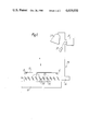
- FIG. 1 shows a diagrammatic side elevation of an apparatus for treating a silicon wafer, including a temperature control apparatus
- FIG. 2 shows a diagrammatic cross-sectional view of an alternative wafer treatment apparatus including a temperature control apparatus.
- a silicon wafer 10 is shown supported by two supports 12 in an evacuate chamber (not shown), so as to be irradiated by an oxygen ion beam A incident in the downwards direction.
- the ion beam A is scanned over the surface of the wafer 10, causing an increase in temperature, and embedding oxygen atoms in the wafer 10.
- the temperature is preferably maintained constant to within about 10K, at a value of about 500° C.
- the wafer 10 is supported above a heat sink 14 whose upper surface 16 is blackened so as to have a high emissivity to infra-red radiation.
- the heat sink 14 is cooled by a coolant liquid.
- Between the wafer 10 and the surface 16 of the heat sink 14 are a number of rectangular vanes 20 aligned parallel to each other and pivoted about parallel shafts 22. Both surfaces 24 of each vane 20 are made to be shiny and highly reflective to infra-red radiation.
- a drive mechanism 26 (shown diagrammatically) is connected to all the shafts 22 so as to rotate all the vanes 20 in unison to any desired orientation between perpendicular to and parallel to the surface 16 of the heat sink 14.
- the vanes 20 are of such a width that when parallel to the surface 16 of the heat sink 14 there are no gaps between adjacent vanes 20.
- the heat sink 14, the vanes 20 and the drive mechanism 26 are components of a temperature control apparatus 28 which also includes an infra-red detector 30 for measuring the temperature of the wafer 10, and a computer 32 connected to the detector 30 and to the drive mechanism 26.
- a lamp 34 is also connected to the computer 32.
- a wafer 10 is placed on the supports 12 and by means of the lamp 34 is heated initially to the desired temperature. Bombardment by the ion beam is then commenced, and the orientation of the vanes 20 is controlled by the computer 32 in accordance with the temperature of the wafer 10 as measured by the detector 30, so as to maintain the desired temperature.
- the vanes 20 are oriented perpendicular to the surface 16 of the heat sink 14 they have minimal effect on the radiant heat flux from the wafer 10 to the surface 16 of the heat sink 14, whereas when oriented parallel to the surface 16 of the heat sink 14 they substantially prevent any radiant heat flux.
- the rate of heat loss from the lower surface of the wafer 10 can therefore be controlled by rotation of the vanes 20, and hence a constant temperture maintained.
- an alternative temperature control apparatus may include alternative means for providing a reflective barrier of variable effective area between the wafer 10 and the heat sink 14; for example two plane reflective gratings slidable with respect to each other, the reflective portions of the one grating being complementary to that of the other grating.
- a large number of silicon wafers 40 are supported on the inside surface of a cylindrical hollow drum 42 which in use is rotated so as to pass the wafers 40 repeatedly through the path of an ion beam B.
- the beam B is thus effectively scanned over a large area--the whole inner surface of the drum 42--and the mean power received by any one wafer 40 is consequently less than with the apparatus of FIG. 1.
- the temperature of any one of the wafers 40, at equilibrium, is such that the energy gained during its passage through the ion beam B is lost to the surroundings by radiation during the rest of the revolution of the drum 42, and so the equilibrium temperature depends on the average thermal emissivity of all the surfaces adjacent to which the wafer 40 passes during a revolution of the drum 42.
- the temperature is controlled by means of two stationary cylindrical heat sinks 44 and 46, concentric with the drum 42 and respectively inside and outside the drum 42; and two half-cylindrical vanes 48 and 50, pivotably supported in the annular gaps between the drum 42 and the heat sink 44 or 46 respectively.
- the heat sinks 44 and 46 are maintained at a substantially constant temperature by passing a coolant fluid through them.
- the ion beam B emerges through a slot 52 in the wall of the inner heat sink 44.
- the surfaces of the heat sinks 44 and 46 facing the drum 42 below the horizontal plane P--P are blackened so as to provide surfaces with high emissivity at the wavelengths emitted by the drum 42 and the wafers 40; while the heat sink surfaces facing the drum 42 above the plane P--P are polished so as to provide low emissivity surfaces.
- the surfaces of the vanes 48 and 50 facing the drum 42 are polished, while the surfaces of the vanes 48 and 50 facing the respective heat sink 44 or 46 are blackened.
- the vanes 48 and 50 are supported by a common shaft (not shown) so as to be turnable together through about 180° between a position at which they shield the drum 42 and the wafers 40 from the blackened lower half of the heat sinks 44 and 46, to a position at which the blackened surfaces of the heat sinks 44 and 46 are fully exposed.
- Typical values for the total emissivity of blackened and polished surfaces are 0.8 and 0.1 respectively, and thus in operation of the apparatus of FIG. 2 the average emissivity of the surfaces adjacent to which a wafer 40 passes in each revolution of the drum 42 can be varied between about 0.1 and 0.5 by moving the vanes 48 and 50 between their extreme positions. Movement of the vanes 48 and 50 is brought about in dependance on the wafer temperature as measured by an infra-red detector (not shown), the control system being similar to that described above with reference to FIG. 1.
- non-uniformity of temperature of the wafers 40 may be compensated for by having appropriately curved leading and trailing edges to the half-cylindrical vanes 48 and 50.
Landscapes
- Engineering & Computer Science (AREA)
- Physics & Mathematics (AREA)
- Thermal Sciences (AREA)
- Mechanical Engineering (AREA)
- General Engineering & Computer Science (AREA)
- Chemical & Material Sciences (AREA)
- Analytical Chemistry (AREA)
- Inorganic Insulating Materials (AREA)
- Control Of Temperature (AREA)
- Valve Device For Special Equipments (AREA)
- Testing Or Measuring Of Semiconductors Or The Like (AREA)
- Physical Vapour Deposition (AREA)
Abstract
Description
Claims (8)
Applications Claiming Priority (2)
| Application Number | Priority Date | Filing Date | Title |
|---|---|---|---|
| GB848418062A GB8418062D0 (en) | 1984-07-16 | 1984-07-16 | Temperature control |
| GB8418062 | 1984-07-16 |
Publications (1)
| Publication Number | Publication Date |
|---|---|
| US4619030A true US4619030A (en) | 1986-10-28 |
Family
ID=10563953
Family Applications (1)
| Application Number | Title | Priority Date | Filing Date |
|---|---|---|---|
| US06/753,336 Expired - Fee Related US4619030A (en) | 1984-07-16 | 1985-07-09 | Temperature control |
Country Status (3)
| Country | Link |
|---|---|
| US (1) | US4619030A (en) |
| JP (1) | JPS6193825A (en) |
| GB (2) | GB8418062D0 (en) |
Cited By (5)
| Publication number | Priority date | Publication date | Assignee | Title |
|---|---|---|---|---|
| EP0325575A2 (en) * | 1988-01-22 | 1989-07-26 | IMS Ionen Mikrofabrikations Systeme Gesellschaft m.b.H. | Device for stabilizing an illuminated mask |
| US5044260A (en) * | 1990-06-21 | 1991-09-03 | Cts Consolidated Technical Services, Inc. | Air distribution unit |
| US5522215A (en) * | 1993-10-18 | 1996-06-04 | Dainippon Screen Mfg. Co., Ltd. | Substrate cooling apparatus |
| US6351952B1 (en) | 2000-12-19 | 2002-03-05 | Goodfaith Innovations, Inc. | Interruptible thermal bridge system |
| US6622515B2 (en) | 2000-12-19 | 2003-09-23 | Itb Solutions Llc | Interruptible thermal bridge system |
Families Citing this family (2)
| Publication number | Priority date | Publication date | Assignee | Title |
|---|---|---|---|---|
| JPH0728770B2 (en) * | 1987-11-24 | 1995-04-05 | タカラベルモント株式会社 | Hair treatment promotion equipment |
| JP6140539B2 (en) * | 2013-06-13 | 2017-05-31 | 株式会社アルバック | Vacuum processing equipment |
Citations (6)
| Publication number | Priority date | Publication date | Assignee | Title |
|---|---|---|---|---|
| US3062941A (en) * | 1959-12-14 | 1962-11-06 | Purdue Research Foundation | Radiation-sensitive infrared control |
| US3139881A (en) * | 1962-05-29 | 1964-07-07 | Hupp Corp | Infrared chicken brooder |
| US3174537A (en) * | 1959-06-30 | 1965-03-23 | Thompson Ramo Wooldridge Inc | Electromagnetic radiant energy response apparatus |
| US3225820A (en) * | 1962-11-01 | 1965-12-28 | Gen Precision Inc | Device for controlling temperature by heat conduction |
| US3682643A (en) * | 1969-07-15 | 1972-08-08 | Lawrence H Foster | Method for cooking foods using infrared radiation |
| US4319125A (en) * | 1979-07-20 | 1982-03-09 | Prince Fred J | Infra-red radiant heater system |
Family Cites Families (1)
| Publication number | Priority date | Publication date | Assignee | Title |
|---|---|---|---|---|
| GB2039387B (en) * | 1979-01-15 | 1983-02-23 | Pye Ltd | Automatic electrical control of temperature |
-
1984
- 1984-07-16 GB GB848418062A patent/GB8418062D0/en active Pending
-
1985
- 1985-07-08 GB GB08517285A patent/GB2163898B/en not_active Expired
- 1985-07-09 US US06/753,336 patent/US4619030A/en not_active Expired - Fee Related
- 1985-07-15 JP JP60155878A patent/JPS6193825A/en active Pending
Patent Citations (6)
| Publication number | Priority date | Publication date | Assignee | Title |
|---|---|---|---|---|
| US3174537A (en) * | 1959-06-30 | 1965-03-23 | Thompson Ramo Wooldridge Inc | Electromagnetic radiant energy response apparatus |
| US3062941A (en) * | 1959-12-14 | 1962-11-06 | Purdue Research Foundation | Radiation-sensitive infrared control |
| US3139881A (en) * | 1962-05-29 | 1964-07-07 | Hupp Corp | Infrared chicken brooder |
| US3225820A (en) * | 1962-11-01 | 1965-12-28 | Gen Precision Inc | Device for controlling temperature by heat conduction |
| US3682643A (en) * | 1969-07-15 | 1972-08-08 | Lawrence H Foster | Method for cooking foods using infrared radiation |
| US4319125A (en) * | 1979-07-20 | 1982-03-09 | Prince Fred J | Infra-red radiant heater system |
Cited By (6)
| Publication number | Priority date | Publication date | Assignee | Title |
|---|---|---|---|---|
| EP0325575A2 (en) * | 1988-01-22 | 1989-07-26 | IMS Ionen Mikrofabrikations Systeme Gesellschaft m.b.H. | Device for stabilizing an illuminated mask |
| EP0325575A3 (en) * | 1988-01-22 | 1990-08-29 | Ims Ionen Mikrofabrikations Systeme Gesellschaft M.B.H. | Device for stabilizing an illuminated mask |
| US5044260A (en) * | 1990-06-21 | 1991-09-03 | Cts Consolidated Technical Services, Inc. | Air distribution unit |
| US5522215A (en) * | 1993-10-18 | 1996-06-04 | Dainippon Screen Mfg. Co., Ltd. | Substrate cooling apparatus |
| US6351952B1 (en) | 2000-12-19 | 2002-03-05 | Goodfaith Innovations, Inc. | Interruptible thermal bridge system |
| US6622515B2 (en) | 2000-12-19 | 2003-09-23 | Itb Solutions Llc | Interruptible thermal bridge system |
Also Published As
| Publication number | Publication date |
|---|---|
| GB8418062D0 (en) | 1984-08-22 |
| GB2163898A (en) | 1986-03-05 |
| GB2163898B (en) | 1988-08-03 |
| JPS6193825A (en) | 1986-05-12 |
| GB8517285D0 (en) | 1985-08-14 |
Similar Documents
| Publication | Publication Date | Title |
|---|---|---|
| JP2961123B2 (en) | Rapid heat treatment of semiconductor disks by electromagnetic radiation. | |
| KR100700236B1 (en) | Gas-Driven Rotary Susceptors for Rapid Heat Treatment Systems | |
| US7608802B2 (en) | Heating device for heating semiconductor wafers in thermal processing chambers | |
| KR100338893B1 (en) | Rapid thermal processing(rtp) system with rotating substrate | |
| US4581520A (en) | Heat treatment machine for semiconductors | |
| WO1999055934A1 (en) | Energy transfer system and method for thermal processing applications | |
| US12080568B2 (en) | Support plate for localized heating in thermal processing systems | |
| EP3329510A1 (en) | Rotating substrate laser anneal | |
| US4619030A (en) | Temperature control | |
| US4724300A (en) | Temperature control in vacuum | |
| KR100703259B1 (en) | Method and apparatus for heat treatment of substrate | |
| JP3195678B2 (en) | Energy beam heating device | |
| JP3443779B2 (en) | Heat treatment equipment for semiconductor substrates | |
| JP2664288B2 (en) | Measuring the temperature of multiple wafers stacked in a processing chamber using a pyrometer | |
| JPS6267813A (en) | Heat-treating device |
Legal Events
| Date | Code | Title | Description |
|---|---|---|---|
| AS | Assignment |
Owner name: UNITED KINGDOM ATOMIC ENERGY AUTHORITY,UNITED KING Free format text: ASSIGNMENT OF ASSIGNORS INTEREST;ASSIGNORS:MARWICK, ALAN D.;SANSOM, JANET M.;SIGNING DATES FROM 19850614 TO 19850628;REEL/FRAME:004440/0376 Owner name: UNITED KINGDOM ATOMIC ENERGY AUTHORITY, 11 CHARLES Free format text: ASSIGNMENT OF ASSIGNORS INTEREST.;ASSIGNORS:MARWICK, ALAN D.;SANSOM, JANET M.;REEL/FRAME:004440/0376;SIGNING DATES FROM 19850614 TO 19850628 |
|
| FEPP | Fee payment procedure |
Free format text: PAYOR NUMBER ASSIGNED (ORIGINAL EVENT CODE: ASPN); ENTITY STATUS OF PATENT OWNER: LARGE ENTITY |
|
| FPAY | Fee payment |
Year of fee payment: 4 |
|
| REMI | Maintenance fee reminder mailed | ||
| LAPS | Lapse for failure to pay maintenance fees | ||
| FP | Lapsed due to failure to pay maintenance fee |
Effective date: 19941102 |
|
| STCH | Information on status: patent discontinuation |
Free format text: PATENT EXPIRED DUE TO NONPAYMENT OF MAINTENANCE FEES UNDER 37 CFR 1.362 |