US4606396A - Sand mold and apparatus for reduced pressure casting - Google Patents
Sand mold and apparatus for reduced pressure casting Download PDFInfo
- Publication number
- US4606396A US4606396A US06/574,938 US57493884A US4606396A US 4606396 A US4606396 A US 4606396A US 57493884 A US57493884 A US 57493884A US 4606396 A US4606396 A US 4606396A
- Authority
- US
- United States
- Prior art keywords
- mold
- molten metal
- gate passage
- spaced
- gate
- Prior art date
- Legal status (The legal status is an assumption and is not a legal conclusion. Google has not performed a legal analysis and makes no representation as to the accuracy of the status listed.)
- Expired - Lifetime
Links
Images

Classifications
-
- B—PERFORMING OPERATIONS; TRANSPORTING
- B22—CASTING; POWDER METALLURGY
- B22D—CASTING OF METALS; CASTING OF OTHER SUBSTANCES BY THE SAME PROCESSES OR DEVICES
- B22D18/00—Pressure casting; Vacuum casting
- B22D18/06—Vacuum casting, i.e. making use of vacuum to fill the mould
Definitions
- a rigid, self supporting, low temperature bonded, sand grain mold having one or more mold cavities with gate passages or portions thereof that have a maximum width or diameter of 0.75 inches and preferably less than 0.50 inches, after the mold cavities have been filled with molten metal by applying reduced pressure to the top surface of a mold whose bottom surface is submerged in molten metal, since the molds are unheated and are at ambient room temperature, the thin sections of molten metal in the relatively narrow gate passage portions quickly solidify, but only for a short period of time before they remelt due to the heat provided by the underlying molten metal in the container.
- a blind riser may be used between one or more vertical gate passages and a mold cavity, so that at least a portion of the metal in the blind riser and in the mold cavity will remain in molten condition for flow into the mold cavity after removing the mold from contact with the underlying surface of molten metal.
- the maximum permissible submergence times that is, the maximum length of time that the mold may remain in contact with the underlying surface of molten metal before the solidified metal in the narrow portions of the gate passages remelts or the mold begins to fail, is largely determined by the temperature at which the underlying molten metal must be maintained.
- ferrous metals such as cast iron and steel, which are cast at temperatures greater than 2000 degrees F.
- the time is relatively short, a maximum of about 30 seconds; so that submergence times of no more than about 5 to 20 seconds have been found to be desirable.
- reduced pressures of only about -1.0 to -3.0 psig (13.7 to 11.7 psia) should be used to raise the molten ferrous metal into mold cavities to a level no higher than about 6 to 8 inches above the surface of the molten metal in the container.
- lower melting point metals such as copper and aluminum and their alloys, longer times and higher mold cavity heights may be used.
- the novel rigid, self supporting, gas permeable, low temperature bonded, sand grain mold of our invention has side surfaces extending between vertically spaced upper and lower surfaces.
- One or more mold cavities, each for molding one or more parts may extend to or across the mold parting plane and are spaced between the upper and lower surfaces, such mold cavities being arranged in a generally horizontal plane, preferably distributed both lengthwise and widthwise thereof, and horizontally spaced from one another.
- Each mold cavity has at least one individual gate passage or portion thereof having a maximum width or diameter of less than 0.75 and preferably no more than about 0.5 inches, with the lower open end of each gate passage having a vertical portion terminating at the lower surface of the mold.
- the vertical portions of the gate passages are generally perpendicular to the parting plane and their open ends are spaced from one another and distributed in a horizontal plane.
- the narrow gate passage portions may be adjacent the mold cavity, with a larger central vertical gate passage.
- more than one narrow gate passage portion may be used if shrinkage is not a problem; otherwise, a blind riser may be interposed between one or more gate passages having a narrow vertical portion and one or more part cavities.
- the apparatus and methods thereof include, in addition to a container for holding molten metal, a chamber having a bottom opening with a peripheral outer wall for sealing against an upper peripheral surface of the mold with the side and bottom surfaces of the mold extending downwardly therebeyond.
- Power means are provided for supporting the chamber for relative movement toward and away from the container to lower the lower open ends of the gate passages and the lower mold surface beneath the surface of molten metal in the container.
- Vacuum means are provided for applying a reduced pressure to the upper surface of the mold within the chamber for simultaneously filling the mold cavities after lowering the chamber to submerge the lower surface of the mold and the open ends of the gate passages beneath the underlying surface of molten metal.
- Our invention has thus made possible the production of high quality castings, particularly of ferrous metals, utilizing greatly simplified and highly economical techniques, resulting in a substantial decrease in production costs.
- FIG. 1 is a diagrammatic side view, partly in section, of a mold and apparatus according to the invention for carrying out the methods thereof;
- FIG. 2 is a detail side cross-sectional view of the chamber portion of the apparatus of FIG. 1;
- FIG. 3 is a top view of the mold of FIG. 1;
- FIG. 4 is a detail side partial cross-sectional view of the mold of FIG. 3;
- FIG. 5 is a detail side partial cross-sectional view of the mold of FIGS. 3 and 4 mounted on the chamber of the apparatus, with the lower surface of the mold submerged beneath the underlying surface of molten metal in the container;
- FIG. 6 is a cross-sectional side view of a metal part molded according to the invention.
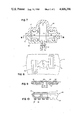
- FIG. 7 is a detail side partial cross-sectional view of a modification of the mold of FIG. 1;
- FIG. 8 is a detail top partial cross-sectional view of the mold of FIG. 7, taken along line 8--8 of FIG. 7;
- FIG. 9 is a detail side partial cross-sectional view of another modification of the mold of FIG. 1;
- FIG. 10 is a detail side partial cross-sectional view of a further modification of the mold of FIG. 1.
- the apparatus of the invention in general, includes a base 12 having mounted thereon a post 14 on which is mounted, for vertical sliding movement by power piston and cylinder 16, a horizontally extending arm 18.
- Chamber 20, hereinafter more fully described, is mounted on support member 19 which extends downwardly from the free end of arm 18 above a container 22 for holding molten metal.
- the rigid, self supporting, gas permeable, low temperature bonded, sand grain mold of the present invention is made by techniques and equipment well known in the art, of sand grains or equivalent particles and inorganic or organic thermal or chemical setting plastic or equivalent low temperature bonding material, with a minor percentage, usually about 5%, of the low temperature bonding material, by distributing the loose sand and bonding material mixture over metallic half patterns on a metal base plate which forms the parting plane, over which the mixture hardens into a rigid, self supporting mold half shell which is then removed from the metallic half patterns and base plate for use.
- the mold 30 is constructed of two such half shells, upper and lower, which are then adhesively secured together along horizontal mold parting plane 29 to provide a unitary, disposable, rigid, self supporting mold 30.
- Mold 30 has peripherally extending side surfaces 32 extending vertically between vertically spaced upper surface 31 and lower surface 33 which are generally parallel to mold parting plane 29.
- Surfaces 31 and 33 are irregular and have a rough outer surface since they were formed of generally uniform thickness on the irregular contour of the pattern.
- spring clips 36 and 37 For supporting mold 30 on chamber 20, a pair of opposed, upwardly extending metal spring clips 36 and 37 having inwardly and downwardly turned upper ends are mounted with their lower horizontal ends within parting plane 29.
- spring clips 36 and 37 are of a material which either melts or is destroyed at a temperature lower than that of the metal to be cast.
- said upper surface is formed at its outer edge, as by pressing it while still in plastic condition, to form a continuous peripheral horizontal flat sealing surface portion 38 suitable for sealing against chamber 20, as hereinafter more fully explained.
- a plurality of single part mold cavities are provided spaced between the upper and lower surfaces of mold 30, extending across mold parting plane 29, as shown in FIGS. 3 and 4, of which two are shown in FIG. 4. Multiple part cavities may also be so provided, as explained in more detail hereinafter. In commercial practice, the number of such mold cavities would generally fall between six and twenty, seventeen being shown in FIG. 3.
- Such single or multiple part mold cavities are distributed within the horizontal area within the periphery of mold 30, with a plurality thereof extending across the length and width of mold 30 between its upper and lower surface 31 and 33.
- Cavities 34 are horizontally spaced from one another generally in a horizontal plane and extend across parting plane 29.
- Each mold cavity such as is shown in connection with cavities 34, has an individual vertical gate passage 35, generally perpendicular to parting plane 29, extending from its lower side, with the lower open ends of such vertical gate passages 35 being spaced from one another both widthwise and lengthwise and terminating in a generally horizontal plane parallel to parting plane 29 at the lower surface 33 of mold 30.
- each of gate passages 35 must be relatively narrow in at least one dimension, at most not greater than 0.75 inch, and preferably not more than 0.5 inch, in order to function according to our invention.
- these narrow gate passages or portions thereof are vertical and of circular cross section, although other configurations may be used.
- chamber 20 provides the support for holding mold 30 against chamber 20 and for applying reduced pressure from vacuum pump 24 through a suitable valve 26 and hose 28 to its upper surface 31.
- chamber upper wall 44 is connected to the lower end of support 19 and is provided with an access port 58 to which vacuum hose 28 is connected for applying a reduced pressure to the interior of chamber 20 and to the upper surface 31 of mold 30 when desired.
- chamber 20 has a bottom opening defined by its downwardly extending peripheral outer wall 40 which extends downwardly from the outer periphery of its upper wall 44 to define the interior of chamber 20.
- outer wall 40 may be provided about its lower end with a horizontal sealing surface 42 for sealing against the horizontal upper sealing surface 38 of mold 30 around the periphery thereof and generally coextensive with the horizontal area of mold 30 containing the mold cavities, with a portion of the peripheral side surface 32 and bottom surface 33 of mold 30 extending downwardly beyond chamber 20.
- chamber 20 For supporting mold 30 against chamber 20 prior to the application of reduced pressure, chamber 20 is provided around its lower end with a peripheral abutment 41, the upper surface of which cooperates with the upper ends of spring clips 36 and 37 to support mold 30 with its sealing surface 38 in contact with sealing surface 42 of chamber 20.
- mold 30 In operation, with chamber 20 in raised position as shown in FIG. 1, mold 30 is manually or automatically positioned with its peripheral sealing surface 38 against sealing surface 42 of chamber 20 and with clips 36 and 37 engaging abutment 41.
- Power piston and cylinder 16 are then operated to move chamber 20 carrying mold 30 therebeneath downwardly toward container 22 to lower the lower surface 33 of mold 30 with the lower open ends of all of the vertical gate passages beneath the surface 60 of molten metal in container 22.
- Valve 26 is then operated to apply over enclosed upper surface 31 of mold 30, a reduced pressure, preferably only of about -1.0 to -3.0 psig (13.7 to 11.7 psia), through chamber port 58 to the interior of chamber 20 and the upper surface 31 of mold 30 within the periphery of sealing surface 38 and coextensive with the mold area containing the mold cavities.
- the reduced pressure applied to the upper surface 31 of mold 30 causes molten metal to rise into the gate passages and fill all the mold cavities simultaneously. The molten metal also destroys clips 36 and 37.
- the power piston and cylinder 16 are operated shortly after submergence, as soon as the mold cavities have been filled and molten metal extending across at least a portion of each of the gate passages has solidified, to raise chamber 20 and mold 30, whereupon a portion of molten metal remaining in the gate passages adjacent their lower ends below the solidified portion drains back into container 22, leaving unconnected metal parts, such as shown in FIG. 6, in mold 30. While chamber 20 and mold 30 are being raised, the reduced pressure provides the sole support of mold 30.
- valve 26 may be operated to disconnect the vacuum pump 24 and to release mold 30 so that a new mold can be substituted.
- the unconnected metal parts 62, with a short portion of gate passage metal 64 connected to them, as shown in FIG. 6, may then be separated from the decomposed mold 30 in the usual manner.
- clips 36 and 37 may be omitted and valve 26 may be operated initially to provide the sole force to hold mold 30 in operating position against chamber 20.
- FIGS. 7 through 10 are shown molds having multi-part cavities and multiple vertical gate passages.
- FIGS. 7 and 8 a portion of a multi-cavity mold, generally designated 65 and constructed as explained above, having, spaced between its upper surface 67 and its lower surface 69 and inwardly of its peripheral side surface 71, a plurality of multi-part mold cavities, of which one is shown in FIGS. 7 and 8.
- Each multi-part mold cavity includes two part cavities 73 and 75 having horizontal riser ingate passages 77 and 79, respectively, both connected to a central blind riser 78, which is in turn connected to a narrow vertical gate passage 80.
- the shape, quantity and size of the riser ingate passages 77 and 79 and of blind riser 78 may be varied to suit the particular casting shape and size.
- the transverse dimension of vertical gate passage 80 is about 0.25 to 0.50 inches in diameter, in accordance with the teachings of the methods of the present invention. More than one such vertical gate passage may be needed in certain circumstances.
- Molds of the type illustrated in FIGS. 7 and 8 are particularly useful when large parts, having part cavity dimensions in excess of 0.50 inches, for example, are to be molded, since otherwise there may be insufficient time available to completely solidify the molten metal in the mold part cavities before mold failure occurs, particularly with ferrous metals. Also, with metals which shrink upon solidification, the blind riser acts as a source of supply of molten metal during solidification of the metal in the part cavities.
- mold 65 is filled as described above and the mold removed from contact with the molten metal in the container as soon as molten metal has filled mold cavities 73 and 75 and blind riser 78 and has solidified in vertical gate passage 80.
- the metal in blind riser 78 remains molten for a sufficient period of time after the removal of mold 65 from contact with the molten metal in the container to continue to feed mold cavities 73 and 75 through their riser ingate passages 77 and 79 to compensate for shrinkage during solidification of the metal in the mold cavities 73 and 75.
- This arrangement allows the mold cycle time to be reduced so that premature mold failure is avoided.
- unconnected groups of metal parts including their connecting riser ingates and portions of the blind riser and the vertical gate, remain in the decomposed mold 65.
- FIG. 9 a multi-cavity mold 81 having, between its upper surface 82 and lower surface 83, a plurality of mold cavities 84, of which two are shown in FIG. 9, clustered around a central vertical gate passage 85 having narrow horizontal gate passage portions 86 according to the invention connecting the mold cavities 84 to vertical gate passage 85.
- This arrangement is satisfactory for casting parts having thicknesses of no more than about 0.5 inch, since solidification will immediately occur both in the mold cavities 84 and the narrow gate passage portions 86, with the molten metal draining from vertical gate passage 85 upon removal of mold 81 from contact with the underlying surface of molten metal to provide unconnected cast parts.
- FIG. 10 is shown a multi-cavity mold 90 having, between its upper surface 92 and its lower surface 94, a plurality of mold cavities 95, each having two vertical gate passages 97 and 98, for more rapid filling of the relatively large mold cavities 95 through narrow vertical gate passages in accordance with our invention in order to fill the mold cavities and remove the mold as soon as the metal in the vertical gate passages solidifies and before mold failure occurs.
- This type of mold is particularly useful when casting metals in which shrinkage compensation is not required, in molds having large part cavities which cannot be filled through a single narrow vertical gate passage before mold failure occurs.
Landscapes
- Engineering & Computer Science (AREA)
- Mechanical Engineering (AREA)
- Molds, Cores, And Manufacturing Methods Thereof (AREA)
Abstract
Description
Claims (13)
Priority Applications (1)
| Application Number | Priority Date | Filing Date | Title |
|---|---|---|---|
| US06/574,938 US4606396A (en) | 1978-10-02 | 1984-01-27 | Sand mold and apparatus for reduced pressure casting |
Applications Claiming Priority (2)
| Application Number | Priority Date | Filing Date | Title |
|---|---|---|---|
| US94762178A | 1978-10-02 | 1978-10-02 | |
| US06/574,938 US4606396A (en) | 1978-10-02 | 1984-01-27 | Sand mold and apparatus for reduced pressure casting |
Related Parent Applications (1)
| Application Number | Title | Priority Date | Filing Date |
|---|---|---|---|
| US06368671 Continuation | 1982-04-15 |
Publications (1)
| Publication Number | Publication Date |
|---|---|
| US4606396A true US4606396A (en) | 1986-08-19 |
Family
ID=27076538
Family Applications (1)
| Application Number | Title | Priority Date | Filing Date |
|---|---|---|---|
| US06/574,938 Expired - Lifetime US4606396A (en) | 1978-10-02 | 1984-01-27 | Sand mold and apparatus for reduced pressure casting |
Country Status (1)
| Country | Link |
|---|---|
| US (1) | US4606396A (en) |
Cited By (28)
| Publication number | Priority date | Publication date | Assignee | Title |
|---|---|---|---|---|
| US4858672A (en) * | 1988-05-25 | 1989-08-22 | General Motors Corporation | Countergravity casting apparatus and method |
| US4862945A (en) * | 1988-08-30 | 1989-09-05 | General Motors Corporation | Vacuum countergravity casting apparatus and method with backflow valve |
| US4862946A (en) * | 1988-11-23 | 1989-09-05 | General Motors Corporation | Vacuum countergravity casting apparatus and method |
| US4865113A (en) * | 1988-08-30 | 1989-09-12 | General Motors Corporation | Countergravity casting apparatus and process for casting thin-walled parts |
| US4874029A (en) * | 1988-05-09 | 1989-10-17 | General Motors Corporation | Countergravity casting process and apparatus using destructible patterns suspended in an inherently unstable mass of particulate mold material |
| US4922992A (en) * | 1988-12-27 | 1990-05-08 | General Motors Corporation | Melt-holding vessel and method of and apparatus for countergravity casting |
| US4957153A (en) * | 1989-05-02 | 1990-09-18 | General Motors Corporation | Countergravity casting apparatus and method |
| US4971131A (en) * | 1989-08-28 | 1990-11-20 | General Motors Corporation | Countergravity casting using particulate filled vacuum chambers |
| US4977946A (en) * | 1990-05-25 | 1990-12-18 | General Motors Corporation | Differential pressure, countergravity casting of individual charges of melt from a casting basin |
| US4977948A (en) * | 1988-07-15 | 1990-12-18 | General Motors Corporation | Countergravity casting apparatus and method using elastomeric sealing gasket and cooled vacuum chamber |
| US4989662A (en) * | 1990-02-27 | 1991-02-05 | General Motors Corporation | Differential pressure, countergravity casting of a melt with a fugative alloyant |
| US5029630A (en) * | 1990-07-03 | 1991-07-09 | General Motors Corporation | Differential pressure, countergravity casting apparatus using a vertically parted mold stack clamp mechanism |
| US5035277A (en) * | 1991-01-25 | 1991-07-30 | General Motors Corporation | Counter gravity casting apparatus |
| US5038846A (en) * | 1990-02-27 | 1991-08-13 | General Motors Corporation | Differential pressure, countergravity casting with alloyant reaction chamber |
| US5044420A (en) * | 1990-08-13 | 1991-09-03 | General Motors Corporation | Vacuum-assisted, countergravity casting apparatus and method |
| US5062466A (en) * | 1991-05-10 | 1991-11-05 | General Motors Corporation | Countergravity casting apparatus and method |
| US5062467A (en) * | 1991-05-10 | 1991-11-05 | General Motors Corporation | Vacuum countergravity casting apparatus and method |
| US5070930A (en) * | 1990-08-24 | 1991-12-10 | General Motors Corporation | Countergravity casting apparatus |
| US5088546A (en) * | 1991-05-10 | 1992-02-18 | General Motors Corporation | Vacuum-assisted counter gravity casting apparatus with valve to prevent flow of melt from mold |
| US5161604A (en) * | 1992-03-26 | 1992-11-10 | General Motors Corporation | Differential pressure, countergravity casting with alloyant reaction chamber |
| US5174356A (en) * | 1991-07-19 | 1992-12-29 | General Motors Corporation | Casting apparatus |
| WO1993011894A1 (en) * | 1991-12-09 | 1993-06-24 | Dansk Industri Syndikat A/S | Method and apparatus for upward-flow casting |
| US5320160A (en) * | 1988-07-31 | 1994-06-14 | Asahi Katantetsu Kabushiki Kaisha | Casting device, method for using the device, casting device of vehicle wheel, method for using the device, and vehicle wheel |
| US5348073A (en) * | 1992-04-02 | 1994-09-20 | Hitachi Metals, Ltd. | Method and apparatus for producing cast steel article |
| US5706880A (en) * | 1995-02-07 | 1998-01-13 | Hitachi Metals, Ltd. | Vacuum casting method and vacuum casting apparatus |
| US5724778A (en) | 1990-02-14 | 1998-03-10 | Steelcase Inc. | Furniture system |
| US5735334A (en) * | 1991-12-07 | 1998-04-07 | Alloy Technologies Limited | Casting of light metal alloys |
| US5865054A (en) | 1989-08-24 | 1999-02-02 | Aquaform Inc. | Apparatus and method for forming a tubular frame member |
Citations (11)
| Publication number | Priority date | Publication date | Assignee | Title |
|---|---|---|---|---|
| US1291390A (en) * | 1918-02-28 | 1919-01-14 | Thomas Broadbent | Casting apparatus. |
| US1591094A (en) * | 1925-01-14 | 1926-07-06 | Walter Kostelezky | Metal-molding machine |
| US1653232A (en) * | 1924-06-17 | 1927-12-20 | Smith Joseph Theodore | Molding device |
| US2476296A (en) * | 1945-08-08 | 1949-07-19 | Russell G Hardy | Metal casting apparatus |
| GB785837A (en) * | 1953-11-23 | 1957-11-06 | George Harrison | Method of and means for casting metals |
| US2908054A (en) * | 1958-03-03 | 1959-10-13 | Universal Castings Corp | Method of and means for casting metals under the influence of vacuum |
| US2923040A (en) * | 1956-07-16 | 1960-02-02 | Aluminum Co Of America | Casting process and machine |
| US3628598A (en) * | 1968-10-23 | 1971-12-21 | Modern Equipment Co | Casting molds |
| US3863706A (en) * | 1972-12-04 | 1975-02-04 | Hitchiner Manufacturing Co | Metal casting |
| US3900064A (en) * | 1972-12-04 | 1975-08-19 | Hitchiner Manufacturing Co | Metal casting |
| US4112997A (en) * | 1977-02-28 | 1978-09-12 | Hitchiner Manufacturing Co., Inc. | Metal casting |
-
1984
- 1984-01-27 US US06/574,938 patent/US4606396A/en not_active Expired - Lifetime
Patent Citations (11)
| Publication number | Priority date | Publication date | Assignee | Title |
|---|---|---|---|---|
| US1291390A (en) * | 1918-02-28 | 1919-01-14 | Thomas Broadbent | Casting apparatus. |
| US1653232A (en) * | 1924-06-17 | 1927-12-20 | Smith Joseph Theodore | Molding device |
| US1591094A (en) * | 1925-01-14 | 1926-07-06 | Walter Kostelezky | Metal-molding machine |
| US2476296A (en) * | 1945-08-08 | 1949-07-19 | Russell G Hardy | Metal casting apparatus |
| GB785837A (en) * | 1953-11-23 | 1957-11-06 | George Harrison | Method of and means for casting metals |
| US2923040A (en) * | 1956-07-16 | 1960-02-02 | Aluminum Co Of America | Casting process and machine |
| US2908054A (en) * | 1958-03-03 | 1959-10-13 | Universal Castings Corp | Method of and means for casting metals under the influence of vacuum |
| US3628598A (en) * | 1968-10-23 | 1971-12-21 | Modern Equipment Co | Casting molds |
| US3863706A (en) * | 1972-12-04 | 1975-02-04 | Hitchiner Manufacturing Co | Metal casting |
| US3900064A (en) * | 1972-12-04 | 1975-08-19 | Hitchiner Manufacturing Co | Metal casting |
| US4112997A (en) * | 1977-02-28 | 1978-09-12 | Hitchiner Manufacturing Co., Inc. | Metal casting |
Cited By (41)
| Publication number | Priority date | Publication date | Assignee | Title |
|---|---|---|---|---|
| EP0341486A3 (en) * | 1988-05-09 | 1990-12-12 | General Motors Corporation | Countergravity casting process and apparatus using destructible patterns suspended in an inherently unstable mass of particulate mold material |
| US4874029A (en) * | 1988-05-09 | 1989-10-17 | General Motors Corporation | Countergravity casting process and apparatus using destructible patterns suspended in an inherently unstable mass of particulate mold material |
| EP0341486A2 (en) * | 1988-05-09 | 1989-11-15 | General Motors Corporation | Countergravity casting process and apparatus using destructible patterns suspended in an inherently unstable mass of particulate mold material |
| EP0343372A3 (en) * | 1988-05-25 | 1990-12-27 | General Motors Corporation | Countergravity apparatus and method |
| EP0343372A2 (en) * | 1988-05-25 | 1989-11-29 | General Motors Corporation | Countergravity apparatus and method |
| US4858672A (en) * | 1988-05-25 | 1989-08-22 | General Motors Corporation | Countergravity casting apparatus and method |
| US4977948A (en) * | 1988-07-15 | 1990-12-18 | General Motors Corporation | Countergravity casting apparatus and method using elastomeric sealing gasket and cooled vacuum chamber |
| US5527101A (en) * | 1988-07-31 | 1996-06-18 | Asahi Katantetsu Kabushiki Kaisha | Casting device, method for using the device, casting device of vehicle wheel, method for using the device, and vehicle wheel |
| US5320160A (en) * | 1988-07-31 | 1994-06-14 | Asahi Katantetsu Kabushiki Kaisha | Casting device, method for using the device, casting device of vehicle wheel, method for using the device, and vehicle wheel |
| EP0356624A2 (en) * | 1988-08-30 | 1990-03-07 | General Motors Corporation | Vacuum countergravity casting apparatus and method with backflow valve |
| EP0356659A2 (en) * | 1988-08-30 | 1990-03-07 | General Motors Corporation | Countergravity casting apparatus and process for casting thinwalled parts |
| US4865113A (en) * | 1988-08-30 | 1989-09-12 | General Motors Corporation | Countergravity casting apparatus and process for casting thin-walled parts |
| EP0356624A3 (en) * | 1988-08-30 | 1991-04-10 | General Motors Corporation | Vacuum countergravity casting apparatus and method with backflow valve |
| EP0356659A3 (en) * | 1988-08-30 | 1991-04-10 | General Motors Corporation | Countergravity casting apparatus and process for casting thinwalled parts |
| US4862945A (en) * | 1988-08-30 | 1989-09-05 | General Motors Corporation | Vacuum countergravity casting apparatus and method with backflow valve |
| US4862946A (en) * | 1988-11-23 | 1989-09-05 | General Motors Corporation | Vacuum countergravity casting apparatus and method |
| EP0375955A2 (en) * | 1988-12-27 | 1990-07-04 | General Motors Corporation | Melt-holding vessel |
| EP0375955A3 (en) * | 1988-12-27 | 1990-10-03 | General Motors Corporation | Melt-holding vessel |
| US4922992A (en) * | 1988-12-27 | 1990-05-08 | General Motors Corporation | Melt-holding vessel and method of and apparatus for countergravity casting |
| US4957153A (en) * | 1989-05-02 | 1990-09-18 | General Motors Corporation | Countergravity casting apparatus and method |
| US5865054A (en) | 1989-08-24 | 1999-02-02 | Aquaform Inc. | Apparatus and method for forming a tubular frame member |
| US4971131A (en) * | 1989-08-28 | 1990-11-20 | General Motors Corporation | Countergravity casting using particulate filled vacuum chambers |
| EP0415091A2 (en) * | 1989-08-28 | 1991-03-06 | General Motors Corporation | Countergravity casting using particulate filled vacuum chambers |
| EP0415091A3 (en) * | 1989-08-28 | 1992-06-10 | General Motors Corporation | Countergravity casting using particulate filled vacuum chambers |
| US5724778A (en) | 1990-02-14 | 1998-03-10 | Steelcase Inc. | Furniture system |
| US5038846A (en) * | 1990-02-27 | 1991-08-13 | General Motors Corporation | Differential pressure, countergravity casting with alloyant reaction chamber |
| US4989662A (en) * | 1990-02-27 | 1991-02-05 | General Motors Corporation | Differential pressure, countergravity casting of a melt with a fugative alloyant |
| US4977946A (en) * | 1990-05-25 | 1990-12-18 | General Motors Corporation | Differential pressure, countergravity casting of individual charges of melt from a casting basin |
| US5029630A (en) * | 1990-07-03 | 1991-07-09 | General Motors Corporation | Differential pressure, countergravity casting apparatus using a vertically parted mold stack clamp mechanism |
| US5044420A (en) * | 1990-08-13 | 1991-09-03 | General Motors Corporation | Vacuum-assisted, countergravity casting apparatus and method |
| US5070930A (en) * | 1990-08-24 | 1991-12-10 | General Motors Corporation | Countergravity casting apparatus |
| US5035277A (en) * | 1991-01-25 | 1991-07-30 | General Motors Corporation | Counter gravity casting apparatus |
| US5088546A (en) * | 1991-05-10 | 1992-02-18 | General Motors Corporation | Vacuum-assisted counter gravity casting apparatus with valve to prevent flow of melt from mold |
| US5062467A (en) * | 1991-05-10 | 1991-11-05 | General Motors Corporation | Vacuum countergravity casting apparatus and method |
| US5062466A (en) * | 1991-05-10 | 1991-11-05 | General Motors Corporation | Countergravity casting apparatus and method |
| US5174356A (en) * | 1991-07-19 | 1992-12-29 | General Motors Corporation | Casting apparatus |
| US5735334A (en) * | 1991-12-07 | 1998-04-07 | Alloy Technologies Limited | Casting of light metal alloys |
| WO1993011894A1 (en) * | 1991-12-09 | 1993-06-24 | Dansk Industri Syndikat A/S | Method and apparatus for upward-flow casting |
| US5161604A (en) * | 1992-03-26 | 1992-11-10 | General Motors Corporation | Differential pressure, countergravity casting with alloyant reaction chamber |
| US5348073A (en) * | 1992-04-02 | 1994-09-20 | Hitachi Metals, Ltd. | Method and apparatus for producing cast steel article |
| US5706880A (en) * | 1995-02-07 | 1998-01-13 | Hitachi Metals, Ltd. | Vacuum casting method and vacuum casting apparatus |
Similar Documents
| Publication | Publication Date | Title |
|---|---|---|
| US4340108A (en) | Method of casting metal in sand mold using reduced pressure | |
| US4606396A (en) | Sand mold and apparatus for reduced pressure casting | |
| CA1055675A (en) | Method and sealing element for sealingly connecting a mould to a metal supply pipe of a low-pressure casting apparatus | |
| JP2905939B2 (en) | Molds and casting and cooling zones in continuous casting plants | |
| US4993473A (en) | Differential pressure, countergravity casting using mold ingate chills | |
| CA1146717A (en) | Metal casting | |
| US4862945A (en) | Vacuum countergravity casting apparatus and method with backflow valve | |
| FI92807B (en) | Lost-foam method for casting metal articles under controlled pressure | |
| US5355933A (en) | Method of squeeze casting metal articles using melt-out metal core | |
| US2561062A (en) | Pressure casting apparatus | |
| JPH048136B2 (en) | ||
| US5088546A (en) | Vacuum-assisted counter gravity casting apparatus with valve to prevent flow of melt from mold | |
| JP2560356B2 (en) | Vacuum suction precision casting method | |
| US3760864A (en) | Method of casting in thin-walled molds | |
| JPH08318361A (en) | Differential pressure casting method and differential pressure casting mold used to this method | |
| KR100193236B1 (en) | Manufacturing Equipment Of Magnesium Castings | |
| JPH0241751A (en) | Device for casting wheel for vehicle | |
| JPS5884662A (en) | Pressure casting method and equipment | |
| JP2585842Y2 (en) | Casting mold equipment | |
| JPH0741400B2 (en) | Suction casting method in green casting | |
| JPS631145B2 (en) | ||
| JPH0694063B2 (en) | Casting method and mold for fiber-reinforced metal body | |
| JPS613647A (en) | Mold device | |
| JPS5850168A (en) | Prevention for clogging of sprue | |
| JPH0635042B2 (en) | Casting method for fiber-reinforced metal body |
Legal Events
| Date | Code | Title | Description |
|---|---|---|---|
| CC | Certificate of correction | ||
| AS | Assignment |
Owner name: GENERAL MOTORS CORPORATION, 3044 WEST GRAND BLVD., Free format text: ASSIGNMENT OF ASSIGNORS INTEREST.;ASSIGNOR:HITCHINER MANUFACTURING, CO., INC.;REEL/FRAME:004702/0333 Effective date: 19870401 Owner name: GENERAL MOTORS CORPORATION, A CORP. OF DE.,MICHI Free format text: ASSIGNMENT OF ASSIGNORS INTEREST;ASSIGNOR:HITCHINER MANUFACTURING, CO., INC.;REEL/FRAME:004702/0333 Effective date: 19870401 |
|
| FPAY | Fee payment |
Year of fee payment: 4 |
|
| FEPP | Fee payment procedure |
Free format text: PETITION RELATED TO MAINTENANCE FEES FILED (ORIGINAL EVENT CODE: PMFP); ENTITY STATUS OF PATENT OWNER: LARGE ENTITY |
|
| FEPP | Fee payment procedure |
Free format text: PETITION RELATED TO MAINTENANCE FEES GRANTED (ORIGINAL EVENT CODE: PMFG); ENTITY STATUS OF PATENT OWNER: LARGE ENTITY |
|
| REMI | Maintenance fee reminder mailed | ||
| FPAY | Fee payment |
Year of fee payment: 8 |
|
| SULP | Surcharge for late payment | ||
| FP | Lapsed due to failure to pay maintenance fee |
Effective date: 19940824 |
|
| STCF | Information on status: patent grant |
Free format text: PATENTED CASE |
|
| DP | Notification of acceptance of delayed payment of maintenance fee | ||
| FPAY | Fee payment |
Year of fee payment: 12 |