US4583936A - Frequency modulated burner system - Google Patents
Frequency modulated burner system Download PDFInfo
- Publication number
- US4583936A US4583936A US06/507,539 US50753983A US4583936A US 4583936 A US4583936 A US 4583936A US 50753983 A US50753983 A US 50753983A US 4583936 A US4583936 A US 4583936A
- Authority
- US
- United States
- Prior art keywords
- burner
- air
- fuel
- rate
- combustion
- Prior art date
- Legal status (The legal status is an assumption and is not a legal conclusion. Google has not performed a legal analysis and makes no representation as to the accuracy of the status listed.)
- Expired - Fee Related
Links
- 238000002485 combustion reaction Methods 0.000 claims abstract description 120
- 239000000446 fuel Substances 0.000 claims abstract description 92
- 239000000203 mixture Substances 0.000 claims abstract description 11
- 230000008859 change Effects 0.000 claims description 18
- 238000000034 method Methods 0.000 claims description 10
- 239000007789 gas Substances 0.000 claims description 7
- 238000004891 communication Methods 0.000 claims description 3
- 239000011819 refractory material Substances 0.000 claims 2
- 239000012530 fluid Substances 0.000 claims 1
- 230000001590 oxidative effect Effects 0.000 abstract description 2
- 239000003570 air Substances 0.000 description 72
- 238000010438 heat treatment Methods 0.000 description 7
- VNWKTOKETHGBQD-UHFFFAOYSA-N methane Chemical compound C VNWKTOKETHGBQD-UHFFFAOYSA-N 0.000 description 6
- 230000008901 benefit Effects 0.000 description 5
- 239000012080 ambient air Substances 0.000 description 3
- 230000003247 decreasing effect Effects 0.000 description 3
- 239000003345 natural gas Substances 0.000 description 3
- MWUXSHHQAYIFBG-UHFFFAOYSA-N nitrogen oxide Inorganic materials O=[N] MWUXSHHQAYIFBG-UHFFFAOYSA-N 0.000 description 3
- IJGRMHOSHXDMSA-UHFFFAOYSA-N Atomic nitrogen Chemical compound N#N IJGRMHOSHXDMSA-UHFFFAOYSA-N 0.000 description 2
- 230000004075 alteration Effects 0.000 description 2
- XAGFODPZIPBFFR-UHFFFAOYSA-N aluminium Chemical compound [Al] XAGFODPZIPBFFR-UHFFFAOYSA-N 0.000 description 2
- 229910052782 aluminium Inorganic materials 0.000 description 2
- 230000015572 biosynthetic process Effects 0.000 description 2
- 239000006227 byproduct Substances 0.000 description 2
- 238000010304 firing Methods 0.000 description 2
- 230000006870 function Effects 0.000 description 2
- 239000000463 material Substances 0.000 description 2
- 238000012986 modification Methods 0.000 description 2
- 230000004048 modification Effects 0.000 description 2
- 238000012544 monitoring process Methods 0.000 description 2
- RYGMFSIKBFXOCR-UHFFFAOYSA-N Copper Chemical compound [Cu] RYGMFSIKBFXOCR-UHFFFAOYSA-N 0.000 description 1
- 239000011398 Portland cement Substances 0.000 description 1
- 229910000831 Steel Inorganic materials 0.000 description 1
- 238000013459 approach Methods 0.000 description 1
- QVGXLLKOCUKJST-UHFFFAOYSA-N atomic oxygen Chemical compound [O] QVGXLLKOCUKJST-UHFFFAOYSA-N 0.000 description 1
- 238000006243 chemical reaction Methods 0.000 description 1
- 239000004927 clay Substances 0.000 description 1
- 238000009841 combustion method Methods 0.000 description 1
- 229910052802 copper Inorganic materials 0.000 description 1
- 239000010949 copper Substances 0.000 description 1
- 238000005336 cracking Methods 0.000 description 1
- 230000007423 decrease Effects 0.000 description 1
- 238000005242 forging Methods 0.000 description 1
- 239000000295 fuel oil Substances 0.000 description 1
- 238000009434 installation Methods 0.000 description 1
- 238000004519 manufacturing process Methods 0.000 description 1
- 238000002844 melting Methods 0.000 description 1
- 230000008018 melting Effects 0.000 description 1
- 229910052757 nitrogen Inorganic materials 0.000 description 1
- 239000003921 oil Substances 0.000 description 1
- 230000003647 oxidation Effects 0.000 description 1
- 238000007254 oxidation reaction Methods 0.000 description 1
- 239000001301 oxygen Substances 0.000 description 1
- 229910052760 oxygen Inorganic materials 0.000 description 1
- 239000000047 product Substances 0.000 description 1
- 230000002035 prolonged effect Effects 0.000 description 1
- 239000010959 steel Substances 0.000 description 1
- 238000012546 transfer Methods 0.000 description 1
Images


Classifications
-
- F—MECHANICAL ENGINEERING; LIGHTING; HEATING; WEAPONS; BLASTING
- F23—COMBUSTION APPARATUS; COMBUSTION PROCESSES
- F23N—REGULATING OR CONTROLLING COMBUSTION
- F23N1/00—Regulating fuel supply
- F23N1/02—Regulating fuel supply conjointly with air supply
- F23N1/022—Regulating fuel supply conjointly with air supply using electronic means
-
- F—MECHANICAL ENGINEERING; LIGHTING; HEATING; WEAPONS; BLASTING
- F23—COMBUSTION APPARATUS; COMBUSTION PROCESSES
- F23C—METHODS OR APPARATUS FOR COMBUSTION USING FLUID FUEL OR SOLID FUEL SUSPENDED IN A CARRIER GAS OR AIR
- F23C6/00—Combustion apparatus characterised by the combination of two or more combustion chambers or combustion zones, e.g. for staged combustion
- F23C6/04—Combustion apparatus characterised by the combination of two or more combustion chambers or combustion zones, e.g. for staged combustion in series connection
- F23C6/045—Combustion apparatus characterised by the combination of two or more combustion chambers or combustion zones, e.g. for staged combustion in series connection with staged combustion in a single enclosure
-
- F—MECHANICAL ENGINEERING; LIGHTING; HEATING; WEAPONS; BLASTING
- F23—COMBUSTION APPARATUS; COMBUSTION PROCESSES
- F23D—BURNERS
- F23D14/00—Burners for combustion of a gas, e.g. of a gas stored under pressure as a liquid
- F23D14/46—Details, e.g. noise reduction means
- F23D14/62—Mixing devices; Mixing tubes
- F23D14/64—Mixing devices; Mixing tubes with injectors
-
- F—MECHANICAL ENGINEERING; LIGHTING; HEATING; WEAPONS; BLASTING
- F23—COMBUSTION APPARATUS; COMBUSTION PROCESSES
- F23N—REGULATING OR CONTROLLING COMBUSTION
- F23N2221/00—Pretreatment or prehandling
- F23N2221/08—Preheating the air
-
- F—MECHANICAL ENGINEERING; LIGHTING; HEATING; WEAPONS; BLASTING
- F23—COMBUSTION APPARATUS; COMBUSTION PROCESSES
- F23N—REGULATING OR CONTROLLING COMBUSTION
- F23N2223/00—Signal processing; Details thereof
- F23N2223/08—Microprocessor; Microcomputer
-
- F—MECHANICAL ENGINEERING; LIGHTING; HEATING; WEAPONS; BLASTING
- F23—COMBUSTION APPARATUS; COMBUSTION PROCESSES
- F23N—REGULATING OR CONTROLLING COMBUSTION
- F23N2223/00—Signal processing; Details thereof
- F23N2223/36—PID signal processing
-
- F—MECHANICAL ENGINEERING; LIGHTING; HEATING; WEAPONS; BLASTING
- F23—COMBUSTION APPARATUS; COMBUSTION PROCESSES
- F23N—REGULATING OR CONTROLLING COMBUSTION
- F23N2225/00—Measuring
- F23N2225/04—Measuring pressure
-
- F—MECHANICAL ENGINEERING; LIGHTING; HEATING; WEAPONS; BLASTING
- F23—COMBUSTION APPARATUS; COMBUSTION PROCESSES
- F23N—REGULATING OR CONTROLLING COMBUSTION
- F23N2225/00—Measuring
- F23N2225/08—Measuring temperature
-
- F—MECHANICAL ENGINEERING; LIGHTING; HEATING; WEAPONS; BLASTING
- F23—COMBUSTION APPARATUS; COMBUSTION PROCESSES
- F23N—REGULATING OR CONTROLLING COMBUSTION
- F23N2225/00—Measuring
- F23N2225/08—Measuring temperature
- F23N2225/16—Measuring temperature burner temperature
-
- F—MECHANICAL ENGINEERING; LIGHTING; HEATING; WEAPONS; BLASTING
- F23—COMBUSTION APPARATUS; COMBUSTION PROCESSES
- F23N—REGULATING OR CONTROLLING COMBUSTION
- F23N2227/00—Ignition or checking
- F23N2227/10—Sequential burner running
-
- F—MECHANICAL ENGINEERING; LIGHTING; HEATING; WEAPONS; BLASTING
- F23—COMBUSTION APPARATUS; COMBUSTION PROCESSES
- F23N—REGULATING OR CONTROLLING COMBUSTION
- F23N5/00—Systems for controlling combustion
- F23N5/18—Systems for controlling combustion using detectors sensitive to rate of flow of air or fuel
Definitions
- the present invention relates to the art of combustion methods and apparatus.
- the invention finds particular application in conjunction with furnaces and will be described with reference thereto. It is to be appreciated, however, that the invention is equally applicable to many combustion installations including boilers, kilns, and other heating apparatus.
- industrial furnaces have included a combustion chamber in which a plurality of burners were located.
- Amplitude modulated control systems were utilized to control the temperature within the combustion chamber. Specifically, a controller would sense the temperature within the combustion chamber, compare the sensed temperature with a selected temperature, and control the amount of fuel and air supplied to the burners. In this manner, the burners combusted fuel at a varied rate to maintain or reach a selected temperature.
- One of the problems with the amplitude modulated furnace systems is that they are relatively fuel inefficient. Physical attributes and limitations of the prior art burners caused them to obtain a peak combustion efficiency at a specific or small range of air-to-fuel ratios. When the burners combust fuel either more or less rapidly than the peak efficiency air/fuel ratio, they operate with relatively less fuel efficiency. Further, it is difficult to maintain a stoichiometrically balanced air/fuel ratio over a wide range of air and fuel supply rates.
- Another problem with the amplitude modulated burner systems has been that at reduced heats, they have relatively low conductive heat transfer characteristics. Particularly, the heated gases have less momentum at lower temperature settings, i.e., at lower combustion rates. Further, the burners are frequently unable to maintain stable flames over a wide range of heating rates.
- a frequency modulated control system with two-stage burners for combustion apparatus is provided to overcome the above-referenced problems and others, yet reliably maintain an accurate temperature control with high fuel efficiency.
- a combustion apparatus including a combustion chamber, at least one burner, and a frequency modulated burner control system.
- the frequency modulated burner control system cyclically actuates the burner at a preselected, fixed combustion rate and deactuates the burner for selectively adjustable portions of each cycle.
- the control system controls the combustion chamber temperature by controlling the duty cycle of the burner, i.e., the burner actuation to deactuation ratio in each cycle.
- a method of combusting fuel Fuel and air are supplied to a burner.
- the burner is cyclically actuated to combust fuel at a preselected rate and then deactuated.
- a duty cycle at which the burner is actuated at the fixed combustion rate is selectively varied to vary the amount of heat produced.
- the combustion chamber includes a plurality of burners.
- a synchronization means is provided for synchronizing the actuation of the burners in a staged manner.
- each burner includes a first stage combustion area for partially combusting a fuel rich air/fuel mixture, and a second stage combustion area downstream from the first stage combustion area for completing combustion.
- an automatic air/fuel ratio adjustment is advantageously provided.
- the air/fuel ratio adjustment is effected by an override means for periodically overriding the burner control means to cause the burner to be actuated for a calibration duration without regard to the combustion chamber temperature.
- air flow measuring means measures the air flow to the burner, and air flow comparing means compares the measured air supply rate with an optimal air supply rate. Under the control of the air flow comparing means, the rate at which air is supplied is selectively adjusted.
- a primary advantage of the present invention is the conversion of fuel into heat energy with a high degree of efficiency over a wide range of thermal input rates.
- Another advantage of the subject new frequency modulated combustion system resides in the provision of a wide range of selectable thermal inputs, i.e., a large turndown ratio.
- Still another advantage of the invention is that the burners maintain a stable flame over a wide range of thermal input rates.
- Still further advantages of the invention include providing a higher burn momentum, achieving temperatures greater than 1200° F. in the combustion chamber, and reducing the formation of nitrogen oxides.
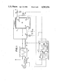
- FIG. 1 is a diagrammatic illustration of a combustion apparatus constructed in accordance with the present invention
- FIG. 2 is an end view in partial section from a combustion chamber of a burner formed in accordance with the invention
- FIG. 3 is a cross-sectional view taken along lines 3--3 of FIG. 2;
- FIG. 4 is an enlarged, cross-sectional view of a first stage combustion area taken along lines 4--4 of FIG. 3;
- FIG. 5 is an enlarged, cross-sectional view of a sight passage in the burner of FIG. 2;
- FIG. 6 is a logic flow chart for programming an air/fuel ratio logic control circuit or microcomputer of FIG. 1;
- FIG. 7 is a logic flow chart for programming a temperature control logic circuit or microprocessor of FIG. 1;
- FIGS. 8A, 8B, and 8C illustrate typical burner cycle relationships for a two-burner system
- FIG. 9 is a diagrammatic illustration of a hard wired embodiment for implementing the logic of FIGS. 6 and 7.
- FIG. 1 shows a combustion apparatus A, such as a furnace, which is suitably constructed to hold articles or otherwise define a region to be heated.
- a plurality of burners B are mounted in the combustion apparatus for oxidizing natural gas or other fuel to heat the combustion chamber, hence the articles to be heated.
- a frequency modulated burner control system C controls the temperature by controlling the duty cycle of the burners. That is, the burners are cyclically actuated at a fixed burner rate and deactuated. The actuation to deactuation ratio of each cycle is controlled to vary the thermal input to the combustion apparatus correspondingly. Further, the control means automatically adjusts and controls the air/fuel ratio to maintain the combustion at optimum efficiency.
- the frequency modulated combustion system finds application in many environments including hardening furnaces, aluminum heat treating, aluminum melting, forging, batch coil heating, ingot heating, slab heating, structural clay product burning, portland cement manufacturing, steel heat treating, copper slab heating, oil pipe heating treating, and the like.
- the combustion apparatus A includes a combustion chamber 10 in which articles to be heated are positionable.
- An air supply means supplies ambient air at a selectable rate to the burners for combustion.
- This air supply means includes a blower 12 which pumps ambient air through a flow meter 14 and a heat exchanger 16. Preheated air from the heat exchanger is passed at a selectable rate by an air flow rate adjusting means or valve 18.
- Air supply solenoid valves 20, 22 each selectively block and permit the flow of air at the selected air flow rate to an associated burner during combustion periods. That is, the air supply solenoid valves alternately enable the burner to receive air at the selected air flow rate and to receive substantially no air flow.
- fuel supply solenoid valves 24, 26 selectively enable and disable the flow of natural gas or other fuel to the burners.
- two burners B are illustrated, it is to be appreciated that the invention is applicable to single burner systems, as well as to systems having more than two burners.
- the burner B includes a fuel receiving portion 30 for receiving natural gas or other fuel at inlet 30a from the associated solenoid fuel valve, and an air receiving portion 32 for receiving preheated combustion air at inlet 32a from the associated air control solenoid valve.
- a fuel tube 34 communicating with portion 32 and an air tube 36 disposed concentrically around tube 34 in communication with portion 36 channel fuel and air to a mixing chamber or area 38.
- the fuel and air tubes and the fuel and air supply means are configured and adjusted to provide a fuel rich mixture to the mixing area 38.
- a second tube for carrying an alternate fuel such as fuel oil may be disposed concentric with fuel tube 34 to inject such alternate fuel into the mixing chamber 38.
- a pair of pilot gas jets from pilot means 40, 42 provide a continuous ignition means adjacent a downstream end of the mixing area.
- the fuel rich mixture is ignited by the pilots and partially combusted in a first stage combustion area 44.
- the first stage combustion area is defined by a refractory member of material 46 which includes a cylindrical passage therethrough.
- the refractory member or material terminates at a combustion chamber face 48.
- a plurality of air passages 50, 52, 54, and 56 communicate between air receiving portion 32 and the combustion chamber. These passages extend roughly parallel to the flow direction of partially combusted fuel in the first stage combustion area 44 to supply additional preheated air to the second stage combustion area.
- a sight passage 58 penetrates area 44 from externally of the burner so that an operator can view the first stage combustion area for the presence of flames or other evidence of combustion.
- the two-stage combustion provides jet-like combustion with high momentum, i.e., momentum in excess of conventional burners.
- the high momentum injects heat more efficiently into the combustion chamber.
- the high momentum causes turbulence rather than laminar flow, and such turbulence injects and mixes the heat efficiently into the combustion chamber.
- the two-stage combustion releases the heat in two stages. This prolonged burning of the fuel releases the same number of calories of heat but without attaining as high a combustion temperature.
- the lower combustion temperature is advantageous in that it inhibits the fuel from cracking and altering its combustion properties. Still further, the lower combustion temperature reduces the formation of nitrogen oxidation by-products (NO x ).
- the controller C includes an air-to-fuel ratio adjustment means for adjusting the ratio of the air and fuel supplied to the burner.
- the air/fuel ratio adjustment means includes a microprocessor or logic means 60 which computes the appropriate rate of air flow and a proportional, integral, differential (PID) algorithm means 62 for converting the selected air flow rate into an appropriate analog control signal for the control valve 18.
- PID proportional, integral, differential
- the air/fuel ratio adjustment microprocessor 60 is programmed in accordance with the programming flow chart of FIG. 6.
- the air/fuel ratio adjustment processor and program include a step or means 64 for monitoring the burners to determine the beginning of a burner cycle.
- Calibration duration timing means or step 66 times a calibration duration.
- the calibration duration timing means or step 66 actuates an override step or means 68 for forcing the burners to the full on condition for the calibration duration.
- An air flow comparing means 70 compares the air flow measured by the air flow meter 14 with flow rates from a preprogrammed history memory. From the preprogrammed history memory, the comparing means retrieves a preselected flow rate for the present conditions.
- the air flow rate comparing means compares the measured air supply rate and the historical or theoretically optimal air supply rate to determine the deviation therebetween.
- a valve adjustment means or step 72 converts this air flow deviation into a control signal for the air flow rate adjusting valve 18.
- a means or step 74 checks the calibration duration timer 66 to determine whether the calibration duration has expired. If the calibration duration has not expired, steps 68 through 72 are repeated; however, if the calibration duration has expired, a step or means 76 deactivates the air/fuel ratio adjustment means until the next calibration cycle, i.e., once every quarter hour.
- the controller C further includes a frequency modulated (FM) burner control system for cyclically actuating the burner at the selected, fixed burn rate and for deactuating the burner, i.e., varying the duty cycle.
- the FM burner control means includes a proportional, integral, differential (PID) algorithm means 80, and a frequency modulated burner control logic or microprocessor means 82.
- the proportional, integral, differential algorithm means 80 monitors the temperature of the combustion chamber and provides output signals which are proportional to the temperature, vary with the integral of the temperature, and vary with the derivative of the combustion chamber temperature. That is, the PID algorithm means provides the temperature, the amount of heat energy released into the combustion chamber, and an indication of the rate of change of the temperature.
- the frequency modulated burner control logic means 82 converts this information into appropriate control signals for the fuel and air solenoid valves 20, 22, 24, and 26.
- the logic means 82 comprises a microprocessor which is programmed in accordance with the programming flow chart of FIG. 7.
- the frequency modulated burner control processor and the program include an error means or step 84 for determining a deviation between the sensed combustion chamber temperature and a selected or set point temperature.
- a temperature history step or means 86 computes and stores the temperature deviation as a function of time.
- a rate of change means or step 88 determines the rate of change of the temperature deviation from the temperature data stored in the temperature history means 86. For a fixed set point temperature, the change in temperature deviation is equivalent to the change of the sensed temperature.
- a duty cycle means or step 90 determines the appropriate on/off ratio of the burners from the temperature deviation and the rate of change history.
- the duty cycle means may comprise a two-dimensional look-up table which is addressed by the magnitude of the temperature deviation and the rate of change of the temperature deviation.
- Each memory cell of the two-dimensional history memory is preprogrammed with appropriate on/off ratio to zero the temperature deviation without substantial overshoot.
- various mathematical algorithms may be implemented to project the convergence of the sensed and set point temperatures.
- a cycle time means or step 92 converts the on/off ratio to time. That is, the cycle timer means calculates how long the burner is to be actuated in each cycle.
- a synchronizing step or means 94 synchronizes actuation of the burners.
- each cycle extends for a duration or cycle time t.
- the burners are turned on and off once per cycle unless the system is in a maximum heat output mode, i.e., continuously actuated.
- each cycle time is in the range of 10 seconds to 2 minutes.
- longer and shorter cycle times are appropriate for some applications. Shorter cycles tend to maintain the combustion chamber temperature constant with greater precision. Longer cycles provide a wider range of duty cycles, i.e., turndown ratios.
- the cycle time is of sufficient duration to provide a selected range of turndown ratios. In the preferred embodiment, the turndown ratio is at least 10:1 and preferably about 100:1.
- the maximum turndown rate actuates the burner for a duration which is at least as long as its ignition time. Because the burners tend to be less efficient during ignition than during full combustion, higher efficiency is achieved when the burner is actuated for a duration which is long compared to the ignition time.
- the burners of the preferred embodiment achieve full, steady state combustion in an ignition time of approximately 0.3 seconds. Thus, with the preferred burners, a cycle time of 30 seconds can provide a 100:1 turndown ratio.
- FIGS. 8A, 8B, and 8C illustrate a preferred synchronization schedule for a two-burner system.
- the maximum heat input condition is illustrated in FIG. 8A.
- the first and second burners are each operated for the full cycle time t.
- the synchronization means turns each burner on for two-thirds of the cycle period, i.e., a 1.5:1 turndown ratio.
- the first burner is ignited from the beginning of each cycle to two-thirds of the cycle, i.e., 2t/3.
- the second burner is ignited for the last two-thirds of the cycle, i.e., from t/3 to the end of the cycle. This provides an overlap of one-third of the cycle time in the middle of each cycle in which both burners are ignited.
- FIG. 8C illustrates the ignition of each burner for a 4:1 turndown ratio.
- the first burner is ignited from the beginning of each cycle until a quarter of the way into it, i.e., t/4, and the second burner is ignited for the last quarter of the cycle, i.e., from 3t/4 to the end of the cycle.
- t/4 quarter of the way into it
- the second burner is ignited for the last quarter of the cycle, i.e., from 3t/4 to the end of the cycle.
- the first and second burners may be operated 180° out of phase such that the first burner ignites at the beginning of a cycle and the second burner ignites at the midpoint of the cycle.
- the burners may be divided into two groups or banks and operated as described above. Alternately, with n burners, the burners may be operated 360°/n out of phase. Use of these various alternatives does not, however, in any way depart from the overall intent or scope of invention.
- a system clock 100 provides timing pulses to coordinate circuit elements and to provide timing functions.
- a calibration periodicity timer 102 periodically determines that a calibration cycle is to occur.
- a burner cycle monitoring means 64' monitors for the beginning of each burner cycle.
- a calibration duration timer 66' is enabled by the calibration periodicity timer 102 and start cycle sensor to have an override means 68' cause air and fuel solenoids 20', 22', 24', and 26' to be held open for the calibration duration.
- a temperature sensing means 28', an atmospheric pressure sensing means 104a, and other air condition sensing means 104z sense atmospheric pressure, ambient air temperature, humidity, or other such conditions which reflect upon the oxygen content of the air to be burned.
- sensors may also be provided for sensing variations in the supplied fuel or for sensing variations in combustion by-products.
- An air flow history memory 106 is addressed with these conditions to retrieve or calculate a selected air flow rate for the sensed conditions.
- An air flow meter or sensing means 14' senses the air flow into the combustion chamber.
- An air flow comparing means 70' compares the selected air flow rate for the sensed conditions with the sensed air flow rate and determines a deviation in the air flow rate.
- An air flow valve adjusting means 72' adjusts an air flow rate controlling valve 18' in accordance with the air flow rate deviation to bring the actual air flow into accord with the selected air flow.
- the frequency modulated burner control means includes a set point temperature means 110 on which a selected temperature is set.
- An error means 84' compares the sensed and set point temperatures to determine a deviation therebetween.
- a temperature history memory means 86' stores a record of the temperature deviation at each of a plurality of measuring times.
- a temperature change rate means 88' determines the rate of change of the temperature deviation from the information stored in the temperature history memory means 86'.
- a two-dimensional duty cycle memory means 90' is indexed by the present temperature change rate and by the present temperature deviation. From these two inputs, a unique memory cell is addressed which indicates a preprogrammed appropriate duty cycle that is calculated to cause the sensed temperature to converge upon the set point temperature.
- a cycle time means 92' determines the duration which each burner must be actuated within each cycle to accomplish the selected duty cycle.
- An on/off valve interface means 112 turns the fuel and air control valves 20', 22', 24' and 26' on and off under the control of the cycle time means and a synchronization means 94'.
- the synchronization means subtracts the on time from the cycle time to determine the actuation time for the second burner, i.e., the burner which is actuated from the variable on time to the end of the cycle.
- the heat demand during start-up is high and all burners are fired at full capacity.
- the demand decreases and the burners are operated at a turndown condition, i.e., a lesser portion of each cycle.
- the heat demand is also decreased and the burners are operated at a turndown condition.
- the heat may be varied during the treatment of articles or workpieces in the furnace A. When the heat is increased, the duty cycle is correspondingly increased, and when the heat is decreased, the duty cycle is correspondingly decreased.
Landscapes
- Engineering & Computer Science (AREA)
- Chemical & Material Sciences (AREA)
- Combustion & Propulsion (AREA)
- Mechanical Engineering (AREA)
- General Engineering & Computer Science (AREA)
- Feeding And Controlling Fuel (AREA)
Abstract
Description
Claims (19)
Priority Applications (1)
| Application Number | Priority Date | Filing Date | Title |
|---|---|---|---|
| US06/507,539 US4583936A (en) | 1983-06-24 | 1983-06-24 | Frequency modulated burner system |
Applications Claiming Priority (1)
| Application Number | Priority Date | Filing Date | Title |
|---|---|---|---|
| US06/507,539 US4583936A (en) | 1983-06-24 | 1983-06-24 | Frequency modulated burner system |
Publications (1)
| Publication Number | Publication Date |
|---|---|
| US4583936A true US4583936A (en) | 1986-04-22 |
Family
ID=24019034
Family Applications (1)
| Application Number | Title | Priority Date | Filing Date |
|---|---|---|---|
| US06/507,539 Expired - Fee Related US4583936A (en) | 1983-06-24 | 1983-06-24 | Frequency modulated burner system |
Country Status (1)
| Country | Link |
|---|---|
| US (1) | US4583936A (en) |
Cited By (56)
| Publication number | Priority date | Publication date | Assignee | Title |
|---|---|---|---|---|
| US4768947A (en) * | 1986-10-16 | 1988-09-06 | Rinnai Corporation | Burner apparatus |
| US4834644A (en) * | 1987-02-24 | 1989-05-30 | Snow Corporation | Premix oven pulsing control system |
| EP0342347A2 (en) * | 1988-04-16 | 1989-11-23 | Conel Ag | Method for reducing the effect of deregulating factors for ventilator burners and ventilator burners |
| EP0356764A1 (en) * | 1988-09-01 | 1990-03-07 | Lve Verfahrenselektronik Gmbh | Method and arrangement for regulating a pulse-controlled burner in a heat-producing installation |
| US4994959A (en) * | 1987-12-03 | 1991-02-19 | British Gas Plc | Fuel burner apparatus and a method of control |
| US5248083A (en) * | 1992-11-09 | 1993-09-28 | Honeywell Inc. | Adaptive furnace control using analog temperature sensing |
| WO1994009315A1 (en) * | 1992-10-16 | 1994-04-28 | Gas Research Institute, Inc. | STAGED AIR, RECIRCULATING FLUE GAS LOW NOx BURNER |
| US5307990A (en) * | 1992-11-09 | 1994-05-03 | Honeywell, Inc. | Adaptive forced warm air furnace using analog temperature and pressure sensors |
| US5361710A (en) * | 1993-10-07 | 1994-11-08 | The United States Of America As Represented By The Secretary Of The Navy | Method and apparatus for the active control of a compact waste incinerator |
| US5428951A (en) * | 1993-08-16 | 1995-07-04 | Wilson; Kenneth | Method and apparatus for active control of combustion devices |
| US5445517A (en) * | 1992-10-14 | 1995-08-29 | Matsushita Electric Industrial Co., Ltd. | Adaptive noise silencing system of combustion apparatus |
| US5522721A (en) * | 1993-10-29 | 1996-06-04 | L'air Liquide, Societe Anonyme Pour L'etude Et L'exploitation Des Procedes Georges Claude | Process for combustion in an industrial furnace |
| EP0733187A1 (en) * | 1993-12-08 | 1996-09-25 | Maxon Corporation | Oxygen-fuel burner with integral staged oxygen supply |
| US5581471A (en) * | 1994-04-08 | 1996-12-03 | Mceachern; Alexander | Method and apparatus for storing electric power measurements |
| US5590642A (en) * | 1995-01-26 | 1997-01-07 | Gas Research Institute | Control methods and apparatus for gas-fired combustors |
| US5865611A (en) * | 1996-10-09 | 1999-02-02 | Rheem Manufacturing Company | Fuel-fired modulating furnace calibration apparatus and methods |
| US6295937B1 (en) * | 1999-06-22 | 2001-10-02 | Toyotomi Co., Ltd. | Intake/exhaust type combustion equipment |
| EP1139022A1 (en) * | 2000-03-31 | 2001-10-04 | L'air Liquide, Societe Anonyme Pour L'etude Et L'exploitation Des Procedes Georges Claude | Oxy-fuel combustion firing configurations and methods |
| US6478573B1 (en) * | 1999-11-23 | 2002-11-12 | Honeywell International Inc. | Electronic detecting of flame loss by sensing power output from thermopile |
| US6554607B1 (en) * | 1999-09-01 | 2003-04-29 | Georgia Tech Research Corporation | Combustion-driven jet actuator |
| US20030134241A1 (en) * | 2002-01-14 | 2003-07-17 | Ovidiu Marin | Process and apparatus of combustion for reduction of nitrogen oxide emissions |
| US20040063054A1 (en) * | 2002-08-08 | 2004-04-01 | Cain Bruce E. | Diffuse combustion method and apparatus |
| US20050026097A1 (en) * | 2003-07-30 | 2005-02-03 | Erwin Penfornis | Method and apparatus for optimized CO post-combustion in low NOx combustion processes |
| US20050100844A1 (en) * | 2003-09-09 | 2005-05-12 | Piet Blaauwwiekel | Gas burner control approach |
| AU2002252439B2 (en) * | 2001-04-27 | 2005-07-28 | Jupiter Oxygen Corp. | Oxy-fuel combustion system and uses therefor |
| US20050214703A1 (en) * | 2002-04-25 | 2005-09-29 | Danfoss A/S | Method for ignition of an oil burner and electronic ignition circuitry for oil burners |
| US20060199121A1 (en) * | 2005-03-04 | 2006-09-07 | York International Corporation | Limited modulation furnace and method for controlling the same |
| US20060240368A1 (en) * | 2005-04-26 | 2006-10-26 | Heat Recovery Systems, Llc | Gas induction bustle for use with a flare or exhaust stack |
| USRE39425E1 (en) | 1993-07-15 | 2006-12-12 | Maxon Corporation | Oxygen-fuel burner with integral staged oxygen supply |
| US20070099136A1 (en) * | 2005-10-28 | 2007-05-03 | Beckett Gas, Inc. | Burner control |
| US20070238061A1 (en) * | 2006-04-11 | 2007-10-11 | Aga Ab | Method for heating a metal material |
| US20080097650A1 (en) * | 2006-10-18 | 2008-04-24 | Nelson Eric W | Process control methodologies for biofuel appliance |
| US20100176042A1 (en) * | 2007-03-13 | 2010-07-15 | Duesel Jr Bernard F | Wastewater Concentrator |
| US20110056476A1 (en) * | 2008-01-18 | 2011-03-10 | Ernesto Aldolfo Hartschuh Schaub | Burning system |
| US20110061816A1 (en) * | 2007-03-13 | 2011-03-17 | Heartland Technology Partners Llc | Compact wastewater concentrator using waste heat |
| US20110083556A1 (en) * | 2007-03-13 | 2011-04-14 | Heartland Technology Partners | Compact wastewater concentrator and pollutant scrubber |
| US20110100924A1 (en) * | 2007-03-13 | 2011-05-05 | Heartland Technology Partners Llc | Compact Wastewater Concentrator and Contaminant Scrubber |
| US20110183277A1 (en) * | 2010-01-28 | 2011-07-28 | Noritz Corporation | Driving method for solenoid valve, solenoid valve driving apparatus, and combustion apparatus including same |
| US8545214B2 (en) | 2008-05-27 | 2013-10-01 | Honeywell International Inc. | Combustion blower control for modulating furnace |
| US8585869B1 (en) | 2013-02-07 | 2013-11-19 | Heartland Technology Partners Llc | Multi-stage wastewater treatment system |
| US8721771B2 (en) | 2011-01-21 | 2014-05-13 | Heartland Technology Partners Llc | Condensation plume mitigation system for exhaust stacks |
| US8741101B2 (en) | 2012-07-13 | 2014-06-03 | Heartland Technology Partners Llc | Liquid concentrator |
| US8741100B2 (en) | 2007-03-13 | 2014-06-03 | Heartland Technology Partners Llc | Liquid concentrator |
| US8764435B2 (en) | 2008-07-10 | 2014-07-01 | Honeywell International Inc. | Burner firing rate determination for modulating furnace |
| US8808497B2 (en) | 2012-03-23 | 2014-08-19 | Heartland Technology Partners Llc | Fluid evaporator for an open fluid reservoir |
| US8876524B2 (en) | 2012-03-02 | 2014-11-04 | Honeywell International Inc. | Furnace with modulating firing rate adaptation |
| US9199861B2 (en) | 2013-02-07 | 2015-12-01 | Heartland Technology Partners Llc | Wastewater processing systems for power plants and other industrial sources |
| US9296624B2 (en) | 2011-10-11 | 2016-03-29 | Heartland Technology Partners Llc | Portable compact wastewater concentrator |
| US9808738B2 (en) | 2007-03-13 | 2017-11-07 | Heartland Water Technology, Inc. | Compact wastewater concentrator using waste heat |
| US9995481B2 (en) | 2011-12-20 | 2018-06-12 | Eclipse, Inc. | Method and apparatus for a dual mode burner yielding low NOx emission |
| US10005678B2 (en) | 2007-03-13 | 2018-06-26 | Heartland Technology Partners Llc | Method of cleaning a compact wastewater concentrator |
| CN110848974A (en) * | 2019-12-17 | 2020-02-28 | 南京英韦德自动化技术有限公司 | Control equipment for intelligent combustion of blast furnace hot blast stove |
| IT201900007049A1 (en) * | 2019-05-21 | 2020-11-21 | F Lli Pedrotti S R L | A METHOD FOR KEEPING THE VALUE OF A PARAMETER IN A WORKING CHAMBER IN A SURROUNDING A SET-POINT VALUE AS WELL AS A SYSTEM THAT CAN BE USED IN THIS METHOD |
| US11353211B2 (en) * | 2018-04-09 | 2022-06-07 | Gas Technology Institute | High turndown ratio gaseous fuel burner nozzle and control |
| US11543153B1 (en) | 2010-03-19 | 2023-01-03 | A. O. Smith Corporation | Gas-fired appliance and control algorithm for same |
| US12172101B2 (en) | 2019-05-31 | 2024-12-24 | Heartland Technology Partners Llc | Harmful substance removal system and method |
Citations (9)
| Publication number | Priority date | Publication date | Assignee | Title |
|---|---|---|---|---|
| US2991832A (en) * | 1958-01-13 | 1961-07-11 | Midland Ross Corp | Recirculating system for a heat treating furnace |
| US3233650A (en) * | 1959-02-27 | 1966-02-08 | Cleall Alfred Frank | Apparatus adapted to distinguish between the presence of flame due to combustion of fuel discharged from a burner and the absence of the flame |
| US3969069A (en) * | 1973-04-14 | 1976-07-13 | Koppers-Wistra-Ofenbau Gesellschaft Mit Beschrankter Haftung | Burner systems for ovens and methods of operating such systems |
| US3971344A (en) * | 1974-01-10 | 1976-07-27 | Saunier Duval | Safety device for instant water heater |
| US4276857A (en) * | 1978-06-20 | 1981-07-07 | Plessey Handel Und Investments Ag | Boiler control systems |
| EP0036567A2 (en) * | 1980-03-22 | 1981-09-30 | Joh. Vaillant GmbH u. Co. | Control device for a water circulation heater |
| US4314444A (en) * | 1980-06-23 | 1982-02-09 | Battelle Memorial Institute | Heating apparatus |
| US4415328A (en) * | 1981-09-28 | 1983-11-15 | Allied Corporation | Fuel and ignition control |
| US4439137A (en) * | 1978-12-21 | 1984-03-27 | Kobe Steel, Limited | Method and apparatus for combustion with a minimum of NOx emission |
-
1983
- 1983-06-24 US US06/507,539 patent/US4583936A/en not_active Expired - Fee Related
Patent Citations (9)
| Publication number | Priority date | Publication date | Assignee | Title |
|---|---|---|---|---|
| US2991832A (en) * | 1958-01-13 | 1961-07-11 | Midland Ross Corp | Recirculating system for a heat treating furnace |
| US3233650A (en) * | 1959-02-27 | 1966-02-08 | Cleall Alfred Frank | Apparatus adapted to distinguish between the presence of flame due to combustion of fuel discharged from a burner and the absence of the flame |
| US3969069A (en) * | 1973-04-14 | 1976-07-13 | Koppers-Wistra-Ofenbau Gesellschaft Mit Beschrankter Haftung | Burner systems for ovens and methods of operating such systems |
| US3971344A (en) * | 1974-01-10 | 1976-07-27 | Saunier Duval | Safety device for instant water heater |
| US4276857A (en) * | 1978-06-20 | 1981-07-07 | Plessey Handel Und Investments Ag | Boiler control systems |
| US4439137A (en) * | 1978-12-21 | 1984-03-27 | Kobe Steel, Limited | Method and apparatus for combustion with a minimum of NOx emission |
| EP0036567A2 (en) * | 1980-03-22 | 1981-09-30 | Joh. Vaillant GmbH u. Co. | Control device for a water circulation heater |
| US4314444A (en) * | 1980-06-23 | 1982-02-09 | Battelle Memorial Institute | Heating apparatus |
| US4415328A (en) * | 1981-09-28 | 1983-11-15 | Allied Corporation | Fuel and ignition control |
Cited By (86)
| Publication number | Priority date | Publication date | Assignee | Title |
|---|---|---|---|---|
| US4768947A (en) * | 1986-10-16 | 1988-09-06 | Rinnai Corporation | Burner apparatus |
| US4834644A (en) * | 1987-02-24 | 1989-05-30 | Snow Corporation | Premix oven pulsing control system |
| US4994959A (en) * | 1987-12-03 | 1991-02-19 | British Gas Plc | Fuel burner apparatus and a method of control |
| EP0342347A2 (en) * | 1988-04-16 | 1989-11-23 | Conel Ag | Method for reducing the effect of deregulating factors for ventilator burners and ventilator burners |
| EP0342347A3 (en) * | 1988-04-16 | 1990-04-04 | Programmelectronic Engineering Ag | Method for reducing the effect of deregulating factors for ventilator burners and ventilator burners |
| EP0356764A1 (en) * | 1988-09-01 | 1990-03-07 | Lve Verfahrenselektronik Gmbh | Method and arrangement for regulating a pulse-controlled burner in a heat-producing installation |
| US4938684A (en) * | 1988-09-01 | 1990-07-03 | Lve Verfahrenselektronik Gmbh | On-off burner control by cycle time variation |
| US5445517A (en) * | 1992-10-14 | 1995-08-29 | Matsushita Electric Industrial Co., Ltd. | Adaptive noise silencing system of combustion apparatus |
| WO1994009315A1 (en) * | 1992-10-16 | 1994-04-28 | Gas Research Institute, Inc. | STAGED AIR, RECIRCULATING FLUE GAS LOW NOx BURNER |
| WO1994009316A1 (en) * | 1992-10-16 | 1994-04-28 | Gas Research Institute, Inc. | METHOD OF BURNING GAS IN A STAGED AIR, RECIRCULATING FLUE GAS LOW NOx BURNER |
| US5307990A (en) * | 1992-11-09 | 1994-05-03 | Honeywell, Inc. | Adaptive forced warm air furnace using analog temperature and pressure sensors |
| US5248083A (en) * | 1992-11-09 | 1993-09-28 | Honeywell Inc. | Adaptive furnace control using analog temperature sensing |
| USRE39425E1 (en) | 1993-07-15 | 2006-12-12 | Maxon Corporation | Oxygen-fuel burner with integral staged oxygen supply |
| US5428951A (en) * | 1993-08-16 | 1995-07-04 | Wilson; Kenneth | Method and apparatus for active control of combustion devices |
| US5361710A (en) * | 1993-10-07 | 1994-11-08 | The United States Of America As Represented By The Secretary Of The Navy | Method and apparatus for the active control of a compact waste incinerator |
| US5522721A (en) * | 1993-10-29 | 1996-06-04 | L'air Liquide, Societe Anonyme Pour L'etude Et L'exploitation Des Procedes Georges Claude | Process for combustion in an industrial furnace |
| EP0733187A1 (en) * | 1993-12-08 | 1996-09-25 | Maxon Corporation | Oxygen-fuel burner with integral staged oxygen supply |
| EP0733187A4 (en) * | 1993-12-08 | 1996-11-06 | ||
| US5581471A (en) * | 1994-04-08 | 1996-12-03 | Mceachern; Alexander | Method and apparatus for storing electric power measurements |
| US5590642A (en) * | 1995-01-26 | 1997-01-07 | Gas Research Institute | Control methods and apparatus for gas-fired combustors |
| US5865611A (en) * | 1996-10-09 | 1999-02-02 | Rheem Manufacturing Company | Fuel-fired modulating furnace calibration apparatus and methods |
| US6295937B1 (en) * | 1999-06-22 | 2001-10-02 | Toyotomi Co., Ltd. | Intake/exhaust type combustion equipment |
| US6554607B1 (en) * | 1999-09-01 | 2003-04-29 | Georgia Tech Research Corporation | Combustion-driven jet actuator |
| US6478573B1 (en) * | 1999-11-23 | 2002-11-12 | Honeywell International Inc. | Electronic detecting of flame loss by sensing power output from thermopile |
| EP1139022A1 (en) * | 2000-03-31 | 2001-10-04 | L'air Liquide, Societe Anonyme Pour L'etude Et L'exploitation Des Procedes Georges Claude | Oxy-fuel combustion firing configurations and methods |
| JP2001311505A (en) * | 2000-03-31 | 2001-11-09 | L'air Liquide | Shape and method of combustion of oxygen fuel |
| US6398547B1 (en) * | 2000-03-31 | 2002-06-04 | L'air Liquide, Societe Anonyme Pour L'etude Et L'exploitation Des Procedes Georges Claude | Oxy-fuel combustion firing configurations and methods |
| AU2002252439B2 (en) * | 2001-04-27 | 2005-07-28 | Jupiter Oxygen Corp. | Oxy-fuel combustion system and uses therefor |
| US20030134241A1 (en) * | 2002-01-14 | 2003-07-17 | Ovidiu Marin | Process and apparatus of combustion for reduction of nitrogen oxide emissions |
| US20050214703A1 (en) * | 2002-04-25 | 2005-09-29 | Danfoss A/S | Method for ignition of an oil burner and electronic ignition circuitry for oil burners |
| US6824383B2 (en) | 2002-08-08 | 2004-11-30 | North American Manufacturing Company | Diffuse combustion method and apparatus |
| US20040063054A1 (en) * | 2002-08-08 | 2004-04-01 | Cain Bruce E. | Diffuse combustion method and apparatus |
| US20050026097A1 (en) * | 2003-07-30 | 2005-02-03 | Erwin Penfornis | Method and apparatus for optimized CO post-combustion in low NOx combustion processes |
| US6913457B2 (en) | 2003-07-30 | 2005-07-05 | American Air Liquide, Inc. | Method and apparatus for optimized CO post-combustion in low NOx combustion processes |
| US20050100844A1 (en) * | 2003-09-09 | 2005-05-12 | Piet Blaauwwiekel | Gas burner control approach |
| US20060199121A1 (en) * | 2005-03-04 | 2006-09-07 | York International Corporation | Limited modulation furnace and method for controlling the same |
| US20090053659A1 (en) * | 2005-04-26 | 2009-02-26 | Gei Development Llc | Gas induction bustle for use with a flare or exhaust stack |
| WO2006116494A2 (en) * | 2005-04-26 | 2006-11-02 | Heat Recovery Systems, Llc | Gas induction bustle for use with a flare or exhaust stack |
| WO2006116494A3 (en) * | 2005-04-26 | 2007-12-21 | Heat Recovery Systems Llc | Gas induction bustle for use with a flare or exhaust stack |
| US7442035B2 (en) | 2005-04-26 | 2008-10-28 | Gei Development, Llc | Gas induction bustle for use with a flare or exhaust stack |
| US20060240368A1 (en) * | 2005-04-26 | 2006-10-26 | Heat Recovery Systems, Llc | Gas induction bustle for use with a flare or exhaust stack |
| US8172565B2 (en) | 2005-04-26 | 2012-05-08 | Heartland Technology Partners Llc | Gas induction bustle for use with a flare or exhaust stack |
| US20070099136A1 (en) * | 2005-10-28 | 2007-05-03 | Beckett Gas, Inc. | Burner control |
| US8333584B2 (en) * | 2005-10-28 | 2012-12-18 | Beckett Gas, Inc. | Burner control |
| US20070238061A1 (en) * | 2006-04-11 | 2007-10-11 | Aga Ab | Method for heating a metal material |
| US8956152B2 (en) | 2006-05-31 | 2015-02-17 | Beckett Gas, Inc. | Burner control |
| US20080097650A1 (en) * | 2006-10-18 | 2008-04-24 | Nelson Eric W | Process control methodologies for biofuel appliance |
| US20100176042A1 (en) * | 2007-03-13 | 2010-07-15 | Duesel Jr Bernard F | Wastewater Concentrator |
| US8679291B2 (en) | 2007-03-13 | 2014-03-25 | Heartland Technology Partners Llc | Compact wastewater concentrator using waste heat |
| US20110083556A1 (en) * | 2007-03-13 | 2011-04-14 | Heartland Technology Partners | Compact wastewater concentrator and pollutant scrubber |
| US20110061816A1 (en) * | 2007-03-13 | 2011-03-17 | Heartland Technology Partners Llc | Compact wastewater concentrator using waste heat |
| US9617168B2 (en) | 2007-03-13 | 2017-04-11 | Heartland Technology Partners Llc | Compact wastewater concentrator using waste heat |
| US9808738B2 (en) | 2007-03-13 | 2017-11-07 | Heartland Water Technology, Inc. | Compact wastewater concentrator using waste heat |
| US11376520B2 (en) | 2007-03-13 | 2022-07-05 | Heartland Water Technology, Inc. | Compact wastewater concentrator using waste heat |
| US20110100924A1 (en) * | 2007-03-13 | 2011-05-05 | Heartland Technology Partners Llc | Compact Wastewater Concentrator and Contaminant Scrubber |
| US10946301B2 (en) | 2007-03-13 | 2021-03-16 | Heartland Technology Partners Llc | Compact wastewater concentrator using waste heat |
| US10596481B2 (en) | 2007-03-13 | 2020-03-24 | Heartland Technology Partners Llc | Compact wastewater concentrator using waste heat |
| US8741100B2 (en) | 2007-03-13 | 2014-06-03 | Heartland Technology Partners Llc | Liquid concentrator |
| US9926215B2 (en) | 2007-03-13 | 2018-03-27 | Heartland Technology Partners Llc | Compact wastewater concentrator and pollutant scrubber |
| US8790496B2 (en) | 2007-03-13 | 2014-07-29 | Heartland Technology Partners Llc | Compact wastewater concentrator and pollutant scrubber |
| US8801897B2 (en) | 2007-03-13 | 2014-08-12 | Heartland Technology Partners Llc | Compact wastewater concentrator and contaminant scrubber |
| US10179297B2 (en) | 2007-03-13 | 2019-01-15 | Heartland Technology Partners Llc | Compact wastewater concentrator using waste heat |
| US10005678B2 (en) | 2007-03-13 | 2018-06-26 | Heartland Technology Partners Llc | Method of cleaning a compact wastewater concentrator |
| US9791212B2 (en) * | 2008-01-18 | 2017-10-17 | Ernesto Aldolfo Hartschuh Schaub | Burning system |
| US20110056476A1 (en) * | 2008-01-18 | 2011-03-10 | Ernesto Aldolfo Hartschuh Schaub | Burning system |
| US10094593B2 (en) | 2008-05-27 | 2018-10-09 | Honeywell International Inc. | Combustion blower control for modulating furnace |
| US8545214B2 (en) | 2008-05-27 | 2013-10-01 | Honeywell International Inc. | Combustion blower control for modulating furnace |
| US8764435B2 (en) | 2008-07-10 | 2014-07-01 | Honeywell International Inc. | Burner firing rate determination for modulating furnace |
| US20110183277A1 (en) * | 2010-01-28 | 2011-07-28 | Noritz Corporation | Driving method for solenoid valve, solenoid valve driving apparatus, and combustion apparatus including same |
| US10240785B2 (en) * | 2010-01-28 | 2019-03-26 | Noritz Corporation | Driving method for solenoid valve, solenoid valve driving apparatus, and combustion apparatus including same |
| US11543153B1 (en) | 2010-03-19 | 2023-01-03 | A. O. Smith Corporation | Gas-fired appliance and control algorithm for same |
| US8721771B2 (en) | 2011-01-21 | 2014-05-13 | Heartland Technology Partners Llc | Condensation plume mitigation system for exhaust stacks |
| US9296624B2 (en) | 2011-10-11 | 2016-03-29 | Heartland Technology Partners Llc | Portable compact wastewater concentrator |
| US9995481B2 (en) | 2011-12-20 | 2018-06-12 | Eclipse, Inc. | Method and apparatus for a dual mode burner yielding low NOx emission |
| US9453648B2 (en) | 2012-03-02 | 2016-09-27 | Honeywell International Inc. | Furnace with modulating firing rate adaptation |
| US8876524B2 (en) | 2012-03-02 | 2014-11-04 | Honeywell International Inc. | Furnace with modulating firing rate adaptation |
| US9943774B2 (en) | 2012-03-23 | 2018-04-17 | Heartland Technology Partners Llc | Fluid evaporator for an open fluid reservoir |
| US8808497B2 (en) | 2012-03-23 | 2014-08-19 | Heartland Technology Partners Llc | Fluid evaporator for an open fluid reservoir |
| US8741101B2 (en) | 2012-07-13 | 2014-06-03 | Heartland Technology Partners Llc | Liquid concentrator |
| US9199861B2 (en) | 2013-02-07 | 2015-12-01 | Heartland Technology Partners Llc | Wastewater processing systems for power plants and other industrial sources |
| US8585869B1 (en) | 2013-02-07 | 2013-11-19 | Heartland Technology Partners Llc | Multi-stage wastewater treatment system |
| US11353211B2 (en) * | 2018-04-09 | 2022-06-07 | Gas Technology Institute | High turndown ratio gaseous fuel burner nozzle and control |
| WO2020234702A1 (en) * | 2019-05-21 | 2020-11-26 | F.Lli Pedrotti S.R.L. | Method, system, computer program and programmable logic unit for controlling a working device, such as a burner or the like |
| IT201900007049A1 (en) * | 2019-05-21 | 2020-11-21 | F Lli Pedrotti S R L | A METHOD FOR KEEPING THE VALUE OF A PARAMETER IN A WORKING CHAMBER IN A SURROUNDING A SET-POINT VALUE AS WELL AS A SYSTEM THAT CAN BE USED IN THIS METHOD |
| US12172101B2 (en) | 2019-05-31 | 2024-12-24 | Heartland Technology Partners Llc | Harmful substance removal system and method |
| CN110848974A (en) * | 2019-12-17 | 2020-02-28 | 南京英韦德自动化技术有限公司 | Control equipment for intelligent combustion of blast furnace hot blast stove |
Similar Documents
| Publication | Publication Date | Title |
|---|---|---|
| US4583936A (en) | Frequency modulated burner system | |
| AU710622B2 (en) | Flame ionization control apparatus and method | |
| US7241135B2 (en) | Feedback control for modulating gas burner | |
| US6077068A (en) | Pulsated combustion apparatus and a method for controlling such a pulsated combustion apparatus | |
| US4298333A (en) | Industrial heating installation and method of operation | |
| US4547150A (en) | Control system for oxygen enriched air burner | |
| US20100112500A1 (en) | Apparatus and method for a modulating burner controller | |
| WO1997018417A9 (en) | Flame ionization control apparatus and method | |
| US6019593A (en) | Integrated gas burner assembly | |
| CN108317866A (en) | Pulse control system and control method for heating furnace | |
| EP0068637A3 (en) | Method and system for controlling multi-zone reheating furnaces | |
| JP2677514B2 (en) | Burner combustion control method | |
| CN112032760B (en) | Combustion control system, ignition method and heat treatment equipment | |
| JPH01302063A (en) | Water quantity controller for hot water supplying apparatus | |
| KR100342657B1 (en) | Method of and apparatus for controlling burners of industrial furnace by temperature tracking | |
| JPH035812Y2 (en) | ||
| JP3060702B2 (en) | Burner combustion control method | |
| RU1768905C (en) | Method of heating of multistage continuous furnace | |
| Voicu et al. | Digital Control Systems for Thermal Regimes in Industrial Furnaces. | |
| SU1067330A1 (en) | Method of automatic control of heat condition of tunnel oven | |
| SU1062475A1 (en) | Method of controlling heat condition of continuous furnace | |
| SU885158A1 (en) | Method of stabilizing temperature condition of glass smelting furnace | |
| SU1726539A1 (en) | Method of heating a soaker | |
| SU1650732A1 (en) | Method of indirect radiation heating of metal | |
| JPS57164219A (en) | Combustion controller |
Legal Events
| Date | Code | Title | Description |
|---|---|---|---|
| AS | Assignment |
Owner name: GAS RESEARCH INSTITUTE, 8600 WEST BRYN MAWR AVE., Free format text: ASSIGNMENT OF ASSIGNORS INTEREST.;ASSIGNOR:KRIEGER, DAVID A.;REEL/FRAME:004145/0795 Effective date: 19830610 |
|
| REMI | Maintenance fee reminder mailed | ||
| FEPP | Fee payment procedure |
Free format text: PAYOR NUMBER ASSIGNED (ORIGINAL EVENT CODE: ASPN); ENTITY STATUS OF PATENT OWNER: LARGE ENTITY |
|
| FPAY | Fee payment |
Year of fee payment: 4 |
|
| SULP | Surcharge for late payment | ||
| REMI | Maintenance fee reminder mailed | ||
| LAPS | Lapse for failure to pay maintenance fees | ||
| FP | Lapsed due to failure to pay maintenance fee |
Effective date: 19940705 |
|
| FEPP | Fee payment procedure |
Free format text: PAYER NUMBER DE-ASSIGNED (ORIGINAL EVENT CODE: RMPN); ENTITY STATUS OF PATENT OWNER: LARGE ENTITY |
|
| STCH | Information on status: patent discontinuation |
Free format text: PATENT EXPIRED DUE TO NONPAYMENT OF MAINTENANCE FEES UNDER 37 CFR 1.362 |