US4551766A - Optical reader - Google Patents
Optical reader Download PDFInfo
- Publication number
- US4551766A US4551766A US06/355,465 US35546582A US4551766A US 4551766 A US4551766 A US 4551766A US 35546582 A US35546582 A US 35546582A US 4551766 A US4551766 A US 4551766A
- Authority
- US
- United States
- Prior art keywords
- drum
- responsive
- chart
- carriage
- photo
- Prior art date
- Legal status (The legal status is an assumption and is not a legal conclusion. Google has not performed a legal analysis and makes no representation as to the accuracy of the status listed.)
- Expired - Fee Related
Links
Images


Classifications
-
- H—ELECTRICITY
- H04—ELECTRIC COMMUNICATION TECHNIQUE
- H04N—PICTORIAL COMMUNICATION, e.g. TELEVISION
- H04N1/00—Scanning, transmission or reproduction of documents or the like, e.g. facsimile transmission; Details thereof
- H04N1/04—Scanning arrangements, i.e. arrangements for the displacement of active reading or reproducing elements relative to the original or reproducing medium, or vice versa
- H04N1/06—Scanning arrangements, i.e. arrangements for the displacement of active reading or reproducing elements relative to the original or reproducing medium, or vice versa using cylindrical picture-bearing surfaces, i.e. scanning a main-scanning line substantially perpendicular to the axis and lying in a curved cylindrical surface
- H04N1/0671—Scanning arrangements, i.e. arrangements for the displacement of active reading or reproducing elements relative to the original or reproducing medium, or vice versa using cylindrical picture-bearing surfaces, i.e. scanning a main-scanning line substantially perpendicular to the axis and lying in a curved cylindrical surface with sub-scanning by translational movement of the main-scanning components
- H04N1/0678—Scanning arrangements, i.e. arrangements for the displacement of active reading or reproducing elements relative to the original or reproducing medium, or vice versa using cylindrical picture-bearing surfaces, i.e. scanning a main-scanning line substantially perpendicular to the axis and lying in a curved cylindrical surface with sub-scanning by translational movement of the main-scanning components using a lead-screw or worm
-
- H—ELECTRICITY
- H04—ELECTRIC COMMUNICATION TECHNIQUE
- H04N—PICTORIAL COMMUNICATION, e.g. TELEVISION
- H04N1/00—Scanning, transmission or reproduction of documents or the like, e.g. facsimile transmission; Details thereof
- H04N1/04—Scanning arrangements, i.e. arrangements for the displacement of active reading or reproducing elements relative to the original or reproducing medium, or vice versa
- H04N1/06—Scanning arrangements, i.e. arrangements for the displacement of active reading or reproducing elements relative to the original or reproducing medium, or vice versa using cylindrical picture-bearing surfaces, i.e. scanning a main-scanning line substantially perpendicular to the axis and lying in a curved cylindrical surface
Definitions
- This invention relates generally to optical readers and more particularly, but not by way of limitation, to an optoelectronic system for automatically converting graphic data contained on a drill stem test chart into electrical binary signals.
- the formation pressure-flow information can assist a properly trained person in evaluating whether the well is more or less likely to produce and, if it is likely to produce, in what relative quantities it can be expected to produce.
- a formation pressure response can also be used to determine what type of well treatment is advisable. Such a determination can be made because the transient response of the formation pressure as a function of time provides means for determining the permeability and other properties of the reservoir.
- the information which can be derived from a formation pressure-flow reading can be used by the well operator to decide whether to complete, stimulate or abandon the formation.
- One manner of obtaining formation pressure-flow data and of analyzing this data is to perform a drill stem test which includes placing a bourdon tube pressure recording device in a test string which is lowered into the well in which the formation pressure is to be recorded. Attached to the bourdon tube is a marking stylus which scribes, in response to formation pressures sensed by the bourdon tube, a graph on a black-coated metal drill stem test chart which moves relative to the stylus. The resultant graph is a record of the pressure sensed by the bourdon tube as a function of time.
- an expert analyzes the information and prepares a written report containing the facts and the opinions of the expert which the well operator uses in formulating his opinion. Once the report is completed, it is mailed to the customer or well owner.
- Another system for preparing and analyzing formation pressure charts includes the utilization of one or more experts in the field at the drilling site. These experts read the charts prepared with a bourdon tube pressure recording device and manually convert the graphic data into numerical form for entry into a computer or other calculating means located either at the drilling site or remotely therefrom.
- Still another system for recording formation pressure and for analyzing the pressure data includes real-time electronic sensing and encoding means placed in a downhole tool. Such means senses the pressure and converts it into numerical format for transmission to a computer electrically connected to the sensing and encoding means.
- this third system is expensive because of the nature of the equipment necessary to construct the system. Additionally, to permit electrical communication between the downhole tool and the equipment located at the surface, a wireline must be run into the well. The presence of the wireline in the hole increases the hazard of blow-outs as known in the art. Still further, this third system is susceptible to malfunction in high temperature areas which are often encountered when making formation pressure recordings.
- the system should include means for automatically optically reading a chart (or other medium) having graphic or other data scribed or otherwise contained thereon.
- the present invention overcomes the above-noted and other shortcomings of the aforementioned prior art systems by providing a novel and improved optical reader which is useful, for example, in the analysis of downhole pressure charts of the type described hereinabove.
- the present invention provides an apparatus comprising optoelectronic means for automatically scanning a chart or the like, such as a drill stem test chart, having indicia thereon and for automatically converting the indicia into corresponding electrical signals.
- the optoelectronic means includes means for viewing the surface of the chart or other medium as an array of discrete informational units and means for generating for each discrete unit a respective electrical binary bit having one of two logic values depending upon whether the respective unit is relatively light or relatively dark.
- the apparatus scans the graphic data or other indicia and converts the scanned material into a series of binary signals, each of which has a respective first or second logic value.
- FIGS. 1A-1B form a functional block diagram of the preferred embodiment of the reader unit of the present invention.
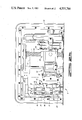
- FIGS. 2A-2B form a top plan view of the preferred embodiment of the reader unit of the present invention disposed in the bottom portion of its container.
- FIGS. 3A-3B are a schematic circuit diagram of the preferred embodiment of a video section and of a portion of a timing section of the reader unit.
- FIGS. 4A-4B are a schematic circuit diagram of the preferred embodiment of another portion of the timing section of the reader unit.
- FIGS. 5A, 5B and 5C are a schematic circuit diagram of the preferred embodiment of a motor control section of the reader unit.
- FIG. 6 is a partial sectional side elevational view of the preferred embodiment of the reader unit of the present invention.
- the present invention shown in the preferred embodiment in the drawings and described hereinbelow provides an automatic optical reader system which accurately reads indicia, such as graphic information contained on a drill stem test chart, and translates the indicia into numerical form to be used, for example, for transmission by telephone lines to a central computer for analysis.
- the automatic reader system is constructed to be powered from a standard commercial power source. Control is maintained with minimal operator interaction so that non-experts can operate the equipment of the automatic reader system.
- the automatic optical reader system is a data conversion instrument which comprises a reader unit 2 and a control processor (not shown in the drawings).
- the reader unit 2 and the control processor form optoelectronic means for automatically scanning indicia carried on a chart, such as a drill stem test chart 4 illustrated in FIG. 1B or any other suitable medium, and for automatically converting the indicia into electrical signals.
- the indicia to be scanned will be specifically identified as graphic data on the drill stem test chart 4.
- Chart 4 has scribed thereon graphic data 6 representing, in the preferred embodiment, pressure versus time information recorded during a drill stem test.
- the chart 4 in the preferred embodiment is a brass plate having a flat black coating which, when scribed by a bourdon tube pressure recording device stylus, yields a relatively light line on a relatively dark background.
- the preferred embodiment is disclosed to be used with such a chart having light indicia on a dark background, it is contemplated that the present invention can be used with dark indicia on a light background and with indicia other than graphic data.
- the chart has a surface having a size approximately four inches by five inches on which the graph 6 is recorded.
- FIGS. 1A-1B form a functional block diagram of the preferred embodiment of the reader unit 2.
- the reader unit 2 provides viewing means for viewing the surface of the chart 4 as an array of discrete informational units; and it also provides bit generating means for generating for each discrete unit one, and only one, respective electrical binary bit having one of two logic values depending upon whether the respective unit is detected as being relatively light or relatively dark as determined by comparison with a preset-table reference level.
- the viewing means of the reader unit 2 includes mount means for holding the chart 4 having the graphic data 6 thereon.
- the mount means is schematically shown in FIG. 1B as a drum or spindle or other rotatable element identified by the reference numeral 8.
- the drum 8 is illustrated as having the chart 4 mounted thereon.
- the mount means is further described subsequently with reference to FIG. 2B.
- the viewing means of the reader unit 2 also includes a portion of a sensor means 10 for sensing the graphic data and for converting the sensed graphic data into corresponding analog electrical signals. So that the chart 4 mounted on the drum means 8 is movable past the sensor means 10 in a first direction, the viewing means 2 further includes first drive means shown in FIG. 1B as including a drum motor 12 and a drum motor control circuit 14.
- the drum motor control circuit 14 has movement detection and encoding means 16 associated therewith for detecting how far and how fast the drum 8 is rotated by the motor 12.
- the viewing means further comprises second drive means including a stepper motor 18 and a stepper motor control circuit 20.
- the second drive means moves the sensor means 10 in a second direction relative to the graphic data 6 contained on the chart 4 mounted on the drum 8.
- the first drive means rotates the drum 8 and the chart 4 mounted thereon in front of the sensor means 10, and the second drive means moves the sensor means 10 in a direction substantially parallel to the longitudinal axis (i.e., the axis of rotation) of the drum 8.
- the preferred embodiment of the reader unit 2 also includes a timing means which forms part of the bit generating means.
- the timing means includes clock generator means 22, timing and phasing means 24, start scan logic means 26, video counter means 28, and byte detecting means 30.
- the bit generating means also includes a video portion which comprises a portion of the sensing means 10 and a binary conversion means 32 for comparing each of the electrical signals provided by the sensor means 10 to a predetermined reference level and for converting the electrical signals from the sensor means 10 above the reference level into respective binary bit signals each having a first logic value and for converting those electrical signals from the sensor means 10 below the reference level into respective binary bit signals each having a second logic value.
- FIG. 1B further shows that the reader unit 2 also includes a lamp and motor triac control circuit 34, camera power supply means 36, and power regulating means 38.
- FIGS. 2A-2B schematically illustrate the preferred assembly of the reader unit 2 contained in a portable container or housing 40 of a size suitable for being hand-carried by a person or otherwise portable.
- the container or housing 40 is substantially the size of a suitcase, and the container includes a lower or bottom portion 41 and an upper or top portion 43.
- the container 40 is preferably constructed of a durable substance to protect the reader unit 2 contained therein from the harsh environments in which the present invention is contemplated to be used.
- Mounted in the container 40 are electrical connectors 42 to which a cable (not shown) is connected for electrically coupling the reader unit 2 to the control processor which is contained in another housing similar to the housing 40 and which is used locally with the reader unit 2.
- the mount means which includes a drum or spool 44 which is integrally formed on a shaft 45 in the preferred embodiment and on which the chart 4 is mounted and held in place by clips 46 and blocks 47.
- the drum 44 which corresponds to the drum 8 schematically illustrated in FIG. 1B, is substantially cylindrical and made of stainless steel in the preferred embodiment.
- Each of the blocks 47 is adjustably mounted on the drum 44 by adjustment means shown as two screws 48 in FIG. 2B.
- Each of the clips 46 is pivotally mounted between respective ones of the blocks 47 by a rod 49.
- the clips 47 are variably positionable adjacent the drum 44 by appropriately tightening or loosening each of the screws 48.
- the reader unit 2 also includes a drum cover 51 (shown in FIG. 6) whose open or closed status is monitored by the control processor to insure that the cover 51 is closed during a reading operation of the present invention.
- the cover 51 is slidably disposed in a track formed in the housing 40 so that when the upper and lower portions of the housing 40 are connected, the cover 51 can be moved from a closed position (the position of the cover 51 shown in FIG. 6) to an open position in which the cover 51 is disposed below, or underlies, the drum 44 to catch the chart if it is dropped during the time one is trying to clip the chart to the drum or if it is otherwise not properly received by the drum 44 when the cover is at the open position.
- the reader unit 2 To rotate the drum 44 in a controllable manner, the reader unit 2 also includes a drum motor (corresponding to the motor 12 shown in FIG. 1B) which is contained in a housing 55 shown in FIG. 2B and which is coupled to the drum 44 and the shaft 45 by suitable means for transferring rotary motion from the motor to the drum 44.
- the precise position and speed of the drum on the shaft 45 is measured electronically by a postioner encoder means 57 of a type known in the art.
- the encoder 57 is illustrated in FIG. 1B as the element 16.
- the reader unit 2 also includes light receiving means comprising the sensor means 10 which in the preferred embodiment includes a camera or optical lens 52 and a photo-responsive element such as a Fairchild CCD 142 optical sensor (not visible in FIGS. 2A-2B).
- the optical lens 52, the photo-responsive element and the associated conditioning and timing circuitry are mounted on a suitable carriage means 54.
- carriage movement means is provided in the reader unit 2.
- the carriage movement means includes in the preferred embodiment shown in FIGS. 2A-2B a ball bearing lead screw 56 extending axially through a complementally constructed ball nut assembly 58 on which the optical lens 52 and the photoresponsive means are mounted.
- the carriage movement means also includes a stepper motor 60 (corresponding to the motor 18 shown in FIG. 1B) which is controlled to precisely position the optical lens 52 and the associated photo-responsive element so they detect segments or strips of the chart 4 as it is rotated by the drum motor disposed in the housing 55.
- FIGS. 3A-5C are also suitably mounted within the container 40.
- FIGS. 3A-5C are also suitably mounted within the container 40.
- FIG. 3A discloses the preferred embodiment circuits for the clock generator means 22, the timing and phasing means 24, and the photo-responsive element of the sensor means 10.
- the clock generator means 22 includes an integrated circuit timing pulse generator means 62 which is connected in the preferred embodiment to provide a nominal frequency of 3.00 MHz.
- the timing signal from the clock generator means 22 drives a plurality of flip-flops 64 included within the timing and phasing means 24.
- the timing and phasing means 24 provides five output signals. One of the outputs is identified as the ORG signal (a master control signal), another output is identified as a reset control signal, and the other three outputs are identified as being connected to a Fairchild CCD 142 integrated circuit optical sensor chip or photo-responsive element 66 previously mentioned as forming a part of the sensor means 10. The three outputs connected to the sensor means 10 control the operation of the photo-responsive element 66.
- the photo-responsive element 66 also has connected thereto suitable circuit means 68 of a type as is known in the art.
- the element 66 provides an output along a conductor means 70 which is connected to an input of a video amplifier means 72 forming a part of the binary conversion means 32 and having a preferred embodiment circuit as shown in FIG. 3B.
- the video amplifier means 72 appropriately amplifies the output signal received along the conductor means 70 from the integrated circuit optical sensor 66.
- the amplified signal from the video amplifier means 72 is provided to a first input of a comparator means 76 having a preferred embodiment as shown in FIG. 3B.
- the reference level signal Connected to a second input of the comparator means 76 is the reference level signal which is used to determine whether a relatively dark portion or a relatively light portion has been detected on the chart 4. If the video amplifier output signal is below the value of the reference signal on the second input of the comparator means 76, a relatively dark portion has been detected; if the video amplifier output signal is above the reference level signal, a relatively light portion of the chart 4 has been detected.
- a flip-flop 78 When a relatively dark portion has been detected, a flip-flop 78 provides a binary bit in the form of an electrical signal having a magnitude representing a low or "0" logic level. When a relatively light portion has been detected, the flip-flop or latch 78 provides a binary bit in the form of an electrical signal having a magnitude representing a high or "1" logic level. These binary bits form the binary video signals as labeled in FIG. 3B.
- the reference level signal is determined by summing via a summing means 80 a threshold signal generated by the control processor and a signal provided by a black background clamp sample hold means 82 having a preferred embodiment circuit shown in FIG. 3B.
- the black background clamp sample hold means 82 is responsive to a valid video signal initiated by a first-sixteen counter means 84 shown in FIG. 1A (and more particularly shown in FIG. 4B) and a chart valid signal generated in the control processor unit in response to an indexing signal and a one mil signal shown in FIG. 5B.
- the summing means 80 and the means 82 form a reference level setting means.
- the elements 72, 76, 78, 80, 82, and 84 form the binary conversion means 32 shown in FIG. 1A.
- FIGS. 4A-4B show additional preferred embodiment circuits of the reader unit 2. Shown in FIG. 4A are the start scan logic means 26 and the byte strobe means 30.
- the start scan logic means 26 includes flip-flops 86 which are responsive to the reset control signal provided by the timing and phasing means 24 shown in FIG. 3A.
- the flip-flops 86 provide a set signal and a start scan signal which are transmitted to the timing and phasing means 24 as shown by the continuous lines which are similarly labeled in FIG. 3A and FIG. 4A.
- the start scan logic means 26 also includes flip-flops 88 which are responsive to the one mil signal subsequently described and the clock signal from the clock generator means 22 shown in FIG. 3A.
- the byte strobe means 30 includes combinational logic byte detecting means 90 shown in FIG. 4A.
- the byte detecting means 90 is responsive to the video counter means 28 particularly shown in FIG. 4B and to the ORG signal provided by the timing and phasing means 24.
- the byte detecting means 90 is responsive to each eighth count counted by the video counter means 28 so that a byte strobe signal is provided thereby defining a byte of video information to include eight bits. More broadly, the byte detecting means responds to each nth count to define a byte to have n bits.
- FIG. 4B discloses the first-sixteen counter means 84, the video counter means 28 and an EOS trigger means 92.
- the first sixteen counter means 84 generates the valid video signal after sixteen ORG pulses have been detected after the receipt of an EOS signal.
- the video counter means 28 includes three binary counter integrated circuits which count 2,048 ORG pulses before activating the generation of the EOS signal.
- the signal from the video counter means 28 indicating that 2,048 pulses have been counted is provided to the EOS trigger means 92 for generating the EOS signal.
- the ORG signal is the master clocking signal and the EOS signal is the master resetting signal of the present invention.
- the one mil signal is the primary "start scan" signal.
- FIG. 5A discloses the preferred embodiment circuit of the stepper motor control means 20 for providing the drive energization to the stepper motor 60 shown in FIG. 2A and corresponding to the motor 18 shown in FIG. 1B.
- the stepper motor control means 20 includes left and right limit switch inputs 94 which are connected to suitable switch means 95 (shown in FIGS. 1B and 2B) which can be actuated to limit the left and right movement of the lens 52 and the photo-responsive element 66 along the screw 56 shown in FIG. 2B.
- the stepper motor control means 20 also includes inputs for receiving a step trigger signal and a direction signal from the control processor for controlling a stepping motor control integrated circuit means 96 of the type known in the art.
- the integrated circuit means 96 provides the proper sequence of signals to drive transistors 98 which interface the stepper motor control means 20 to the stepper motor 60 to thereby cause the motor to provide either forward or reverse rotation.
- the stepper motor control means 20 is controlled to move the optical lens 52/integrated circuit sensor 66 combination in precise increments so that strips or segments of the chart 4 are read as the drum 44 rotates. Once a strip or segment of the chart 4 has been read, the stepper motor control means 20 is activated to drive the stepper motor 60 so that the lens 52 and the integrated circuit sensor 66 are moved a predetermined distance to read the next strip or segment of the chart 4.
- FIG. 5B discloses the preferred embodiment circuits of the one mil buffer and drum motor control means 14.
- the preferred embodiment includes an encoder signal receiving section 100 which receives the input from the encoder 57 associated with the drum 44 (schematically shown in FIG. 1B as the encoder 16 and the drum 8).
- the encoder signal receiving section 100 detects when the drum motor in the housing 55 has rotated the drum 44 one mil. When this occurs, the encoder receiving section 100 provides a signal to a switch means 102.
- the switch means 102 is manually switchable to select as a one mil signal either the output of an EXCLUSIVE NOR gate 104 forming a portion of the encoder receiving means 100 or the output of an auxiliary timer means 106 for synthesizing or imitating the one mil signal so that the camera circuits can be tested without the drum 44 rotating.
- a frequency-to-voltage converter means 108 which activates a drum motor drive circuit 110 to actuate and control the drum motor.
- FIG. 5C discloses the preferred embodiment circuit of the lamp and motor triac control means 34, the camera power supply means 36, and the circuit elements utilized to provide regulated power sources.
- the lamp and motor triac control means 34 is responsive to a drum cover interlock signal indicating the status of the drum cover. When the drum cover 51 is closed (thereby engaging the switch 53), the lamp and motor triac control means 34 illuminates the lamp 50.
- the control processor unit mentioned hereinabove with respect to the means for controlling the operation of the reader unit 2 includes any suitable type of control device.
- the processor unit comprises microcomputer means including a Digital Equipment Corporation LSI-11/23 16-bit microprocessor, 64k words of read/write memory (RAM), and 16k words of non-volatile program and data table memory (ROM).
- the microcomputer means controls the operation of the reader unit 2 from power-up to power-down.
- the 16k words of ROM contain all the words of the programs needed to operate the reader unit 2.
- the chart 4 has scribed thereon the pressure versus time line 6.
- This line is created by placing the chart 4 in a downhole tool, such as described hereinabove, so that a pressure responsive member can scribe on the chart 4 a line representing the detected pressure over a known time period.
- the scribed line 6 in the preferred embodiment is a shiny line on a dark background because the chart 4 is a brass sheet coated with a flat black paint.
- the present invention can be constructed to also function with a relatively dark indicia on a relatively light background.
- the chart is retained on the stainless steel drum 44 by means of the clips 46.
- the apparatus 2 is actuated to read the chart, the light 50 is illuminated so that a brilliant light is reflected from the surface of the chart 4 into the eye of the lens 52 focused on the chart and thus to the photo-responsive element 66.
- the shinier the surface of the chart the less the light is diffused before reaching the camera lens; conversely, the duller the surface of the chart, the more the light is diffused.
- the video portion of the reader unit 2 classifies the light as either negligible or intense. Areas of the chart which reflect negligible light are considered black. Areas of the chart which reflect intense light are considered scribed lines.
- the decision whether the reflected light detected by the optical lens 52 and the photo-responsive member 66 associated therewith constitutes a black area or a light area (which light area would indicate the scribed line 6) is made by the video portion of the reader unit 2.
- This portion is generally identified in FIG. 1A and more particularly shown in FIGS. 3A and 3B. Broadly, these elements compare the analog electrical signal from the CCD 142 sensor 66 (the photo-responsive member) with the reference level established at the output of the summing means 80. If the analog signal from the sensor 66 is below the reference level, the video portion determines that a dark region has been observed; if the analog value is above the reference level, the video portion determines that a light area has been detected.
- the output of the latch means 78 provides a logical low level or "0" bit; if a light area has been detected, the output of the latch means 78 is a logical high level or "1" bit.
- the series of electrical zeros and ones provided by the latch means 78 constitutes the binary video signal labeled in the drawings.
- the present invention divides the chart 4 into substantially equal discrete areas which are viewed and then converted into respective binary bits depending upon whether the viewed area is determined to be a dark or a light area.
- the chart 4 is a four inch by five inch metal sheet.
- the surface of this chart in which the pressure versus time graph is scribed is viewed as a collection or array of one-half mil by one mil areas.
- the preferred embodiment of the present invention converts the four inch by five inch surface area into 4 ⁇ 10 7 bits of serial binary data when an entire chart has been read. It is to be noted that different types, sizes and areas of the charts or other media can be read by the present invention, but the preferred embodiment disclosed herein is particularly adapted to read four inch by five inch drill stem test charts in one-half mil by one mil areas.
- This division into discrete areas is achieved by appropriately controlling the operation of the drum motor in the housing 55 (motor 12 in FIG. 1B) and the stepper motor 60 (motor 18 in FIG. 1B).
- the drum motor is controlled to rotate the chart 4 mounted on the drum 44 in one mil increments.
- This control is achieved through feedback provided by the encoder means 57 (encoder 16 in FIG. 1B) which detects how far and how fast the drum 44 is rotated by the drum motor.
- the stepper motor 60 is controlled in the preferred embodiment to move the optical lens 52 and the photo-responsive element 66 in four increments axially with respect to the length of the drum 44.
- the drum motor is actuated and the lamp 110 is illuminated, then the stepper motor 60 is actuated to move the lens 52 and photo-responsive element 66 to the right end of the chart 4 mounted on the drum 44 as indicated by hatched line 112 shown in FIG. 2B.
- the chart on the drum 44 is sampled in one mil increments until the entire quarter strip is read.
- stepper motor 60 is actuated to move the lens 52 and element 66 one increment to the left to read the next quarter strip of data contained on the chart 4.
- the chart on the drum is read again until the entire strip is read.
- the third and fourth quarter strips to the left of the first two strips are read by the optical lens and photo-responsive element.
- the stepper motor 60 Upon reading the entire chart, the stepper motor 60 is actuated to return the lens 52 and photo-responsive element 66 to the right-most position and the drum motor is deactivated to stop the drum 44 from rotating. The read lamp 50 is then extinguished.
- each of the one-half mil by one mil areas is viewed and analyzed to be either a light or dark area as signified by the electrical "ones" and "zeros" of the binary video stream of electrical binary signals.
- This feature of viewing a surface as an array of discrete areas, reading every discrete area as a light or dark area and converting each area into a respective one of two binary signals is an important feature of the present invention.
- Timing control for the reading operation is maintained by the timing portion of the present invention generally shown in FIG. 1A and more particularly shown in FIGS. 3A and 4A-4B.
- the primary or master timing signal is the ORG signal generated by the timing and phasing circuit 24 shown in FIG. 3A.
- the present invention determines that valid video information can be received. This is indicated by the valid video signal labeled in FIG. 4B.
- the video counter means 28 counts up to 2,048 pulses of the ORG signal.
- the EOS signal is generated by the EOS trigger means 92 to reset the timing of the apparatus.
- the one mil signal initiates the "start scan" signal.
- the apparatus initially automatically determines the optical read threshold needed to locate and distinguish the shiny scribed lines of the graph 6 from the flat black background of the chart 4.
- the apparatus then divides the chart into one-inch strips along the time axis to accommodate the one-inch fields of view of the lens 52 and photo-responsive element 66.
- the reader unit 2 reads each strip in one-half mil by one mil resolution as a sequence of bits by using the bright light 50, the lens 52 and the electronic photo-responsive element 66. Once a single strip has been processed, the camera carriage is moved to the next strip and the operation loops back to process this next strip. This process continues until all strips of the chart 4 have been processed.
- the present invention can be constructed to read indicia other than graphic data contained on a drill stem test chart.
Landscapes
- Engineering & Computer Science (AREA)
- Multimedia (AREA)
- Signal Processing (AREA)
- Image Input (AREA)
Abstract
Description
Claims (6)
Priority Applications (1)
| Application Number | Priority Date | Filing Date | Title |
|---|---|---|---|
| US06/355,465 US4551766A (en) | 1982-03-08 | 1982-03-08 | Optical reader |
Applications Claiming Priority (1)
| Application Number | Priority Date | Filing Date | Title |
|---|---|---|---|
| US06/355,465 US4551766A (en) | 1982-03-08 | 1982-03-08 | Optical reader |
Publications (1)
| Publication Number | Publication Date |
|---|---|
| US4551766A true US4551766A (en) | 1985-11-05 |
Family
ID=23397517
Family Applications (1)
| Application Number | Title | Priority Date | Filing Date |
|---|---|---|---|
| US06/355,465 Expired - Fee Related US4551766A (en) | 1982-03-08 | 1982-03-08 | Optical reader |
Country Status (1)
| Country | Link |
|---|---|
| US (1) | US4551766A (en) |
Cited By (1)
| Publication number | Priority date | Publication date | Assignee | Title |
|---|---|---|---|---|
| WO2006001716A1 (en) | 2004-06-23 | 2006-01-05 | Sharpin Rosemary Katherine Cam | Improvements in and relating to micro-organism test apparatus and methods of using the same |
Citations (21)
| Publication number | Priority date | Publication date | Assignee | Title |
|---|---|---|---|---|
| US3256480A (en) * | 1965-03-29 | 1966-06-14 | Chevron Res | Method of detecting geologically anomalous bodies lateral to a well bore by comparing electrical resistivity measurements made using short-spaced and long-spaced electrode systems |
| US3435134A (en) * | 1966-03-21 | 1969-03-25 | Rca Corp | Digital television data compression system |
| US3457544A (en) * | 1968-02-06 | 1969-07-22 | Schlumberger Technology Corp | Methods and apparatus for recording well logging data |
| US3553362A (en) * | 1969-04-30 | 1971-01-05 | Bell Telephone Labor Inc | Conditional replenishment video system with run length coding of position |
| US3609244A (en) * | 1969-12-18 | 1971-09-28 | Bell Telephone Labor Inc | Conditional replenishment video system with variable length address code |
| US3872248A (en) * | 1973-02-16 | 1975-03-18 | Exxon Research Engineering Co | Facsimile apparatus |
| US3876825A (en) * | 1972-06-30 | 1975-04-08 | Tokyo Shibaura Electric Co | Facsimile signal transmission apparatus |
| US3882305A (en) * | 1974-01-15 | 1975-05-06 | Kearney & Trecker Corp | Diagnostic communication system for computer controlled machine tools |
| US3955045A (en) * | 1974-03-08 | 1976-05-04 | Exxon Research And Engineering Company | Method and apparatus for time compression of facsimile transmissions |
| US4001500A (en) * | 1974-11-21 | 1977-01-04 | Xerox Corporation | Amplifier for use in a document scanning system |
| US4020462A (en) * | 1975-12-08 | 1977-04-26 | International Business Machines Corporation | Method and apparatus for form removal from contour compressed image data |
| US4055763A (en) * | 1975-03-31 | 1977-10-25 | Schlumberger Technology Corporation | Neutron characteristic and spectroscopy logging methods and apparatus |
| US4157659A (en) * | 1978-02-27 | 1979-06-12 | Resource Control Corporation | Oil well instrumentation system |
| US4254439A (en) * | 1979-12-26 | 1981-03-03 | International Business Machines Corporation | Facsimile mid-page restart |
| US4258421A (en) * | 1978-02-27 | 1981-03-24 | Rockwell International Corporation | Vehicle monitoring and recording system |
| US4297727A (en) * | 1979-07-09 | 1981-10-27 | Ricoh Company, Ltd. | Facsimile apparatus |
| US4310887A (en) * | 1972-08-28 | 1982-01-12 | Schlumberger Technology Corporation | Verification and calibration of well logs and reconstruction of logs |
| US4312040A (en) * | 1970-09-09 | 1982-01-19 | Schlumberger Limited | Well log depth aligning |
| US4327379A (en) * | 1980-04-11 | 1982-04-27 | Xerox Corporation | Hardware implementation of 4-pixel code encoder |
| US4335277A (en) * | 1979-05-07 | 1982-06-15 | Texas Instruments Incorporated | Control interface system for use with a memory device executing variable length instructions |
| US4390953A (en) * | 1980-11-10 | 1983-06-28 | Kearney & Trecker Corporation | Unmanned diagnostic communications system for computer controlled machine tools |
-
1982
- 1982-03-08 US US06/355,465 patent/US4551766A/en not_active Expired - Fee Related
Patent Citations (21)
| Publication number | Priority date | Publication date | Assignee | Title |
|---|---|---|---|---|
| US3256480A (en) * | 1965-03-29 | 1966-06-14 | Chevron Res | Method of detecting geologically anomalous bodies lateral to a well bore by comparing electrical resistivity measurements made using short-spaced and long-spaced electrode systems |
| US3435134A (en) * | 1966-03-21 | 1969-03-25 | Rca Corp | Digital television data compression system |
| US3457544A (en) * | 1968-02-06 | 1969-07-22 | Schlumberger Technology Corp | Methods and apparatus for recording well logging data |
| US3553362A (en) * | 1969-04-30 | 1971-01-05 | Bell Telephone Labor Inc | Conditional replenishment video system with run length coding of position |
| US3609244A (en) * | 1969-12-18 | 1971-09-28 | Bell Telephone Labor Inc | Conditional replenishment video system with variable length address code |
| US4312040A (en) * | 1970-09-09 | 1982-01-19 | Schlumberger Limited | Well log depth aligning |
| US3876825A (en) * | 1972-06-30 | 1975-04-08 | Tokyo Shibaura Electric Co | Facsimile signal transmission apparatus |
| US4310887A (en) * | 1972-08-28 | 1982-01-12 | Schlumberger Technology Corporation | Verification and calibration of well logs and reconstruction of logs |
| US3872248A (en) * | 1973-02-16 | 1975-03-18 | Exxon Research Engineering Co | Facsimile apparatus |
| US3882305A (en) * | 1974-01-15 | 1975-05-06 | Kearney & Trecker Corp | Diagnostic communication system for computer controlled machine tools |
| US3955045A (en) * | 1974-03-08 | 1976-05-04 | Exxon Research And Engineering Company | Method and apparatus for time compression of facsimile transmissions |
| US4001500A (en) * | 1974-11-21 | 1977-01-04 | Xerox Corporation | Amplifier for use in a document scanning system |
| US4055763A (en) * | 1975-03-31 | 1977-10-25 | Schlumberger Technology Corporation | Neutron characteristic and spectroscopy logging methods and apparatus |
| US4020462A (en) * | 1975-12-08 | 1977-04-26 | International Business Machines Corporation | Method and apparatus for form removal from contour compressed image data |
| US4258421A (en) * | 1978-02-27 | 1981-03-24 | Rockwell International Corporation | Vehicle monitoring and recording system |
| US4157659A (en) * | 1978-02-27 | 1979-06-12 | Resource Control Corporation | Oil well instrumentation system |
| US4335277A (en) * | 1979-05-07 | 1982-06-15 | Texas Instruments Incorporated | Control interface system for use with a memory device executing variable length instructions |
| US4297727A (en) * | 1979-07-09 | 1981-10-27 | Ricoh Company, Ltd. | Facsimile apparatus |
| US4254439A (en) * | 1979-12-26 | 1981-03-03 | International Business Machines Corporation | Facsimile mid-page restart |
| US4327379A (en) * | 1980-04-11 | 1982-04-27 | Xerox Corporation | Hardware implementation of 4-pixel code encoder |
| US4390953A (en) * | 1980-11-10 | 1983-06-28 | Kearney & Trecker Corporation | Unmanned diagnostic communications system for computer controlled machine tools |
Cited By (4)
| Publication number | Priority date | Publication date | Assignee | Title |
|---|---|---|---|---|
| WO2006001716A1 (en) | 2004-06-23 | 2006-01-05 | Sharpin Rosemary Katherine Cam | Improvements in and relating to micro-organism test apparatus and methods of using the same |
| US20090111173A1 (en) * | 2004-06-23 | 2009-04-30 | Rosemary Katherine Cameron Sharpin | Micro-Organism Test Apparatus and Methods of Using the Same |
| US8642323B2 (en) | 2004-06-23 | 2014-02-04 | Zyzeba Testing Limited | Container for testing for micro-organisms |
| US9260740B2 (en) * | 2004-06-23 | 2016-02-16 | Zyzeba Testing Limited | Micro-organism test apparatus and methods of using the same |
Similar Documents
| Publication | Publication Date | Title |
|---|---|---|
| CA1192319A (en) | Method and apparatus for x-ray fluorescence spectroscopy | |
| US4195349A (en) | Self calibrating environmental condition sensing and recording apparatus | |
| CA2278108A1 (en) | Three-dimensional measurement method and apparatus | |
| US3853004A (en) | Methods and systems for measuring, displaying and recording time-rate of penetration | |
| CZ316494A3 (en) | Method of determining position of a body and apparatus for making the same | |
| US4462159A (en) | Reference mark selection system for measuring apparatus | |
| EP0050195A3 (en) | Method and devices for the selection of reference marks at incremental length or angle measuring devices | |
| US5299359A (en) | Method and system for measurement of internal tube dimensions within a wellbore | |
| US4531189A (en) | Data conversion, communication and analysis system | |
| US4551766A (en) | Optical reader | |
| EP0080294B1 (en) | Pattern scanners | |
| WO2022266239A1 (en) | Digital linear measuring device | |
| LV10532B (en) | A general-purpose measuring implement usable in the field, and its data transfer method | |
| US3440537A (en) | Bar-graph display instrument | |
| US3696397A (en) | Graph-reading digital converter | |
| Chaput et al. | Evaluation of an electronic fish measuring board | |
| CA1070429A (en) | Method for the automatic location of particular zones of a surface and an installation for the application of said method | |
| US4227246A (en) | Multi-parameter measurement system for fluids | |
| US3449725A (en) | Automatic digital data processing system for continuous flow analysis | |
| CN2276988Y (en) | On-line detector for length of oil pipe | |
| GB2164454A (en) | A pump for evaluating mineral samples | |
| GB1376408A (en) | Analogue data recording system | |
| US4110615A (en) | Automatic radiochromatagram strip scanner | |
| Cox | Logging data in digital form | |
| Coleman et al. | On-line automatic high speed inspection of cartridge cases |
Legal Events
| Date | Code | Title | Description |
|---|---|---|---|
| AS | Assignment |
Owner name: HALLIBURTON COMPANY, DUNCAN, OKLA. A CORP. OF DE. Free format text: ASSIGNMENT OF ASSIGNORS INTEREST.;ASSIGNOR:PENN, JACK C.;REEL/FRAME:003987/0073 Effective date: 19820422 Owner name: HALLIBURTON COMPANY, DUNCAN, OKLA. A CORP. OF DE. Free format text: ASSIGNMENT OF ASSIGNORS INTEREST.;ASSIGNOR:MOON, JOHN J.;REEL/FRAME:003987/0074 Effective date: 19820405 Owner name: HALLIBURTON COMPANY, DUNCAN, OKLA. A CORP. OF DE. Free format text: ASSIGNMENT OF ASSIGNORS INTEREST.;ASSIGNORS:MOSIER, JOHN E.;SURJAATMADJA, JIM B.;REEL/FRAME:003987/0075 Effective date: 19820405 Owner name: HALLIBURTON COMPANY, OKLAHOMA Free format text: ASSIGNMENT OF ASSIGNORS INTEREST;ASSIGNOR:PENN, JACK C.;REEL/FRAME:003987/0073 Effective date: 19820422 Owner name: HALLIBURTON COMPANY, OKLAHOMA Free format text: ASSIGNMENT OF ASSIGNORS INTEREST;ASSIGNOR:MOON, JOHN J.;REEL/FRAME:003987/0074 Effective date: 19820405 Owner name: HALLIBURTON COMPANY, OKLAHOMA Free format text: ASSIGNMENT OF ASSIGNORS INTEREST;ASSIGNORS:MOSIER, JOHN E.;SURJAATMADJA, JIM B.;REEL/FRAME:003987/0075 Effective date: 19820405 |
|
| CC | Certificate of correction | ||
| FEPP | Fee payment procedure |
Free format text: PAYOR NUMBER ASSIGNED (ORIGINAL EVENT CODE: ASPN); ENTITY STATUS OF PATENT OWNER: LARGE ENTITY |
|
| FPAY | Fee payment |
Year of fee payment: 4 |
|
| FPAY | Fee payment |
Year of fee payment: 8 |
|
| REMI | Maintenance fee reminder mailed | ||
| LAPS | Lapse for failure to pay maintenance fees | ||
| FP | Lapsed due to failure to pay maintenance fee |
Effective date: 19971105 |
|
| STCH | Information on status: patent discontinuation |
Free format text: PATENT EXPIRED DUE TO NONPAYMENT OF MAINTENANCE FEES UNDER 37 CFR 1.362 |