US45455A - Improved engine turning lathe - Google Patents
Improved engine turning lathe Download PDFInfo
- Publication number
- US45455A US45455A US45455DA US45455A US 45455 A US45455 A US 45455A US 45455D A US45455D A US 45455DA US 45455 A US45455 A US 45455A
- Authority
- US
- United States
- Prior art keywords
- tool
- plate
- work
- engraving
- motion
- Prior art date
- Legal status (The legal status is an assumption and is not a legal conclusion. Google has not performed a legal analysis and makes no representation as to the accuracy of the status listed.)
- Expired - Lifetime
Links
- 230000000694 effects Effects 0.000 description 24
- 239000000203 mixture Substances 0.000 description 18
- 230000036633 rest Effects 0.000 description 12
- 230000000875 corresponding Effects 0.000 description 8
- 230000001105 regulatory Effects 0.000 description 6
- 239000002023 wood Substances 0.000 description 6
- 102100001605 AKAP12 Human genes 0.000 description 4
- 101710011886 AKAP12 Proteins 0.000 description 4
- 241000220317 Rosa Species 0.000 description 4
- XEEYBQQBJWHFJM-UHFFFAOYSA-N iron Chemical compound [Fe] XEEYBQQBJWHFJM-UHFFFAOYSA-N 0.000 description 4
- 230000004301 light adaptation Effects 0.000 description 4
- 230000000284 resting Effects 0.000 description 4
- 229910001369 Brass Inorganic materials 0.000 description 2
- 229910001018 Cast iron Inorganic materials 0.000 description 2
- 229910000831 Steel Inorganic materials 0.000 description 2
- 238000005299 abrasion Methods 0.000 description 2
- 239000010951 brass Substances 0.000 description 2
- 150000001875 compounds Chemical class 0.000 description 2
- 238000010276 construction Methods 0.000 description 2
- 230000001066 destructive Effects 0.000 description 2
- 238000004534 enameling Methods 0.000 description 2
- 229910052742 iron Inorganic materials 0.000 description 2
- 210000001699 lower leg Anatomy 0.000 description 2
- 238000004519 manufacturing process Methods 0.000 description 2
- 239000002184 metal Substances 0.000 description 2
- 229910052751 metal Inorganic materials 0.000 description 2
- 230000004048 modification Effects 0.000 description 2
- 238000006011 modification reaction Methods 0.000 description 2
- 239000010959 steel Substances 0.000 description 2
Images


Classifications
-
- B—PERFORMING OPERATIONS; TRANSPORTING
- B23—MACHINE TOOLS; METAL-WORKING NOT OTHERWISE PROVIDED FOR
- B23Q—DETAILS, COMPONENTS, OR ACCESSORIES FOR MACHINE TOOLS, e.g. ARRANGEMENTS FOR COPYING OR CONTROLLING; MACHINE TOOLS IN GENERAL CHARACTERISED BY THE CONSTRUCTION OF PARTICULAR DETAILS OR COMPONENTS; COMBINATIONS OR ASSOCIATIONS OF METAL-WORKING MACHINES, NOT DIRECTED TO A PARTICULAR RESULT
- B23Q35/00—Control systems or devices for copying directly from a pattern or a master model; Devices for use in copying manually
- B23Q35/04—Control systems or devices for copying directly from a pattern or a master model; Devices for use in copying manually using a feeler or the like travelling along the outline of the pattern, model or drawing; Feelers, patterns, or models therefor
- B23Q35/08—Means for transforming movement of the feeler or the like into feed movement of tool or work
- B23Q35/10—Means for transforming movement of the feeler or the like into feed movement of tool or work mechanically only
- B23Q35/101—Means for transforming movement of the feeler or the like into feed movement of tool or work mechanically only with a pattern composed of one or more lines used simultaneously for one tool
- B23Q35/102—Means for transforming movement of the feeler or the like into feed movement of tool or work mechanically only with a pattern composed of one or more lines used simultaneously for one tool of one line
-
- Y—GENERAL TAGGING OF NEW TECHNOLOGICAL DEVELOPMENTS; GENERAL TAGGING OF CROSS-SECTIONAL TECHNOLOGIES SPANNING OVER SEVERAL SECTIONS OF THE IPC; TECHNICAL SUBJECTS COVERED BY FORMER USPC CROSS-REFERENCE ART COLLECTIONS [XRACs] AND DIGESTS
- Y10—TECHNICAL SUBJECTS COVERED BY FORMER USPC
- Y10T—TECHNICAL SUBJECTS COVERED BY FORMER US CLASSIFICATION
- Y10T82/00—Turning
- Y10T82/13—Pattern section
- Y10T82/135—Cam-controlled cutter
-
- Y—GENERAL TAGGING OF NEW TECHNOLOGICAL DEVELOPMENTS; GENERAL TAGGING OF CROSS-SECTIONAL TECHNOLOGIES SPANNING OVER SEVERAL SECTIONS OF THE IPC; TECHNICAL SUBJECTS COVERED BY FORMER USPC CROSS-REFERENCE ART COLLECTIONS [XRACs] AND DIGESTS
- Y10—TECHNICAL SUBJECTS COVERED BY FORMER USPC
- Y10T—TECHNICAL SUBJECTS COVERED BY FORMER US CLASSIFICATION
- Y10T82/00—Turning
- Y10T82/14—Axial pattern
- Y10T82/141—Axial pattern having transverse tool and templet guide
Definitions
- My lathe is designed to be used for the purposes of engraving and of ornamenting jewelry, silver-ware, &c., and may also be used for engraving dies, for stamping work, for enameling, and for other purposes.
- lt is designed to take the place of the machine known as the Rose Engine-Lathej7 by which these styles of work are. usually performed, but which is subjectto several disadvantages, one of the most prominent of which is that as the main shaft and its rosettes or patterns with the work to be engraved must all vibrate bodily to wave the line, and the aggregated weight of these being very considerable, their consequent great inertia renders it impracticable t0 run the lathe at anything more than a very low speed.
- the vibration of the work ioproy cute the waved line necessarily causes it to approach and recede from the rest which supports the cutting'tool, and as the vibration of the work must necessarily be either in a line parallel to the mandrel or at right'angles to it, this motion to and from the rest is necessarily at some angles very considerable, and involves a corresponding advance and withdrawal ofthe tool at each vibration.
- My machine is also designed to do a large porticn of those kinds of work which are now done on the machine known as the geometrical lathe 7 for bank-note work and other purposes.
- the geometrical lathe 7 for bank-note work and other purposes.
- My invention consists in, iist, the combil nation of cams or projections Ona revolving tion causes the wave to vary considerably in bination of an eccentric and one or more cams or rosettes with each other and with i other parts which connect'lthem to the Ylengraving-tool in such a manner that the motions produced by both are combined and transmitted to the engravingtool, substantially as hereinafter more fully set forth; fourth, the combination, with an engravingtool and a guide or follower by which its depth is regulated, of an eccentric and connecting parts in such a manner that the engraving-tool will be withdrawn periodically from the surface of the plate or other work to be engraved by the action ofthe mechanism, as hereinafter more fully set forth fifth, the combination, with an engraving-tool and a guide or follower by which its depth is regulated, of one or more cams or rosettes and connecting parts in such a manner that the engraving-tool will or maybe withdrawn, from time to time, from the surface of the work to vary the'figures by the action of the
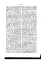
- Figure l is an end elevation of my improved lathe.
- Fig. 2 is a plan ofthe engraving-tool and rest, showing the tool in position to operate upon an angular surface.
- Fig. 3 is a detail View showing in side elevation the sliding tool-holder, theengravin g-tool, the gage or guide by which the depth of the operation of the engravingtool is regulated, andk the arm or bell-crank,- which is used in connection with other parts for retracting or withdrawing the engravingtool from the work.
- Fig. et isa general plan of the machine.
- Fig. 5 gives detailed views of the tool-slide and ofthe several upper works upon which it is mounted. In this figure No.
- Fig. 6 is a plan of some of the internal mechanism ofthe rest by which the motion given by the cams or rosettes and eccentric is communicated to the engraving-tool.
- Fig. 7 is a section of the same parts.
- Fig. 8 is a plan of a table by which the motion from the eccentric and rosettes or cams is communicated to the engraving-to'ol.
- Fig. 9 is a side view of the same thing.
- FigQlO is a detail elevation showing a'n end view of the rest upon which the engraving-tool is mounted, and also showing the connection of various parts for transmitting the motion of the rosettes and'eccentric to the engraving-tool.
- A is the pcd-plate of the machine, which, should be made of cast-iron, though in the drawings it is represented as being made of wood. It is proper to remark here that none ofthe parts of this machine should be made of wood, and that all the parts which are represented in the drawings as wood should be made of iron, steel, or brass.
- B is the mandrel of the lathe. Itis mounted in bearings in the usual manner, is provided with a face-plate, C, on which to place the work, and carries a spur-wheel, D, which gears into another spur-wheel, E, on the shaft F.
- the wheel E gears into a pinion, Gr, on the clutch-shaft H, which latter is mounted on the shaft I.
- the shaft I carries a bevel-wheel, J, which meshes into another bevel-wheel, K, on the shaft L, to which latter the crank M is attached.
- the machine is put in motion by turning this crank M, and from this point it is easy to trace the motion through the connections already described to the mandrel B.
- the bevel-wheel K also meshes into a bevel-wheel,
- This shaft O has a groove, P, running nearly its entire length, as shown iii lr ⁇ ig.1,to receive a corresponding rib, which projects inwardly from the piece or cylinder upon which the eccentric and ,rosettes are formed, as shown in Q is an eccentric which is accurately fitted on the shaft O, and has a rib projecting inwardly therefrom to tit into the groove P in the shaft O.
- R is a piece of metal on which a series of cams or rosettes are formed to aid in the production of the pattern desired. Theserosettes may be formed separately; butI preferto make them all in one piece.
- the eccentric Q and the rosettes it form the pattern engraved by giving motion to the engraving-tool.
- S is an eccentric-strap, which surrounds the eccentric Q, and by means of the rod T con ⁇ iiects it with the slide U.
- This slide has la pin, V, inserted in it, which supports and operates upon the lit'ter ⁇ V. communicating to it a vertical motion derived from the revolution ofthe ecceiitiic Q.
- This lifter W is made in one piece with shaft a and the arms b. These last support a cross-head, c, which is adjusted thereon by means of a thumb-screw, d, the ob' ject of this a lj ustineiit being to vary the effect of the eccentric upon the motion of the tool.
- This cross-head or cross-bai' c supports one end ofthe frame c, the other end of which is supported by the similar cross-headf.
- This crosshead fis supported on arms g, of similar construction to the arms I), and t'ornied in like inaiiiieriii one piece with the shaft li. Itis also similarly adjusted bynieansot'the thumb-screw t.
- a lifter, j similar to the iit'ter 7, projects fi oni the shatt l1, and is operated by the slide lr, which latter receives motion from the cams or rosettes formed upon the cylinder it through tre intervention of the stops or touches l. These stops or touches l are all hung in a.
- the motion thus produced is communicated to the slide 7s by means of a projectingpiece, s, which extends under a shoulder on the said slide.
- the motion thus communicated to this slide is in its turn imparted to the lifter j by means of the pin t and through said lifter and the frame of which it forms a part to the frame c, in the manner already described in relation to the I communication of the motion of the eccentric to the other end of the said frame.
- a shaft, u extends transversely through the middle of the frame c, which shaft supports one end of each of the bars 'v and tr, the other end of the bars c being supported by the shaft a, and the other end of the bars te being supported by the shaft l1, on each of which bearings they are permitted to vibrate.
- a pin, 1, is fixed in each of these levers or bars c and w for the downwardiy-projecting lugs 2 and 3 of the platform 4 to rest on. These pins I place at the same relative distance between the xed and movable bearing .in all these bars.
- the lugs 2, as will be perceived, are notched, as represented in Fier. 9, to prevent the platform from getting out of its place upon the. pins.
- the tool-stock 6 is also fitted to slide freely in a dovetail groove in the toolplate 10, in which it is mounted, and may be kept up to the work by the pressure of the. hand or by a spring, as may be desired.
- the separate plate l1 For the purpose of accurate adjustment of the width of the groove to the width of the toolstock, one side of it is formed by the separate plate l1, as shown in No.
- the toolplate 1t is mounted on the swing-plate 12 in such a manner as to allow it to slide smoothly and with tolerable ease for a short distance in ahorizontal direction transverse to the line of motion in which the toolstock 6 .slides in the tool-plate 10.
- the swing-plate 12 is mounted upon the plate 18, which forms a part of the sliding carriage in which the vibrating frame c and other parts are secured.
- a circular groove, 14, is formed in the plate 13, as shown in Fig.
- the sliding plate or toolplate 10 is prevented from tipping on the swing-plate -12 by means of a bar, 15, the ends of which are permitted to slide in hooks 16, attached to the tool-plate, as shown in dotted lines in No. 2, Fig. 5, and themiddle of which is secured by a screw to the swing-plate, thereby keeping the plate 1() down snugly to the plate 12. Any one of various other devices well known to mechanicsfor similar purposes may, however, be used. lhe swingyplate 12 is also secured from tipping on the plate 13. The position and motions of the tool-plate 10 upon,the swing-plate 12 are secured and controlled through the intervention ofa spring, 17, shown in No. 2,Fig.
- the frame 24, which supports all the connections between the shaft O and the engraving-tool, is fitted to slide upon the plate 25, which latter is extended down by a web and iiange to the bed plate of the machine and bolted thereon, the frame 24 being adj usted and moved along as the work requires by the screw 26, worked by the crank 27, said screw working in a nut attached to the frame 24.
- Said frame, as it is moved along on the plate 25, carries with it the eccentric Q and the cam or rosette cylinder R, these parts sliding upon the shaft as already intimated, so that all the parts which give motion to the engraving-tool preserve their-proper relative positions.
- the screw 26 isl usually worked by hand at the end of each revolution to move the engraving-tool along the proper distance for the next cut, and for line work should be provided with an index with graduated index-plate stationarily fixed behind it to insure the perfect adjustment of the tool. It might, perhaps, on some kinds of work be operated automatically.
- this feature of t e machine may be made to produce a very slightly waved line of variable and graduated depth, the effect of which is highly ornamental.
- the engravingtool By fastening the tool-plate or slide l0 so far to the left as to be out of the range of the vertical arm ot' the bell-crank 1S, the engravingtool may be withdrawn from thework by the apparatus above described without waving the line at all.
- a slide may be substituted for the mandrel Il and the face-plate c when the character of the work to be performed requires it.
- the slide should in this case be worked with a uniform, direct, rectilinear motion.
Landscapes
- Engineering & Computer Science (AREA)
- Automation & Control Theory (AREA)
- Mechanical Engineering (AREA)
- Adornments (AREA)
Description
UNITED STATES EATENT OFFICE.
CHARLES W. DIOKINSON, OF NEWARK, NEV JERSEY, ASSIGNOR TO HIM- SELF AND GEORGE ROVVDEN, OF SAME PLACE.
IMPROVED ENGINE TURNING LATHE.
Specification forming part of Letters Patent No. 45.455, dated December 13, 1864.
To all whom it may concern:
Be it known that I, CHARLES W. DIGKIN- SON, of Newark, in the county of Essex and State of New Jersey, have invented certain lmprovements in Engine Turning-Lathes; and I do hereby declare that the following is a full, clear, and exact description thereof, reference bei ng had to the accompanyingdrawings, making part of this specification.
My lathe is designed to be used for the purposes of engraving and of ornamenting jewelry, silver-ware, &c., and may also be used for engraving dies, for stamping work, for enameling, and for other purposes. lt is designed to take the place of the machine known as the Rose Engine-Lathej7 by which these styles of work are. usually performed, but which is subjectto several disadvantages, one of the most prominent of which is that as the main shaft and its rosettes or patterns with the work to be engraved must all vibrate bodily to wave the line, and the aggregated weight of these being very considerable, their consequent great inertia renders it impracticable t0 run the lathe at anything more than a very low speed. The vibration of the work or object to be ornamented also renders it diiiicult to keep the compound eccentric and tilt-chuck in complete adjustment, owing to the strain i and wear caused by the constant vibration of these heavy parts when the lathe is in motion. These defects make themselves readily apparent in the quality of the work. This fact will be the more obvious when we consider that the work is exact in its nature, and that a very small deviation from absolute accuracy must therefore, from the nature of the f case, make a very easily perceptible difference f in the finished engraving.
Another important difficulty in the use of y the rose lathe for some kinds of work arises from its incapacity to execute the proper vibrations parallel to the surface ot' the work, when said surface is at an angle between a line parallel with the mandrel of the lathe and anotherI line at right angles thereto. In
all such cases the vibration of the work ioproy duce the waved line necessarily causes it to approach and recede from the rest which supports the cutting'tool, and as the vibration of the work must necessarily be either in a line parallel to the mandrel or at right'angles to it, this motion to and from the rest is necessarily at some angles very considerable, and involves a corresponding advance and withdrawal ofthe tool at each vibration. It is obvious that this state of things must necessarily to a certain extent be destructive :o the harmony ofthe design, not only on account of the imperfections resulting from the alternate advance and withdrawal of the tool, hut also in consequence of the fact that the angularit-y of the surface of the work to the line of moits form and extent from what it would be were the same motion applied upon a surface parallel to the line of motion. This ditliculty is particularly experienced in engraving watchcases while working out over the turn near the periphery.
The difiiculties above named are increased by the additional one of making the divisions of the rosettes of the exact form necessary to give the best effect, and by the still greater one of preserving them in thai form, when made, against the abrasion unavoidably re.- sulting from the vibration of so great a weight upon them. rl`he rose-lathe is also inconven` i ient in the matter of changing fiom one l iigure to another.
My machine is also designed to do a large porticn of those kinds of work which are now done on the machine known as the geometrical lathe 7 for bank-note work and other purposes. For several ofthe purposes for which the latter-named machine is used my machine possisses the advantages of greater facility oli' adaptation andthe capability of greater speed of operation.
In my machine all the motions, except the t simple ones of either rotation or rectilinear motion gi ven to the work, are made by the tool instead of by the mandrel or slide. In most ofthe lathes now in use for the purposes for which mine is intended the figures are made up by the motions of the mandrel or slide, no motion ofthe tool having been devised previous to my invention which was of sufficiently universal adaptation to the general and inultifarious purposes to which such machines i are applied to justify its extended embodyment in lathes of this kind.
My invention consists in, iist, the combil nation of cams or projections Ona revolving tion causes the wave to vary considerably in bination of an eccentric and one or more cams or rosettes with each other and with i other parts which connect'lthem to the Ylengraving-tool in such a manner that the motions produced by both are combined and transmitted to the engravingtool, substantially as hereinafter more fully set forth; fourth, the combination, with an engravingtool and a guide or follower by which its depth is regulated, of an eccentric and connecting parts in such a manner that the engraving-tool will be withdrawn periodically from the surface of the plate or other work to be engraved by the action ofthe mechanism, as hereinafter more fully set forth fifth, the combination, with an engraving-tool and a guide or follower by which its depth is regulated, of one or more cams or rosettes and connecting parts in such a manner that the engraving-tool will or maybe withdrawn, from time to time, from the surface of the work to vary the'figures by the action of the cams or rosettes, as hereinafter more fully set forth; sixth, the combination, with a series ot' cams Y or rosettes, and with a reciprocating frame,
from which motion is transmitted to the e11- graving-tool, of a series of adjustable stops or touches, by the adjustment of which any one or more of the cams or rosettes may be made to of erate uponthe engraving-tool, as hereinafter more fully set forth; seventh, the arrangement, with one of the shafts, by which that part of the machine which moves the work to be operated upon is connected with that part ot' themaehine which operates the engraving-tool, of adoubling-cluteh so constructed as to allow the gure'to be readilyV doubled, substantially as and the purpose set forth; eighth, the arrangement, with an e11- gravin g-tool and parts for communicatingmotion thereto, of;` a platform or bridge and two or more supporting parts for supporting the same, and one or more cams or rosettes or eccentrics, or equivalent devices for operating each of the same, substantially as set forth 5 ninth, the combination, with a frame or equivalent device for supporting the bridge or platform by which or in which the several motions of two or more different cams, rosettes, or eccentrics,one or more or either are combined, of `one or more adjustable bearings, by which the effect of one or more of the motions combined npon the motion of the engra-vingltool may be more or less modified, as hereinafter more fully set forth; tenth, so
constructing any one or more of the adjustable bearings above mentioned, and so combining it with other parts, that one ot' the several motions combined in the action of the engraving tool may be made inoperative upon the graver, substantially as and for the purpose hereinafter set forth.
In the accompanying drawings, Figure lis an end elevation of my improved lathe. Fig. 2 is a plan ofthe engraving-tool and rest, showing the tool in position to operate upon an angular surface. Fig. 3 is a detail View showing in side elevation the sliding tool-holder, theengravin g-tool, the gage or guide by which the depth of the operation of the engravingtool is regulated, andk the arm or bell-crank,- which is used in connection with other parts for retracting or withdrawing the engravingtool from the work. Fig. et isa general plan of the machine. Fig. 5 gives detailed views of the tool-slide and ofthe several upper works upon which it is mounted. In this figure No. l is a revolving table arranged to turn upon the main slide placed under it, so aspto give the tool a motion parallel with the surface of Ythe work; No. 2 is a plate which is mounted immediately upon the plate represented in No. l Nos. 3 and 5 represent parts of the cap or plate which supports the slidingltool-holder or rest, and No. 4t represents the tool holder. Fig. 6 is a plan of some of the internal mechanism ofthe rest by which the motion given by the cams or rosettes and eccentric is communicated to the engraving-tool. Fig. 7 is a section of the same parts. Fig. 8 is a plan of a table by which the motion from the eccentric and rosettes or cams is communicated to the engraving-to'ol.'ir Fig. 9 is a side view of the same thing. FigQlO is a detail elevation showing a'n end view of the rest upon which the engraving-tool is mounted, and also showing the connection of various parts for transmitting the motion of the rosettes and'eccentric to the engraving-tool.
A is the pcd-plate of the machine, which, should be made of cast-iron, though in the drawings it is represented as being made of wood. It is proper to remark here that none ofthe parts of this machine should be made of wood, and that all the parts which are represented in the drawings as wood should be made of iron, steel, or brass.
B is the mandrel of the lathe. Itis mounted in bearings in the usual manner, is provided with a face-plate, C, on which to place the work, and carries a spur-wheel, D, which gears into another spur-wheel, E, on the shaft F. The wheel E gears into a pinion, Gr, on the clutch-shaft H, which latter is mounted on the shaft I. The shaft I carries a bevel-wheel, J, which meshes into another bevel-wheel, K, on the shaft L, to which latter the crank M is attached. The machine is put in motion by turning this crank M, and from this point it is easy to trace the motion through the connections already described to the mandrel B. The bevel-wheel K also meshes into a bevel-wheel,
. Fig. 1o.
N, by which means motion-is communicated to the shaft O, on which the wheel N is hunO. This shaft O has a groove, P, running nearly its entire length, as shown iii lr`ig.1,to receive a corresponding rib, which projects inwardly from the piece or cylinder upon which the eccentric and ,rosettes are formed, as shown in Q is an eccentric which is accurately fitted on the shaft O, and has a rib projecting inwardly therefrom to tit into the groove P in the shaft O.
R is a piece of metal on which a series of cams or rosettes are formed to aid in the production of the pattern desired. Theserosettes may be formed separately; butI preferto make them all in one piece. The eccentric Q and the rosettes it form the pattern engraved by giving motion to the engraving-tool.
S is an eccentric-strap, which surrounds the eccentric Q, and by means of the rod T con` iiects it with the slide U. This slide has la pin, V, inserted in it, which supports and operates upon the lit'ter \V. communicating to it a vertical motion derived from the revolution ofthe ecceiitiic Q. This lifter W is made in one piece with shaft a and the arms b. These last support a cross-head, c, which is adjusted thereon by means of a thumb-screw, d, the ob' ject of this a lj ustineiit being to vary the effect of the eccentric upon the motion of the tool. This cross-head or cross-bai' c supports one end ofthe frame c, the other end of which is supported by the similar cross-headf. This crosshead fis supported on arms g, of similar construction to the arms I), and t'ornied in like inaiiiieriii one piece with the shaft li. Itis also similarly adjusted bynieansot'the thumb-screw t. A lifter, j, similar to the iit'ter 7, projects fi oni the shatt l1, and is operated by the slide lr, which latter receives motion from the cams or rosettes formed upon the cylinder it through tre intervention of the stops or touches l. These stops or touches l are all hung in a. vibrating frame, m, in such a manner as to be readily adjustable by drawing them outward or pushing them inward. Then they are pushed into the position represented in the drawings, they a-re not operated upon by the cams or rosettes; but when they are drawn out, as represented or indicated in red lines in Fig. 10, the cams or rosettes n on the cylinder lt act upon them at each revolution ot' said cylinder, by this means periodically raising the inner side of the frame m and giving it a vibrating motion on its axis, p, the inner end of this frame heilig prevented from falling too far by the pin q, set in one of the hangers r, in which the frame m is supported. The motion thus produced is communicated to the slide 7s by means of a projectingpiece, s, which extends under a shoulder on the said slide. The motion thus communicated to this slide is in its turn imparted to the lifter j by means of the pin t and through said lifter and the frame of which it forms a part to the frame c, in the manner already described in relation to the I communication of the motion of the eccentric to the other end of the said frame. A shaft, u, extends transversely through the middle of the frame c, which shaft supports one end of each of the bars 'v and tr, the other end of the bars c being supported by the shaft a, and the other end of the bars te being supported by the shaft l1, on each of which bearings they are permitted to vibrate. A pin, 1, is fixed in each of these levers or bars c and w for the downwardiy-projecting lugs 2 and 3 of the platform 4 to rest on. These pins I place at the same relative distance between the xed and movable bearing .in all these bars. The lugs 2, as will be perceived, are notched, as represented in Fier. 9, to prevent the platform from getting out of its place upon the. pins.
It will be observed by a careful consideration of the foregoing description that every motion given to frame-that is to say, every elevation or depression given to either end of it-has its proportionate effect upon the platform through the shaft u and the levers c and 1r, and only in that way; and this being considered, it is easy to see that when the pins 1 are all placed at the saine proportion of the distance from the fixed to the movable bearing in each lever i; and iv, all parts of the platform 4 will be raised and lowered alike, notwithstanding this motion maybe produced either by a movement ofoiie end alone ofthe frame c or by the combined movements of both ends. This is very importa-nt, as it not only insures the uniform action ot' the engravingtool without reference to its position over the platform, but also because it allows the m0- tions of the cams and the"eccentiic to be coinbiiied and modified to any desired extent, as will be hereinafter more fully explained.
It now becomes necessary to trace to the engravingtool the motions imparted, as already described, to the platform 4, and as the mechanism by which this result is secured is somewhat complex, I shall be obliged to ask the readers careful and undivided attention.
5 is the tool by which the engraving is done. It is secured in aJ sliding stock, 6, and a gage, 7, is also titted and secured in the same stock. Both the tool 5 and the gage 7 are so fitted into holes or grooves in the stock as to be capable of longitudinal or sliding motion therein when not prevented by the set-screws S and 9, for apurpose which will be hereinafter explained. The tool-stock 6 is also fitted to slide freely in a dovetail groove in the toolplate 10, in which it is mounted, and may be kept up to the work by the pressure of the. hand or by a spring, as may be desired. For the purpose of accurate adjustment of the width of the groove to the width of the toolstock, one side of it is formed by the separate plate l1, as shown in No. 5, Fig. 5. The toolplate 1t) is mounted on the swing-plate 12 in such a manner as to allow it to slide smoothly and with tolerable ease for a short distance in ahorizontal direction transverse to the line of motion in which the toolstock 6 .slides in the tool-plate 10. The swing-plate 12 is mounted upon the plate 18, which forms a part of the sliding carriage in which the vibrating frame c and other parts are secured. A circular groove, 14, is formed in the plate 13, as shown in Fig. 2, into which a corresponding tongue, projecting downward from the swingplate 12 lits, so as to allow the swing plate to be turned round within certain limits to allow slide-plate or tool-plate 10 to slide parallel with the surface of the work at the operatingpoint, and the tool slide 0r stock 6 to slide at right angles to it. The center of motion, or rather the center upon or partially around which the swing-plate 12 turns, is designed to be at the working-point ofthe engraving tool, or as nearly so as possible. A more perfect adjustmentin this particularmay, it' necessary, be secured by mounting the swing-plate upon an auxiliary plate, the latter being so mounted upon the plate 13 in such a manner as to be capable of being adjusted and fixed in any position upon it. The sliding plate or toolplate 10 is prevented from tipping on the swing-plate -12 by means of a bar, 15, the ends of which are permitted to slide in hooks 16, attached to the tool-plate, as shown in dotted lines in No. 2, Fig. 5, and themiddle of which is secured by a screw to the swing-plate, thereby keeping the plate 1() down snugly to the plate 12. Any one of various other devices well known to mechanicsfor similar purposes may, however, be used. lhe swingyplate 12 is also secured from tipping on the plate 13. The position and motions of the tool-plate 10 upon,the swing-plate 12 are secured and controlled through the intervention ofa spring, 17, shown in No. 2,Fig. 5, partly in dotted lines, and a bent lever or bell-crank, 18, shown in the same iigure. One end of this spring 17 is secured to the toolplate 10, and the other end is hooked onto a stud, 19, set in the swing-plate, by which arrangement the tension of the spring 17 is made to draw the tool-plate 10 to the right on the swing-plate 12. The bell-crank 18 is hung in the swingplate 12, with one arm projecting upward and resting against a shoulder upon the tool-plate 10 in such a ma-nner as to hold or press it back against the tension of the spring 17. The other end of this bell-crank 1S rests in a mortise in the lifting-rod 20, the lower end of `which rests upon the platform 4, a mortise of annular form being cut through the plate 13 to allow it to extend through, at the same time allowing its position to be changed by the swing ofthe plate 12. The parts being thus 'constructed and arranged, We can now perceive that the tension of the spring 17 will draw the tool-plate 1() to the righ-t hand upon the swing-plate 12 till the lifting-rod 20 is pressed down snugly upon the platform'4, the horizontal arm of the bellcrank 18 resting in the bottom of the mortise made through said lifting-rod for its reception. This being the case, it is clear that any elevation or lifting of the platform 4 will move the tool-plate 10, and with it the toolslide and engraving tool 11orizontally to the right, and any depression of the said platform will allow the spring 17 to draw said tool-slide and tool to the left. lt will therefore be easy to see, from a careful examination of the foregoing description of the mechanism and the movements thereof', that the movements imparted to the en gravin g-tool during the rotation of the faceplate O, upon which the article to be engraved is mounted, can be made to produce a waved line upon the work. This line may, however, be variedfrom a true and plain circle to a very eccentric or a very sharply waved line, or both, by adjustments of the parts. By drawing back the cross-bar c till it coincides ith the center of the shaft a the effect of the eccentric Q upon the engraving-tool is reduced to nothing, and unless some of the cams or rosettes are made to affect the operation of said tool, the line traced by it will be a true circle; but by means of the adjusting-screw d the baro may be adjusted to any position between this nugatory position and the end of the screw, at which latter position it would give the eccentric the greatest effect, and produce the greatest eccentricity of the line made by the engraving-tool upon the work. A similar capacity for adjustment exists at the other end of the frame e, which is operated by the cams and rosettes, so that their effect may be varied anywhere from a perfectly plain line to a very sharply waved one.
By modifying the operations ot' the eccentric and cams by means ofthe adjusting-screws d and i, very greatly varied and extremely beautiful effects may be produced, and by combining the varied effects of both the range of variation is very much enlarged. Still greater range, if ever desired, may be produced by making the frame e triangular, and supporting and operating it at three points instead of two, the supports to the platform being constructed to conformto such an arrangement, and the frame e being operated at one point by one series of cams or rosettes, at another point by another series of perhaps different form, and at the third point by an eccentric. The present arrangement, however, including the provision already described, by which the individual cams or rosettes can be each thrown into or out of operation at pleasure, is believed to give sufcie'nt variety and range for most practical purposes when operated in connection with the dou bling-clutch already mentioned, and which will be hereinafter bescribed.
It is proper to remark here, to avoid being misunderstood, thatv the eccentricity spoken of as effected by the action of the eccentric on the engraving-tool is not intended to indicate that the line thus produced will be a plain circle with di'erent center from that of the mandrel of the lathe-it (a waved line) produced by an eccentric motion acting in a direct line upon the engravingtool, as will be seen by a careful consideration of the action ofthe parts in connection with each other.
ln some of the kinds of work which this machine is intended to perform it is sometimes desirable to doublc7 the figure. To accomplish this iu this machine l make an enlargemeut,21,on the end of the clutch-shaft H, which enlargement forms one part of a pinclutch and meets a corresponding enlarge ment, 22, on the shaft l. rlwo holes are bored through these two enlarged portions 2l and 22 on opposite sides ofthe shaft, and the two parts 2l and 22 are connected by a pin, 23, passing through both, and by withdrawing pin from the part 22, turning it around till the pin meets the hole in the opposite side, and inserting the pin, the movements of the eiigraving-tool are shifted upon the work so as to double the figure, or, in other words, so as to bring the outer portion of the wave produced by the eccentric, or by any one of the cams, opposite to the inner portion thereofin the preceding line. Indoiug this kind ofengraving it is necessary to move the tool along upon the work at the end of each revolution. To accomplish this in this machine the frame 24, which supports all the connections between the shaft O and the engraving-tool, is fitted to slide upon the plate 25, which latter is extended down by a web and iiange to the bed plate of the machine and bolted thereon, the frame 24 being adj usted and moved along as the work requires by the screw 26, worked by the crank 27, said screw working in a nut attached to the frame 24. Said frame, as it is moved along on the plate 25, carries with it the eccentric Q and the cam or rosette cylinder R, these parts sliding upon the shaft as already intimated, so that all the parts which give motion to the engraving-tool preserve their-proper relative positions. The screw 26 isl usually worked by hand at the end of each revolution to move the engraving-tool along the proper distance for the next cut, and for line work should be provided with an index with graduated index-plate stationarily fixed behind it to insure the perfect adjustment of the tool. It might, perhaps, on some kinds of work be operated automatically.
Another device in this machine is so constructed and combined with other parts as to raise, or rather withdraw, the engraving-tool periodically from the work, by which what may be termed raised gures 7 may be produced. For this purpose the lifting-rod 2() is extended up so far as to support the frame or link 28 when in its lowest position. .lt is obvious that itwill consequently raise that part of the link which rests upon it as often as it is itself raised by the platform 4. '.lhe shank of the gage 7, which enters the toolstock 6, is mortised to receive the vertical arm of a bell crank, 29, which is hung upon an axis, 30, in a downwardly-prqiecting portion of the tool stock. The horizontal end of this bell'crank 29 rests, when adjusted same manner as before;
to operate, upon the bar or link 2S, which rests upon the liftingrod 20, and is hung upon an axis of vibration at 3l. lVhen the use of this apparatus for withdrawing the tool from the work is not desired, the gage 7 is pushed far enough forward in the toolstock (i to raise the horizontal arm of the bell-crank 2l) out ofthe range of the link 28, at its highest point of elevation, and fastened in that position by the setscrew 9, the engraving-tool being advanced sufficiently beyond it to give the proper depth of cut and secured in that position by the set-screw 8; but when it is desired to use this* withdrawing apparatus the set-screw 9 is started back so as'to allow the gage 7 to slide freclyin the stock 6; the gage 7 is started back till the horizontal arm of the bell-crank 29 rests upon the link 28, when in its lowest position, and the engraving-tool is drawn in till it is only sufficiently in advance' of the gage in its new position to give the proper cut, and is secured there by means of the set-screw 8. lt will be obvious from a consideration of these new adjustments and the necessary operation ofthe parts that so long as platform 4 remains in its lowest position the engraving-tool will operate upon the work inthe but when `tl1e plat form 4, and consequently the link 28, is raised as the gage, being already pressed aga-inst the work, cannot advance, the tool-slide 6 is necessarily drawn back, which brings t-he engraving-tool behind the point of the gage and out of working range, and as the platform again descends the pressure upon or against the tool-stock causes the engraving-tool to resume its original working position. By stopping oft all the rosettes and running back the bar c very nearly to the axis a, so as to give a very close adjustm `nt to the eccentric motion, this feature of t e machine may be made to produce a very slightly waved line of variable and graduated depth, the effect of which is highly ornamental. By fastening the tool-plate or slide l0 so far to the left as to be out of the range of the vertical arm ot' the bell-crank 1S, the engravingtool may be withdrawn from thework by the apparatus above described without waving the line at all.
A slide may be substituted for the mandrel Il and the face-plate c when the character of the work to be performed requires it. The slide should in this case be worked with a uniform, direct, rectilinear motion.
A careful examination of the foregoing description will show that the parts vibrated to wave or break the line being very light, the machine may be run at a very high speed wit-hout difficulty, and also that the facility with which the eccentric and the various rosettes may be combined and their motions modified provides the means for the introduction of a vast variety of figures, and that, too, upon the same piece of work, if desired, without any necessity for breaking up the general harmony of the parts. By modifications in the forms and combinations of the rosettes used the variety of Work performed may be increased almost to an unlimited eX- tent, and a large portion ot the Work done heretofore on the geometric lathe can be performed with advantage on this machine.
I claim the following improvements in en gine turning-lathes:
l. The combination of the sliding cams n, adjustable frame e, and toolplate 10, substantially as and for the purpose set forth.
2. The combination of the eccentric Q, the adjustable frame c, and the shaft O, substantially as hereinabove set folth.
3. The combination of the eccentric Q, one or more of the cams, n, or their equivalent, and the vibrating frame e and connecting parts, or equivalent device, for combining the motions produced by the eccentric and the cams and transmitting' the saine to the engraving-v two or more of them, the adjustable'stocks or touches l, or any two or more of them'and the slide lo, when the latter is connected to the engraving-tool, substantially as described, to the effect hereinabove stated.
7. The arrangement, with the connectingshafts H and I, or equivalent, and with the engravin, g;toolY and the face-plate or its equivaient, on which the work is to be mounted, of the doubling-clutch 21, 22, and 23, substantially as and for the purpose set forth.
8. The arrangement in the engraving-tool 5, platform 4, eccentric Q, and cams n, or equivalent device, the parts being connected substantially as and to the. effect stated above.
9. The combination of the frame e, the platform 4, one or more of the adjustable bearings, c and'f, and one or more ot' the vibrating arms, b and g, or equivalent, for modifying the motions to be imparted to the engraving-tool, substantially as set fozth.
10. So constructing the adjustable bearings c and f, or either of them, and so combining therewith the frame @and the armed shafts a and ll. or either of them, that the motion given to one of the said shafts may be neutralized upon the frame e, substantially as set forth.
C. W. DICKINSOI. Witnesses:
THos. P. HoW, J AMES T. GRAHAM.
Publications (1)
| Publication Number | Publication Date |
|---|---|
| US45455A true US45455A (en) | 1864-12-13 |
Family
ID=2115016
Family Applications (1)
| Application Number | Title | Priority Date | Filing Date |
|---|---|---|---|
| US45455D Expired - Lifetime US45455A (en) | Improved engine turning lathe |
Country Status (1)
| Country | Link |
|---|---|
| US (1) | US45455A (en) |
-
0
- US US45455D patent/US45455A/en not_active Expired - Lifetime
Similar Documents
| Publication | Publication Date | Title |
|---|---|---|
| US45455A (en) | Improved engine turning lathe | |
| US134498A (en) | Improvement in glass-cutting machines | |
| US120593A (en) | Improvement in lathe-attachments for chasing designs on molds | |
| US507210A (en) | Machine for cutting washers | |
| US496489A (en) | Island | |
| US921824A (en) | Graduating-machine. | |
| US100855A (en) | I-feters | |
| US83671A (en) | Improvement in mortising-and-tenoning machine | |
| US407637A (en) | browning | |
| US441495A (en) | Machine for decorating watch-cases | |
| US1302645A (en) | Instrument for laying out the cutting edges of cutter-knives. | |
| US1024516A (en) | Mold-forming machine. | |
| US554677A (en) | Machine for cutting lenses | |
| US612240A (en) | Machine for dressing and grinding metal | |
| US924539A (en) | Machine for making dies for the manufacture of type for type-writing machines, &c. | |
| US635147A (en) | Attachment for screw-machines. | |
| US627310A (en) | Gear-cutting | |
| US36196A (en) | Elliot say age | |
| US766828A (en) | Metal-working machine. | |
| US476953A (en) | Machine for making gears or pinions | |
| US869319A (en) | Gear-cutter. | |
| US8589A (en) | Machinery for making kettles and articles of like character from disks of metal | |
| US180280A (en) | Improvement in machines for cutting sloped nicks in wood-screws | |
| US508716A (en) | Profiling-machine | |
| US649175A (en) | Shaping-machine. |