US4518210A - Zero-insertion-force housing for circuit boards - Google Patents
Zero-insertion-force housing for circuit boards Download PDFInfo
- Publication number
- US4518210A US4518210A US06/521,802 US52180283A US4518210A US 4518210 A US4518210 A US 4518210A US 52180283 A US52180283 A US 52180283A US 4518210 A US4518210 A US 4518210A
- Authority
- US
- United States
- Prior art keywords
- electrical
- housing
- terminals
- circuit board
- set forth
- Prior art date
- Legal status (The legal status is an assumption and is not a legal conclusion. Google has not performed a legal analysis and makes no representation as to the accuracy of the status listed.)
- Expired - Lifetime
Links
Images


Classifications
-
- H—ELECTRICITY
- H01—ELECTRIC ELEMENTS
- H01R—ELECTRICALLY-CONDUCTIVE CONNECTIONS; STRUCTURAL ASSOCIATIONS OF A PLURALITY OF MUTUALLY-INSULATED ELECTRICAL CONNECTING ELEMENTS; COUPLING DEVICES; CURRENT COLLECTORS
- H01R12/00—Structural associations of a plurality of mutually-insulated electrical connecting elements, specially adapted for printed circuits, e.g. printed circuit boards [PCB], flat or ribbon cables, or like generally planar structures, e.g. terminal strips, terminal blocks; Coupling devices specially adapted for printed circuits, flat or ribbon cables, or like generally planar structures; Terminals specially adapted for contact with, or insertion into, printed circuits, flat or ribbon cables, or like generally planar structures
- H01R12/70—Coupling devices
- H01R12/82—Coupling devices connected with low or zero insertion force
- H01R12/85—Coupling devices connected with low or zero insertion force contact pressure producing means, contacts activated after insertion of printed circuits or like structures
- H01R12/88—Coupling devices connected with low or zero insertion force contact pressure producing means, contacts activated after insertion of printed circuits or like structures acting manually by rotating or pivoting connector housing parts
Definitions
- the invention relates to the field of housings for connection of circuit boards to mother boards and in particular to housings having zero insertion force connectors.
- ZIF zero insertion force
- Front panel operated ZIF connectors have eliminated this problem because the board or module can be inserted from the end of the connector rather than normal to it. This permits the end of the connector to be accessible from the open side of the electronics housing such that when the card or module is mated with the connector it is easy to reach the handle and operate the mating mechanism.
- Card edge front panel operated ZIF connectors are commercially available at this time, but their size and fabrication technique have not permitted a very high density of connections and they require a very large space for obtaining proper positioning and operation.
- a second problem associated with the ZIF connector has to do with the very fine film that develops on contact surfaces from contamination, such as dirt, smoke, etc., which must be wiped off. On any connector it is necessary to have a finite wiping action so that the film is broken and metal surfaces are in intimate contact.
- the mother boards have exceeded fifteen layers.
- the typical connectors used for mating of the subboards perforate the mother board like a picket fence. These piercing type connector terminals require a hole through all layers of the multi layer mother board and each of these holes must be plated through which requires very stringent quality controls.
- Another object of this invention is to provide a housing for connecting circuit boards to a mother board with zero insertion force and providing front panel locking of the circuit boards therein.
- a further object of this invention is to provide a housing for connecting circuit boards to a mother board wherein the mother board is not pierced by electrical terminals, i.e. surface mounted.
- a still further object of this subject invention is to provide a housing for connecting circuit boards to a mother board wherein the electrical connector wipes and cleans off the electrical terminals on both the mother board and circuit board ensuring good electrical contact upon the connection of the circuit board terminals to the mother board terminals.
- the invention is a circuit board assembly for electrically coupling at least one circuit board to a mother board mounted within the housing.
- the housing assembly incorporates at least one zero insertion force socket having a plurality of first electrical terminals mounted therein.
- the at least one socket is adapted to receive an edge portion of at least one circuit board.
- the at least one circuit board incorporates a plurality of second electrical terminals mounted thereon.
- the circuit board is mounted in the socket in such a manner the plurality of first electrical terminals is at substantially right angles to the plurality of second electrical terminals on the motherboard.
- An electrical connector is provided within the housing which comprises a spring member having first and second ends. The first end terminates in a curved member having at least one electrical contact mounted thereon. A plurality of electrical contacts are in slidable engagement with the plurality of first electrical terminals of the socket.
- a cam means is mounted on the second end of the spring member so as to cause the spring member to maintain the plurality of electrical contacts in slideable engagement with the plurality of first electrical terminals in the socket.
- the cam means is further adapted, when actuated, to force the plurality of electrical contacts into engagement with the plurality of second electrical terminals on the circuit board while maintaining electrical engagement with the plurality of first electrical terminals.
- At least one zero insertion force socket has first and second sets of electrical terminals in a spaced relationship with each set having a plurality of electrical terminals thereon.
- the at least one socket is adapted to receive the edge portions of first and second circuit boards also in a spaced relationship.
- Each of the circuit boards incorporates a plurality of electrical terminals.
- the mounting of the circuit boards is in such a manner that when the circuit boards are installed the first set of electrical terminals is at substantially right angles to the plurality of electrical terminals on the first circuit board and the second set of electrical terminals is at substantially right angles to the plurality of electrical terminals on the second circuit board.
- a pair of spring members are mounted between the first and second sets of terminals. The first ends of each of the spring members are coupled together and the second ends of the first and second spring members terminate in first and second curved members, respectively.
- the first and second curved members incorporate a plurality of electrical contacts in slideable engagement with the plurality of electrical terminals on each of the first and second sets of terminals, respectively.
- a cam means is coupled to the second ends of the pair of spring members positioned so as to cause the first and second curved members to maintain engagement with said plurality of electrical terminal, of said first and second sets of terminals, respectively.
- the cam means is adapted, when actuated, to force the contacts on said first and second curved members into engagement with the plurality of electrical terminals on the first and second circuit boards, respectively, while maintaining electrical engagement with the plurality of terminals of the first and second sets of terminals, respectively.
- FIG. 1 Illustrated in FIG. 1 is perspective view of a housing adapted to receive the edge portions of circuit boards for electrical connection to a mother board mounted therein.
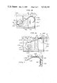
- FIG. 2 Illustrated in FIG. 2 is a cross-sectional view of a portion of the housing shown in FIG. 1 along the line 2--2.
- FIG. 3 Illustrated in FIG. 3 is a partial exploded perspective view of the electrical connector and connector mounting assembly shown in FIG. 2.
- FIG. 4 Illustrated in FIG. 4 is an enlarged partial view of the electrical connector illustrated in FIG. 3 along the line 4--4.
- FIG. 5 Illustrated in FIG. 5 is an alternate embodiment of the electrical connector shown in FIG. 2.
- FIG. 6 Illustrated in FIG. 6 is an additional embodiment of the electrical connector illustrated in FIG. 2.
- FIG. 7 Illustrated in FIG. 7 is an enlarged partial view of the end portion of the electrical connector shown in FIG. 6, particularly illustrating the deformation of the electrical contact when coupling the mother board to the circuit board.
- FIG. 8 Illustrated in FIG. 8 is an additional embodiment of the housing shown in FIG. 1 wherein each electrical socket is adapted to receive a pair of circuit boards.
- FIG. 9 Illustrated in FIG. 9 is a cross sectional view of the interior of a portion of FIG. 8.
- FIG. 10 Illustrated in FIG. 10 is an alternate embodiment of the electrical connector illustrated in FIG. 9.
- FIG. 11 Illustrated in FIG. 11 is an exploded partial perspective view of the electrical connector illustrated in FIG. 10.
- FIG. 12 Illustrated in FIG. 12 is an alternate embodiment of the electrical connector illustrated in FIG. 9.
- FIG. 13 Illustrated in FIG. 13 is an exploded partial perspective view of the electrical connector illustrated in FIG. 12.
- FIG. 1 Illustrated in FIG. 1 is a partial perspective view of a housing adapted to received printed circuit boards. Illustrated in FIG. 2 is a cross sectional view of a portion of FIG. 1 along the lines 2--2, while illustrated in FIG. 3 is an exploded perspective view of the connector assembly for electrically coupling the circuit board to the mother board.
- the housing generally designated by numeral 20, comprises a mother board 22 which typically has self-contained circuitry and is typically fabricated from a nonconductive material.
- the mother board 22 has typically a plurality of electrical terminals 23, only one of which is shown.
- Connector mounting assemblies 24 are mounted in spaced relationship on the mother board 22 forming a plurality of electrical sockets 26 which are adapted to receive the edge portions 29 of the circuit boards 30.
- Each circuit board 30 at its edge portion 29 incorporates a plurality of electrical terminals 33 (only one of which is shown). It should be noted that a particular circuit board or mother board could have only one or a multiplicity of electrical terminals.
- the electrical terminals 23 and 33 are at substantially right angles to each other.
- the electrical terminals 23 and 33 are essentially electrically conductive metal strips rising above the boards approximately 0.004 inch. The spacing there beween is as compact as technically possibly.
- the electrical terminal 23 and 33 are connected on their underside to internal wiring (not shown). Thus, the interior of the boards are sealed from moisture or other contamination.
- the connector mounting assemblies 24 each incorporate a guide channel 36 for guiding an electrical connector 38.
- the electrical connector 38 comprises a spring member 40 having a first end 41 terminating in a curved end, in this case a circular tube 42.
- FIG. 4 Illustrated in FIG. 4 is an enlarged cross-sectional view of a portion of the circular tube 42 along the line 4--4.
- the tube 42 comprises an inter spring metal member 50, preferrably made of beryllium copper, with an insulation layer 52 is bonded thereto. Preferrably this insulation layer is Mylar and at least covers a portion of the tube 42. Electrical contacts 54 are attached to the insulation layer 52 which at least extend partially about the tube 42 but always insulated by the layer 52 from the member 50.
- a hollow circular shaped tube 62 mounted to the second end 60 of the spring member 40.
- a cam member 64 Rotatably mounted within the tube 62 is a cam member 64 having supporting shafts 66 (only one is shown) which are offset from the centerline 67 of the cam member 64.
- the shafts 66 are rotatably mounted in slots 70 (only one is shown) of the locking assembly 24.
- Attached to the shaft 66 is a handle 72 which protrudes out of the housing and thus is accessible from the front of the housing.
- the cam member 64 causes the tube 42 to translate guided by the channel 36 maintaining slideable contact with the terminal 23 and thereafter coming into contact with the electrical terminal 33 on the circuit board 30.
- the position of the slot 70 and channel 36 are such that the contact 54 always remains in slideable contact with the terminal 23 with a substantial spring force.
- the electrical terminals on the mother board, circuit board, and the electrical contacts on the electrical connector will be referred to in the plural but it is again noted that the number could be as low as one of course, in the vast majority of situations there will be a plurality of electrical terminals and contacts.
- FIG. 5 Illustrated in FIG. 5 is an alternate embodiment of the one shown in FIG. 2.
- the electrical connector, generally designated as numeral 80 comprises a spring member 82 terminating at its first end 84 in a curved member 86 (semicircular in shape).
- the second end 88 of the spring member 82 is coupled to a hollow cylindrical tube 90.
- Rotatably mounted within the hollow member 90 is a cam member 92.
- Mounted at each end of the cam member 92 are supporting shafts 94 (only one is shown) which are in turn rotatably mounted in the locking assembly 96.
- the curved member 86 incorporates insulated electrical contacts which slideably engages first electrical terminals 100 mounted on the mother board 102.
- the circuit board 103 also incorporates at least one second electrical terminal 106.
- Incorporated into the connector mounting assembly 96 is a flange member 112 which engages the spring member 82 and tends to force the electrical contact into slideable engagement with the electrical terminal 100.
- Rotation of the support shaft 94 causes the electrical contact 80 to slide along the first electrical terminals 100 and into engagement with the second electrical terminals 106 on the circuit board 103.
- the guide 112 ensures that such contact is made, i.e., to the position indicated by 80' (dotted lines).
- FIG. 6 Illustrated in FIG. 6 is another alternate embodiment to that shown in FIG. 1-4.
- the electrical connector generally designated by numeral 118
- the second end 120 of the spring member 122 is fastened directly to the cam member 124 by fastener 125 (only one is shown).
- the support shaft 126 offset from the centerline 127 of the cam member 124
- rotation thereof causes the curved member 130 at the first end 132 of the spring member 122 to move to the position indicated by numeral 122' (dotted lines) and engage the electrical terminals 140 on the circuit board 142 while maintaining slideable engagement with the electrical terminals 144 on the mother board 146.
- a guide member 150 mounted to the connector mounting assembly 152 ensures that the electrical contacts 130 always remains in contact with terminals 144 and is driven into contact with terminals 140 with a great degree of force.
- FIG. 7 Illustrated in FIG. 7 is an enlarged view of the curved member 132 of the spring member 122 showing contacts 130 engaged with the terminals 144 of the mother board 146 and terminal 140 of the circuit board 142.
- the large distortion will cause a wiping action on both terminals ensuring that any oxide or contamination is wiped these said terminals producing a sound electrical connection between the two.
- FIG. 8 Illustrated in FIG. 8 is a side elevation view of an alternate embodiment of the housing illustrated in FIG. 1.
- the housing generally designated by numeral 160, comprises a mother board 162 to which are mounted a plurality of connector mounting assemblies 163 having a socket 164 adapted to receive a circuit board assembly 165.
- Circuit board assembly 165 has two circuit boards 166 and 167 in spaced relationship having edge portions 168 and 169, respectively, mounted in the socket 164.
- the mother board is provided with protrusions 170 which act as guides for the circuit board assembly 165.
- FIG. 9 Illustrated in FIG. 9 is a cross sectional view of the interior of the connector mounting assembly 163. Referring to both FIGS. 8 and 9 it can be seen that the circuit boards 166 and 167 are mounted in the socket 164.
- An electrical connector, generally indicated by numeral 172, is mounted between the circuit boards and comprises a pair of spring members 174, 174' having their first ends terminating in curved members 176, 176', respectively, having electrical contacts mounted thereon in a manner similar to the electrical connector 82 illustrated in FIG. 5.
- the spring members 174 and 174' at their second ends 180 and 180', respectively, are joined together.
- At the center of the electrical connector 172 are a plurality of holes 182 (only one of which is shown).
- a cam member 200 is rotatably mounted to the locking assembly via shafts 202 (only one of which is shown).
- the cam member 200 incorporates a plurality of grooves 204 in alignment with the plurality of holes 182 and, thus, the pin 190 extends into these grooves. This ensures that the electrical connector 172 is properly located in relationship to the circuit boards. Rotation of the cam 200 forces the electrical connector to the position indicated by 172' causing the electrical contacts into engagement with the electrical terminals 206 and 206' on the circuit boards 166 and 167 while still maintaining slideable contact with the electrical terminals 208 and 208', respectively, on the mother board 162.
- a pair of circuit boards can be simultaneously secured in and electrically connected the housing.
- FIG. 10 Illustrated in FIG. 10 is a cross-sectional view similar to that shown in FIG. 9 disclosing a different embodiment of an electrical connector.
- FIG. 11 Illustrated in FIG. 11 is a partial exploded perspective view of a diifferent embodiment of the electrical connector 172 shown in FIG. 9.
- the electrical connector generally designated by numeral 228 comprising a pair of spring members 230 and 230'.
- the spring member 230 and 230' which have first ends terminating in curved members 232 and 232', respectively.
- These curved members 232 and 232' are similar to those disclosed in FIG.
- FIG. 12 Illustrated in FIG. 12 is a cross sectional view of another embodiment of the electrical connector mounted within a connector mounting assembly. Illustrated in FIG. 13 is a partial exploded perspective view of the embodiment illustrated in FIG. 12.
- the locking assembly 270 contains an electrical connector 272, generally designated by numeral 272, having first and second spring members 274 and 274'.
- circular tubes 278 and 278' which are identical to the one shown in FIG. 2, i.e., circular tube 42 of the electrical connector 38.
- the second ends 280 and 280' of the spring members 274 and 274', respectively, are coupled together and joined to a tubular member 282.
- a tubular member 282 Rotatably mounted within the tubular member 282 is a cam member 284 having an axis of rotation indicated by numeral 286.
- a pair of shafts 288 (only one of which is shown) are mounted on the end of the cam member 284 offset from the axis of rotation 286 of the cam member.
- the front panel operated zero inseration force housing for circuit boards and the electrical connector therefor has application on electronic system and subsystems.
Landscapes
- Coupling Device And Connection With Printed Circuit (AREA)
Abstract
Description
Claims (34)
Priority Applications (1)
| Application Number | Priority Date | Filing Date | Title |
|---|---|---|---|
| US06/521,802 US4518210A (en) | 1983-08-10 | 1983-08-10 | Zero-insertion-force housing for circuit boards |
Applications Claiming Priority (1)
| Application Number | Priority Date | Filing Date | Title |
|---|---|---|---|
| US06/521,802 US4518210A (en) | 1983-08-10 | 1983-08-10 | Zero-insertion-force housing for circuit boards |
Publications (1)
| Publication Number | Publication Date |
|---|---|
| US4518210A true US4518210A (en) | 1985-05-21 |
Family
ID=24078230
Family Applications (1)
| Application Number | Title | Priority Date | Filing Date |
|---|---|---|---|
| US06/521,802 Expired - Lifetime US4518210A (en) | 1983-08-10 | 1983-08-10 | Zero-insertion-force housing for circuit boards |
Country Status (1)
| Country | Link |
|---|---|
| US (1) | US4518210A (en) |
Cited By (27)
| Publication number | Priority date | Publication date | Assignee | Title |
|---|---|---|---|---|
| US4603928A (en) * | 1985-03-20 | 1986-08-05 | Amp Incorporated | Board to board edge connector |
| US4773873A (en) * | 1986-10-01 | 1988-09-27 | Thinking Machines Corporation | Bistable zero insertion force connector |
| US4840569A (en) * | 1988-06-27 | 1989-06-20 | Itt Corporation | High density rotary connector |
| US4846699A (en) * | 1987-12-02 | 1989-07-11 | Amp Incorporated | Power connector system for daughter cards in card cages |
| US4881901A (en) * | 1988-09-20 | 1989-11-21 | Augat Inc. | High density backplane connector |
| US5102342A (en) * | 1989-11-13 | 1992-04-07 | Augat Inc. | Modified high density backplane connector |
| USRE34190E (en) * | 1986-05-27 | 1993-03-09 | Rogers Corporation | Connector arrangement |
| US5205739A (en) * | 1989-11-13 | 1993-04-27 | Augat Inc. | High density parallel interconnect |
| US6530279B1 (en) * | 2002-03-07 | 2003-03-11 | Screening Systems, Inc. | Fixture for holding electronic components for vibration testing |
| US20100093195A1 (en) * | 2008-10-13 | 2010-04-15 | Tyco Electronics Corporation | Connector assembly having multiple contact arrangements |
| US20100093189A1 (en) * | 2008-10-13 | 2010-04-15 | Tyco Electronics Corporation | Connector assembly having signal and coaxial contacts |
| US7740489B2 (en) | 2008-10-13 | 2010-06-22 | Tyco Electronics Corporation | Connector assembly having a compressive coupling member |
| US7771207B2 (en) | 2008-09-29 | 2010-08-10 | Tyco Electronics Corporation | Assembly for interconnecting circuit boards |
| US7789669B1 (en) | 2009-04-23 | 2010-09-07 | Tyco Electronics Corporation | Removable card connector assemblies having flexible circuits |
| US7789668B1 (en) | 2009-04-23 | 2010-09-07 | Tyco Electronics Corporation | Connector assemblies and systems including flexible circuits |
| US7794233B1 (en) | 2009-06-09 | 2010-09-14 | Tyco Electronics Corporation | Flexible circuit member for electrically coupling connectors with one another |
| US20100303415A1 (en) * | 2009-04-23 | 2010-12-02 | Tyco Electronics Corporation | Connector assemblies and systems including flexible circuits |
| US20110151687A1 (en) * | 2009-12-18 | 2011-06-23 | Tyco Electronics Corporation | Interconnect assembly having a separable mating interface |
| US20110151685A1 (en) * | 2009-12-23 | 2011-06-23 | Tyco Electronics Corporation | Connector assembly for coupling circuit boards |
| US20110170827A1 (en) * | 2010-01-13 | 2011-07-14 | Tyco Electronics Corporation | Connectors and assemblies having a plurality of moveable mating arrays |
| US20110171848A1 (en) * | 2010-01-11 | 2011-07-14 | Tyco Electronics Corporation | Linearly actuated connector mating interface |
| US8251755B2 (en) | 2010-06-14 | 2012-08-28 | Tyco Electronics Corporation | Connector with a laterally moving contact |
| US8282422B2 (en) | 2009-11-24 | 2012-10-09 | Tyco Electronics Corporation | Electrical connector assembly having a separable mating interface |
| US8282290B2 (en) | 2010-01-13 | 2012-10-09 | Tyco Electronics Corporation | Connectors and assemblies having a plurality of moveable mating arrays |
| US8292644B2 (en) | 2010-04-09 | 2012-10-23 | Tyco Electronics Corporation | Connector assembly having a floating mating array |
| US8328571B2 (en) | 2010-11-04 | 2012-12-11 | Tyco Electronics Corporation | Connector assemblies having moveable mating arrays and power connectors |
| US8342866B2 (en) | 2010-11-04 | 2013-01-01 | Tyco Electronics Corporation | Connector assemblies having mating sides moved by fluidic coupling mechanisms |
Citations (7)
| Publication number | Priority date | Publication date | Assignee | Title |
|---|---|---|---|---|
| US3129990A (en) * | 1960-12-01 | 1964-04-21 | Ibm | Circuit board assembly |
| US3173732A (en) * | 1962-02-09 | 1965-03-16 | Brown Engineering Company Inc | Printed circuit board connector |
| US3609463A (en) * | 1968-10-01 | 1971-09-28 | Bull General Electric | Connectors for printed-circuit cards |
| US3858958A (en) * | 1972-10-31 | 1975-01-07 | Int Computers Ltd | Methods and apparatus for forming electrical connections |
| US3920030A (en) * | 1974-10-18 | 1975-11-18 | Made Inc | Device for cleaning and sterilizing artificial kidneys |
| US4386815A (en) * | 1981-04-08 | 1983-06-07 | Amp Incorporated | Connector assembly for mounting a module on a circuit board or the like |
| US4451818A (en) * | 1982-07-06 | 1984-05-29 | Amp Incorporated | Miniature connector for a circuit board edge |
-
1983
- 1983-08-10 US US06/521,802 patent/US4518210A/en not_active Expired - Lifetime
Patent Citations (7)
| Publication number | Priority date | Publication date | Assignee | Title |
|---|---|---|---|---|
| US3129990A (en) * | 1960-12-01 | 1964-04-21 | Ibm | Circuit board assembly |
| US3173732A (en) * | 1962-02-09 | 1965-03-16 | Brown Engineering Company Inc | Printed circuit board connector |
| US3609463A (en) * | 1968-10-01 | 1971-09-28 | Bull General Electric | Connectors for printed-circuit cards |
| US3858958A (en) * | 1972-10-31 | 1975-01-07 | Int Computers Ltd | Methods and apparatus for forming electrical connections |
| US3920030A (en) * | 1974-10-18 | 1975-11-18 | Made Inc | Device for cleaning and sterilizing artificial kidneys |
| US4386815A (en) * | 1981-04-08 | 1983-06-07 | Amp Incorporated | Connector assembly for mounting a module on a circuit board or the like |
| US4451818A (en) * | 1982-07-06 | 1984-05-29 | Amp Incorporated | Miniature connector for a circuit board edge |
Cited By (36)
| Publication number | Priority date | Publication date | Assignee | Title |
|---|---|---|---|---|
| US4603928A (en) * | 1985-03-20 | 1986-08-05 | Amp Incorporated | Board to board edge connector |
| USRE34190E (en) * | 1986-05-27 | 1993-03-09 | Rogers Corporation | Connector arrangement |
| US4773873A (en) * | 1986-10-01 | 1988-09-27 | Thinking Machines Corporation | Bistable zero insertion force connector |
| US4846699A (en) * | 1987-12-02 | 1989-07-11 | Amp Incorporated | Power connector system for daughter cards in card cages |
| US4840569A (en) * | 1988-06-27 | 1989-06-20 | Itt Corporation | High density rotary connector |
| US4881901A (en) * | 1988-09-20 | 1989-11-21 | Augat Inc. | High density backplane connector |
| US5102342A (en) * | 1989-11-13 | 1992-04-07 | Augat Inc. | Modified high density backplane connector |
| US5205739A (en) * | 1989-11-13 | 1993-04-27 | Augat Inc. | High density parallel interconnect |
| US6530279B1 (en) * | 2002-03-07 | 2003-03-11 | Screening Systems, Inc. | Fixture for holding electronic components for vibration testing |
| US7771207B2 (en) | 2008-09-29 | 2010-08-10 | Tyco Electronics Corporation | Assembly for interconnecting circuit boards |
| US20110021077A1 (en) * | 2008-10-13 | 2011-01-27 | Tyco Electronics Corporation | Connector assembly having multiple contact arrangements |
| US7740489B2 (en) | 2008-10-13 | 2010-06-22 | Tyco Electronics Corporation | Connector assembly having a compressive coupling member |
| US20100093189A1 (en) * | 2008-10-13 | 2010-04-15 | Tyco Electronics Corporation | Connector assembly having signal and coaxial contacts |
| US8070514B2 (en) | 2008-10-13 | 2011-12-06 | Tyco Electronics Corporation | Connector assembly having multiple contact arrangements |
| US7896698B2 (en) | 2008-10-13 | 2011-03-01 | Tyco Electronics Corporation | Connector assembly having multiple contact arrangements |
| US20100093195A1 (en) * | 2008-10-13 | 2010-04-15 | Tyco Electronics Corporation | Connector assembly having multiple contact arrangements |
| US7867032B2 (en) | 2008-10-13 | 2011-01-11 | Tyco Electronics Corporation | Connector assembly having signal and coaxial contacts |
| US20100303415A1 (en) * | 2009-04-23 | 2010-12-02 | Tyco Electronics Corporation | Connector assemblies and systems including flexible circuits |
| US7789668B1 (en) | 2009-04-23 | 2010-09-07 | Tyco Electronics Corporation | Connector assemblies and systems including flexible circuits |
| US8113851B2 (en) | 2009-04-23 | 2012-02-14 | Tyco Electronics Corporation | Connector assemblies and systems including flexible circuits |
| US7789669B1 (en) | 2009-04-23 | 2010-09-07 | Tyco Electronics Corporation | Removable card connector assemblies having flexible circuits |
| US7794233B1 (en) | 2009-06-09 | 2010-09-14 | Tyco Electronics Corporation | Flexible circuit member for electrically coupling connectors with one another |
| US8282422B2 (en) | 2009-11-24 | 2012-10-09 | Tyco Electronics Corporation | Electrical connector assembly having a separable mating interface |
| US20110151687A1 (en) * | 2009-12-18 | 2011-06-23 | Tyco Electronics Corporation | Interconnect assembly having a separable mating interface |
| US8033835B2 (en) | 2009-12-18 | 2011-10-11 | Tyco Electronics Corporation | Interconnect assembly having a separable mating interface |
| US20110151685A1 (en) * | 2009-12-23 | 2011-06-23 | Tyco Electronics Corporation | Connector assembly for coupling circuit boards |
| US8033852B2 (en) | 2009-12-23 | 2011-10-11 | Tyco Electronics Corporation | Connector assembly for coupling circuit boards |
| US20110171848A1 (en) * | 2010-01-11 | 2011-07-14 | Tyco Electronics Corporation | Linearly actuated connector mating interface |
| US8221146B2 (en) | 2010-01-11 | 2012-07-17 | Tyco Electronics Corporation | Linearly actuated connector mating interface |
| US8215964B2 (en) | 2010-01-13 | 2012-07-10 | Tyco Electronics Corporation | Connectors and assemblies having a plurality of moveable mating arrays |
| US20110170827A1 (en) * | 2010-01-13 | 2011-07-14 | Tyco Electronics Corporation | Connectors and assemblies having a plurality of moveable mating arrays |
| US8282290B2 (en) | 2010-01-13 | 2012-10-09 | Tyco Electronics Corporation | Connectors and assemblies having a plurality of moveable mating arrays |
| US8292644B2 (en) | 2010-04-09 | 2012-10-23 | Tyco Electronics Corporation | Connector assembly having a floating mating array |
| US8251755B2 (en) | 2010-06-14 | 2012-08-28 | Tyco Electronics Corporation | Connector with a laterally moving contact |
| US8328571B2 (en) | 2010-11-04 | 2012-12-11 | Tyco Electronics Corporation | Connector assemblies having moveable mating arrays and power connectors |
| US8342866B2 (en) | 2010-11-04 | 2013-01-01 | Tyco Electronics Corporation | Connector assemblies having mating sides moved by fluidic coupling mechanisms |
Similar Documents
| Publication | Publication Date | Title |
|---|---|---|
| US4518210A (en) | Zero-insertion-force housing for circuit boards | |
| US4517625A (en) | Circuit board housing with zero insertion force connector | |
| USRE36845E (en) | High density, high bandwidth, coaxial cable, flexible circuit and circuit board connection assembly | |
| US4571014A (en) | High frequency modular connector | |
| US5228864A (en) | Connectors with ground structure | |
| US4451107A (en) | High speed modular connector for printed circuit boards | |
| US6494734B1 (en) | High density electrical connector assembly | |
| US6042394A (en) | Right-angle connector | |
| EP0632933B1 (en) | A miniaturized high-density coaxial connector system with staggered grouper modules | |
| EP0458884B1 (en) | Shielded right angled header | |
| US3745509A (en) | High density electrical connector | |
| US4418972A (en) | Electrical connector for printed wiring board | |
| US5479320A (en) | Board-to-board connector including an insulative spacer having a conducting surface and U-shaped contacts | |
| US5244395A (en) | Circuit interconnect system | |
| US4838800A (en) | High density interconnect system | |
| EP1023747B1 (en) | Connector system | |
| KR20020061122A (en) | High speed, high density interconnect system for differential and single-ended transmission applications | |
| US4834660A (en) | Flexible zero insertion force interconnector between circuit boards | |
| US6918775B2 (en) | Method for interconnecting multiple printed circuit boards | |
| US5158470A (en) | Solderless system for retention and connection of a contact with a plastic circuit element | |
| US5261829A (en) | Connectors with ground structure | |
| USRE32691E (en) | High speed modular connector for printed circuit boards | |
| JP2002373717A (en) | Printed circuit interface for i/o connector | |
| EP0418045B1 (en) | Coaxial pin connector having an array of conductive hollow cylindrical structures | |
| US5259772A (en) | Connectors with ground structure |
Legal Events
| Date | Code | Title | Description |
|---|---|---|---|
| AS | Assignment |
Owner name: LOCKHEED CORPORATION BURBANK, CA Free format text: ASSIGNMENT OF ASSIGNORS INTEREST.;ASSIGNOR:MORRISON, ROBERT A.;REEL/FRAME:004165/0335 Effective date: 19830805 |
|
| STCF | Information on status: patent grant |
Free format text: PATENTED CASE |
|
| FEPP | Fee payment procedure |
Free format text: PAYOR NUMBER ASSIGNED (ORIGINAL EVENT CODE: ASPN); ENTITY STATUS OF PATENT OWNER: LARGE ENTITY |
|
| FPAY | Fee payment |
Year of fee payment: 4 |
|
| FPAY | Fee payment |
Year of fee payment: 8 |
|
| FPAY | Fee payment |
Year of fee payment: 12 |
|
| AS | Assignment |
Owner name: LOCKHEED MARTIN CORPORATION, MARYLAND Free format text: MERGER;ASSIGNOR:LOCKHEED CORPORATION;REEL/FRAME:009430/0915 Effective date: 19960128 |