US4494041A - Incandescent ballast assembly - Google Patents
Incandescent ballast assembly Download PDFInfo
- Publication number
- US4494041A US4494041A US06/463,226 US46322683A US4494041A US 4494041 A US4494041 A US 4494041A US 46322683 A US46322683 A US 46322683A US 4494041 A US4494041 A US 4494041A
- Authority
- US
- United States
- Prior art keywords
- incandescent
- fluorescent lamp
- lamp
- ballast assembly
- filament
- Prior art date
- Legal status (The legal status is an assumption and is not a legal conclusion. Google has not performed a legal analysis and makes no representation as to the accuracy of the status listed.)
- Expired - Fee Related
Links
Images

Classifications
-
- H—ELECTRICITY
- H01—ELECTRIC ELEMENTS
- H01J—ELECTRIC DISCHARGE TUBES OR DISCHARGE LAMPS
- H01J61/00—Gas-discharge or vapour-discharge lamps
- H01J61/02—Details
- H01J61/54—Igniting arrangements, e.g. promoting ionisation for starting
- H01J61/541—Igniting arrangements, e.g. promoting ionisation for starting using a bimetal switch
- H01J61/544—Igniting arrangements, e.g. promoting ionisation for starting using a bimetal switch and an auxiliary electrode outside the vessel
Definitions
- This invention relates to ballast and starting apparatus suitable for use with fluorescent lamps and more particularly to a ballast assembly of the resistance type utilizing an incandescent lamp in conjunction with a lamp starting arrangement employing a starting aid contacting the fluorescent lamp.
- choke-type ballast assembly One known approach to the problem of replacing incandescent lamps with fluorescent lamps includes the employment of a choke-type ballast assembly.
- relatively rapid changes in current with time in a choke coil or the "L di/dt" chacteristic of a choke ballast is utilized to provide a pulse potential necessary to the starting of a fluroescent lamp.
- choke coils not only are costly but also undesirably add weight which may be deleterious to the fixture already in place.
- Still another arrangement for replacing incandescent lamps with fluorescent lamps includes a resistive-type ballast arrangement wherein an incandescent lamp is utilized as the resistive element.
- an incandescent lamp is utilized as the resistive element.
- the ordinary ballast arrangement includes a glow bottle shunted across the fluorescent lamp filaments and an incandescent lamp coupling one of the filaments to the voltage supply or source.
- the glow bottle includes the usual bimetal within a gas-containing envelope. Upon activation, the gas ionizes causing the bimetal to heat and deflect to provide a short-circuit so that current is applied to the filaments of the fluorescent lamp. Thereafter, the bimetal cools which opens the preheat circuit and the energy applied across the heated filaments is sufficient to cause ignition of the lamps.
- each of the filaments of the fluorescent lamps will have a voltage drop thereacross of about ten-volts during the preheating phase which leaves a drop of about 80% of the 120-volt supply voltage across the incandescent lamp.
- the incandescent lamp will operate at about one-half or 50% of the supply voltage.
- a resistive ballast employing an incandescent lamp presents a serious design problem. If the incandescent lamp is designed to operate at one-half or 50% of the supply voltage, the bulb would be overstressed during the preheat period since about 80% of the supply voltage would be applied to the incandescent lamp. Thus, a short life span would result.
- an incandescent lamp designed to operate at 80% of the service voltage would receive only about 50 to 60% of the service voltage during normal operation of the fluorescent lamp.
- the lumen output of the incandescent lamp would fall to about 30% of the rated value which is obviously unsatisfactory insofar as efficiency is concerned.
- Another problem associated with resistive ballast configurations is the difficulty of starting the fluorescent lamp.
- one method of inducing a starting voltage is to provide voltage spikes.
- such techniques involve added choke coils or other forms of additional apparatus which undesirably add to the cost and complexity of the apparatus.
- Other techniques include the utilization of an electrically floating conductive stripe within or affixed to the outer surface of the fluorescent lamp envelope.
- the known structures require a relatively high supply voltage in order to effect the capability for starting a fluorescent lamp. Since the starting voltages are limited to the 120-volt supply voltages, increased high voltage is not an alternative..
- An object of the present invention is to provide an enhanced ballast assembly for a fluorescent lamp. Another object of the invention is to improve the starting capability of a fluorescent lamp arrangement. Still another object of the invention is to provide an economical and energy efficient ballast assembly for a fluorescent lamp.
- an incandescent ballast assembly for a fluorescent lamp wherein the fluorescent lamp is shunted by a series connected starter and unidirectional conduction device and a pair of terminals formed for connection to a potential source having one terminal connected by an incandescent lamp to one filament winding, the other terminal connects to another filament winding, and a starting aid affixed to the lamp and connected by an impedance to a junction of the incandescent lamp and a filament winding.
- potential available at a potential source is applied to the bulb of the fluorescent lamp by way of an impedance coupled to a starting aid affixed to the fluorescent lamp and tq the junction of an incandescent and a filament winding.
- the fluorescent lamp has a potential on the bulb thereof and an added applied potential of an amount sufficient to effect a field breakdown and lamp ignition.
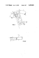
- FIG. 1 is a diagrammatic illustration of a preferred form of fluorescent lamp and incandescent ballast assembly
- FIG. 2 is an enlarged view of a starting aid connecting arrangement
- FIG. 3 is a circuit diagram illustrating the incandescent ballast and fluorescent lamp arrangement of FIG. 1.
- FIG. 1 illustrates a fluorescent lamp and accompanying incandescent ballast assembly combination.
- a fluorescent lamp 5 preferably but not necessarily of a substantially circular configuration, has a filament winding 7 and 9 at each end of an envelope 11.
- the envelope 11 has a longitudinal axis extending thereby between the filament windings 7 and 9 respectively.
- a starting aid 13 which is preferably in the form of a metallized tape, extends along the longitudinal axis between the filament windings 7 and 9.
- the starting aid 13 is preferably affixed to the inner perimeter of the envelope 11 but may be attached to a fixture (not shown) extending in an essentially parallel realtionship to the envelope 11.
- the starting aid 13 is preferably in the form of a polyester tape 15 having metallized layer 17 thereon.
- a brass strip 19, such as a piece of brass shim stock for example, is affixed to the metallized layer 17 of the polyester tape 15 to provide a high impedance connection therebetween.
- This high impedance connection about 10 6 ohm for example, serves to eliminate any potential shock hazard in the event of personal contact therewith.
- a spring loaded connector 21 of FIG. 1 couples the high impedance by way of the brass strip 19 to the junction of one filament winding 7 and an incandescent lamp 23.
- the incandescent lamp 23 couples to the filament winding 7 and the spring-loaded connector 21 to one terminal 25 of a pair of terminals 25 and 27 formed for connection to a potential source (not shown).
- the other terminal 27 of the pair of terminals 25 and 27 is directly connected to the other filament winding 9 of the fluorescent lamp 5.
- a starter means 29 and a unidirectional conduction device 31, such as a diode are series connected to the filament windings 7 and 9 of the fluorescent lamp 5.
- the starter means 29 is a glow bottle type starter having a configuration which includes either a fixed terminal with a bimetal adjacent thereto or two parallel bimetal elements whereby a polarized or nonpolarized conductivity capability is provided. If a polarized starter is used, the anode of the diode must be connected to the bimetal contact of the starter.
- the diode 31 is available from numerous sources including the Motorola Company whereat it is designated as a 200-volt, IN 4003 diode.
- the fluorescent lamp may be a well-known so-called 8-inch "Circline” lamp manufactured by General Telephone Company of Danvers, Mass., while the incandescent lamp is a 75-volt, 400 ma. lamp.
- the fluorescent lamp 5 has a longitudinal axis extending between filament windings 7 and 9 at opposite ends of an envelope 11.
- a starting aid 13 such as metallized tape, is coupled by a high impedance connector 20 to one of the filament windings 7 and to an incandescent lamp 23.
- the incandescent lamp 23 is connected to a terminal 25 formed for connection to a potential source.
- Another terminal 27 is coupled to the other filament winding 9.
- a glow starter means 29 in series connection with the diode 31 is coupled to the filament windings 7 and 9.
- a capacitor 33 shunts a glow bottle 35 to provide the glow starter 29.
- an ordinary incandescent lamp ballast arrangement results in a voltage drop across the incandescent lamp during the filament winding preheat phase which is equal to about 80% of the supply voltage. Also, such a voltage drop is excessive insofar as optimum operational voltage of the incandesent lamp is concerned and deleterious to the life span of the lamp.
- the utilization of the unidirectional conduction device or diode 31 serves to reduce this preheat voltage appearing across the incandescent lamp 23 without encountering overheating problems since the diode 31 is essentially a lossless element.
- starting of the fluorescent lamp is effected by the starting aid coupled to the service voltage source by way of a high impedance.
- a so-called "floating" starting aid which is merely affixed to the lamp envelope will raise the potential of the fluorescent lamp envelope to about one-half of the supply voltage.
- Such an envelope potential is sufficient when the supply voltage is sufficiently high.
- a relatively low supply voltage necessitates transfer of the supply potential by way of the high impedance to the envelope of the fluorescent lamp in order to provide a field strength sufficient to effect lamp ignition.
- a control circuit employing a 120-volt source potential and no diode would provide a voltage drop of about 10 volts across each of the filaments and about 100 volts across the incandescent lamp during the preheat portion of the operational cycle.
- inclusion of the above-mentioned diode causes conversion of the 120-volt supply source to about 85 volts whereby about 65 volts appear across the incandescent lamp and about 10-volts across each filament winding during the preheat portion of the operational cycle.
- about 60 volts would appear across the incandescent lamp which will provide a desired lumen output suitable for addition to the output of the fluorescent lamp.
- an incandescent ballast assembly wherein means are provided for effecting efficient operation of an incandescent ballast lamp during and after preheating of a fluorescent lamp. Additionally, means are provided for effecting a starting capability for a fluorescent lamp utilizing a relatively low service voltage source.
Landscapes
- Circuit Arrangements For Discharge Lamps (AREA)
Abstract
Description
Claims (8)
Priority Applications (1)
| Application Number | Priority Date | Filing Date | Title |
|---|---|---|---|
| US06/463,226 US4494041A (en) | 1983-02-02 | 1983-02-02 | Incandescent ballast assembly |
Applications Claiming Priority (1)
| Application Number | Priority Date | Filing Date | Title |
|---|---|---|---|
| US06/463,226 US4494041A (en) | 1983-02-02 | 1983-02-02 | Incandescent ballast assembly |
Publications (1)
| Publication Number | Publication Date |
|---|---|
| US4494041A true US4494041A (en) | 1985-01-15 |
Family
ID=23839364
Family Applications (1)
| Application Number | Title | Priority Date | Filing Date |
|---|---|---|---|
| US06/463,226 Expired - Fee Related US4494041A (en) | 1983-02-02 | 1983-02-02 | Incandescent ballast assembly |
Country Status (1)
| Country | Link |
|---|---|
| US (1) | US4494041A (en) |
Cited By (5)
| Publication number | Priority date | Publication date | Assignee | Title |
|---|---|---|---|---|
| US4649319A (en) * | 1984-10-03 | 1987-03-10 | Duro-Test Corporation | Gas discharge lamp starter |
| US5491385A (en) * | 1980-08-14 | 1996-02-13 | Nilssen; Ole K. | Instant-on screw-in fluorescent lamp |
| US6400104B1 (en) * | 2000-09-12 | 2002-06-04 | Byung Il Ham | Fluorescent lamp assembly with nightlight |
| US6661177B2 (en) * | 2000-08-08 | 2003-12-09 | Koninklijke Philips Electronics N.V. | High-pressure discharge lamp with ignition circuit including halogen incandescent lamp |
| US20070035253A1 (en) * | 2003-10-02 | 2007-02-15 | Koninklijke Philips Electronics N.V. | Tanning apparatus |
Citations (4)
| Publication number | Priority date | Publication date | Assignee | Title |
|---|---|---|---|---|
| US4268780A (en) * | 1980-03-28 | 1981-05-19 | Gte Products Corporation | Integrated fluorescent-incandescent lamp assembly |
| US4297616A (en) * | 1980-03-17 | 1981-10-27 | Xerox Corporation | Fluorescent lamp with incandescent ballasting systems |
| US4350929A (en) * | 1978-12-06 | 1982-09-21 | Moriyama Sangyo Kabushiki Kaisha | Fluorescent lighting device |
| US4358710A (en) * | 1980-12-19 | 1982-11-09 | General Electric Company | Fluorescent light unit with dimmable light level |
-
1983
- 1983-02-02 US US06/463,226 patent/US4494041A/en not_active Expired - Fee Related
Patent Citations (4)
| Publication number | Priority date | Publication date | Assignee | Title |
|---|---|---|---|---|
| US4350929A (en) * | 1978-12-06 | 1982-09-21 | Moriyama Sangyo Kabushiki Kaisha | Fluorescent lighting device |
| US4297616A (en) * | 1980-03-17 | 1981-10-27 | Xerox Corporation | Fluorescent lamp with incandescent ballasting systems |
| US4268780A (en) * | 1980-03-28 | 1981-05-19 | Gte Products Corporation | Integrated fluorescent-incandescent lamp assembly |
| US4358710A (en) * | 1980-12-19 | 1982-11-09 | General Electric Company | Fluorescent light unit with dimmable light level |
Cited By (6)
| Publication number | Priority date | Publication date | Assignee | Title |
|---|---|---|---|---|
| US5491385A (en) * | 1980-08-14 | 1996-02-13 | Nilssen; Ole K. | Instant-on screw-in fluorescent lamp |
| US4649319A (en) * | 1984-10-03 | 1987-03-10 | Duro-Test Corporation | Gas discharge lamp starter |
| US6661177B2 (en) * | 2000-08-08 | 2003-12-09 | Koninklijke Philips Electronics N.V. | High-pressure discharge lamp with ignition circuit including halogen incandescent lamp |
| US6400104B1 (en) * | 2000-09-12 | 2002-06-04 | Byung Il Ham | Fluorescent lamp assembly with nightlight |
| US20070035253A1 (en) * | 2003-10-02 | 2007-02-15 | Koninklijke Philips Electronics N.V. | Tanning apparatus |
| US7641678B2 (en) * | 2003-10-02 | 2010-01-05 | Koninklijke Philips Electronics N.V. | Tanning apparatus |
Similar Documents
| Publication | Publication Date | Title |
|---|---|---|
| US5483125A (en) | Ballast circuit for a gas discharge lamp having a cathode pre-heat arrangement | |
| US4145638A (en) | Discharge lamp lighting system using series connected starters | |
| US3573544A (en) | A gas discharge lamp circuit employing a transistorized oscillator | |
| US4163176A (en) | Energy saving fluorescent lamp | |
| US6459204B1 (en) | Dual-element 3-way compact fluorescent lamp | |
| US4268780A (en) | Integrated fluorescent-incandescent lamp assembly | |
| US4256993A (en) | Energy saving device for rapid-start fluorescent lamp system | |
| US4494041A (en) | Incandescent ballast assembly | |
| US5289084A (en) | Lamp arrangement employing a resonant circuit formed from an autotransformer and a capacitor where the capacitor is switched out of the resonant circuit and into a power factor correcting circuit when the ignition of the lamp is sensed | |
| US4613792A (en) | Symmetrical load power reduction device for lighting fixtures | |
| US4508993A (en) | Fluorescent lamp without ballast | |
| US4562381A (en) | Starting circuit for multiple fluorescent lamps | |
| US5021714A (en) | Circuit for starting and operating fluorescent lamps | |
| US5177407A (en) | Glow discharge lamp having dual anodes and circuit for operating same | |
| US4004184A (en) | Apparatus for operating gaseous discharge lamps on direct current from a source of alternating current | |
| US4958102A (en) | Three way gas discharge lamp | |
| US4654560A (en) | Three (3)-way lamp having a tungsten halogen inner envelope | |
| US5087861A (en) | Discharge lamp life and lamp lumen life-extender module, circuitry, and methodology | |
| US4748368A (en) | Three way gas discharge lamp | |
| KR970001423B1 (en) | Fluorescent lamp high frequency operating circuit | |
| US4419607A (en) | Discharge lamp starter and starting and operating circuitry | |
| US4143302A (en) | Energizing circuit for a fluorescent lamp | |
| US6417630B1 (en) | Circuit arrangement | |
| US4609849A (en) | High pressure sodium vapor lamp having D.C. resistive ballast circuits | |
| US4489255A (en) | Discharge lamp starter and starting and operating circuitry |
Legal Events
| Date | Code | Title | Description |
|---|---|---|---|
| AS | Assignment |
Owner name: GTE PRODUCTS CORPORATION A CORP. OF DE Free format text: ASSIGNMENT OF ASSIGNORS INTEREST.;ASSIGNORS:ROCHE, WILLIAM J.;ANDERSON, JOHN W. JR.;REEL/FRAME:004093/0697 Effective date: 19830119 Owner name: GTE PRODUCTS CORPORATION A CORP. OF DE, DELAWARE Free format text: ASSIGNMENT OF ASSIGNORS INTEREST;ASSIGNORS:ROCHE, WILLIAM J.;ANDERSON, JOHN W. JR.;REEL/FRAME:004093/0697 Effective date: 19830119 |
|
| FPAY | Fee payment |
Year of fee payment: 4 |
|
| FEPP | Fee payment procedure |
Free format text: PAYOR NUMBER ASSIGNED (ORIGINAL EVENT CODE: ASPN); ENTITY STATUS OF PATENT OWNER: LARGE ENTITY |
|
| FPAY | Fee payment |
Year of fee payment: 8 |
|
| REMI | Maintenance fee reminder mailed | ||
| LAPS | Lapse for failure to pay maintenance fees | ||
| FP | Lapsed due to failure to pay maintenance fee |
Effective date: 19970115 |
|
| FEPP | Fee payment procedure |
Free format text: PAYER NUMBER DE-ASSIGNED (ORIGINAL EVENT CODE: RMPN); ENTITY STATUS OF PATENT OWNER: LARGE ENTITY Free format text: PAYOR NUMBER ASSIGNED (ORIGINAL EVENT CODE: ASPN); ENTITY STATUS OF PATENT OWNER: LARGE ENTITY |
|
| STCH | Information on status: patent discontinuation |
Free format text: PATENT EXPIRED DUE TO NONPAYMENT OF MAINTENANCE FEES UNDER 37 CFR 1.362 |