US4474483A - Hydrostatic bearing apparatus with a cooling function - Google Patents
Hydrostatic bearing apparatus with a cooling function Download PDFInfo
- Publication number
- US4474483A US4474483A US06/475,644 US47564483A US4474483A US 4474483 A US4474483 A US 4474483A US 47564483 A US47564483 A US 47564483A US 4474483 A US4474483 A US 4474483A
- Authority
- US
- United States
- Prior art keywords
- fluid
- holes
- bearing bushing
- bearing
- pressurized fluid
- Prior art date
- Legal status (The legal status is an assumption and is not a legal conclusion. Google has not performed a legal analysis and makes no representation as to the accuracy of the status listed.)
- Expired - Fee Related
Links
Images


Classifications
-
- F—MECHANICAL ENGINEERING; LIGHTING; HEATING; WEAPONS; BLASTING
- F16—ENGINEERING ELEMENTS AND UNITS; GENERAL MEASURES FOR PRODUCING AND MAINTAINING EFFECTIVE FUNCTIONING OF MACHINES OR INSTALLATIONS; THERMAL INSULATION IN GENERAL
- F16C—SHAFTS; FLEXIBLE SHAFTS; ELEMENTS OR CRANKSHAFT MECHANISMS; ROTARY BODIES OTHER THAN GEARING ELEMENTS; BEARINGS
- F16C32/00—Bearings not otherwise provided for
- F16C32/06—Bearings not otherwise provided for with moving member supported by a fluid cushion formed, at least to a large extent, otherwise than by movement of the shaft, e.g. hydrostatic air-cushion bearings
- F16C32/0629—Bearings not otherwise provided for with moving member supported by a fluid cushion formed, at least to a large extent, otherwise than by movement of the shaft, e.g. hydrostatic air-cushion bearings supported by a liquid cushion, e.g. oil cushion
- F16C32/064—Bearings not otherwise provided for with moving member supported by a fluid cushion formed, at least to a large extent, otherwise than by movement of the shaft, e.g. hydrostatic air-cushion bearings supported by a liquid cushion, e.g. oil cushion the liquid being supplied under pressure
- F16C32/0651—Details of the bearing area per se
- F16C32/0659—Details of the bearing area per se of pockets or grooves
-
- F—MECHANICAL ENGINEERING; LIGHTING; HEATING; WEAPONS; BLASTING
- F16—ENGINEERING ELEMENTS AND UNITS; GENERAL MEASURES FOR PRODUCING AND MAINTAINING EFFECTIVE FUNCTIONING OF MACHINES OR INSTALLATIONS; THERMAL INSULATION IN GENERAL
- F16C—SHAFTS; FLEXIBLE SHAFTS; ELEMENTS OR CRANKSHAFT MECHANISMS; ROTARY BODIES OTHER THAN GEARING ELEMENTS; BEARINGS
- F16C32/00—Bearings not otherwise provided for
- F16C32/06—Bearings not otherwise provided for with moving member supported by a fluid cushion formed, at least to a large extent, otherwise than by movement of the shaft, e.g. hydrostatic air-cushion bearings
- F16C32/0629—Bearings not otherwise provided for with moving member supported by a fluid cushion formed, at least to a large extent, otherwise than by movement of the shaft, e.g. hydrostatic air-cushion bearings supported by a liquid cushion, e.g. oil cushion
- F16C32/064—Bearings not otherwise provided for with moving member supported by a fluid cushion formed, at least to a large extent, otherwise than by movement of the shaft, e.g. hydrostatic air-cushion bearings supported by a liquid cushion, e.g. oil cushion the liquid being supplied under pressure
-
- F—MECHANICAL ENGINEERING; LIGHTING; HEATING; WEAPONS; BLASTING
- F16—ENGINEERING ELEMENTS AND UNITS; GENERAL MEASURES FOR PRODUCING AND MAINTAINING EFFECTIVE FUNCTIONING OF MACHINES OR INSTALLATIONS; THERMAL INSULATION IN GENERAL
- F16C—SHAFTS; FLEXIBLE SHAFTS; ELEMENTS OR CRANKSHAFT MECHANISMS; ROTARY BODIES OTHER THAN GEARING ELEMENTS; BEARINGS
- F16C32/00—Bearings not otherwise provided for
- F16C32/06—Bearings not otherwise provided for with moving member supported by a fluid cushion formed, at least to a large extent, otherwise than by movement of the shaft, e.g. hydrostatic air-cushion bearings
- F16C32/0681—Construction or mounting aspects of hydrostatic bearings, for exclusively rotary movement, related to the direction of load
- F16C32/0685—Construction or mounting aspects of hydrostatic bearings, for exclusively rotary movement, related to the direction of load for radial load only
-
- F—MECHANICAL ENGINEERING; LIGHTING; HEATING; WEAPONS; BLASTING
- F16—ENGINEERING ELEMENTS AND UNITS; GENERAL MEASURES FOR PRODUCING AND MAINTAINING EFFECTIVE FUNCTIONING OF MACHINES OR INSTALLATIONS; THERMAL INSULATION IN GENERAL
- F16C—SHAFTS; FLEXIBLE SHAFTS; ELEMENTS OR CRANKSHAFT MECHANISMS; ROTARY BODIES OTHER THAN GEARING ELEMENTS; BEARINGS
- F16C37/00—Cooling of bearings
- F16C37/002—Cooling of bearings of fluid bearings
Definitions
- the present invention relates to a hydrostatic bearing apparatus for rotatably supporting a spindle by means of hydrostatic pressure generated in fluid pockets formed at an internal surface of a bearing bushing.
- pressurized fluid is supplied via respective throttle elements to fluid pockets which are circumferentially formed at an internal surface of a bearing bushing, and a spindle received in the bearing bushing is rotatably carried by means of hydrostatic pressure generated in each of the fluid pockets.
- the rotation of the spindle causes pressurized fluid in each fluid pocket to circumferentially flow as a result of being involved by the outer circumferential surface of the spindle.
- heated pressurized fluid in each fluid pocket flows therefrom into another fluid pocket next thereto at the downstream side in the rotational direction of the spindle.
- This phenomenon is called “carry-over”.
- the "carry-over” phenomenon takes place not only in a hydrostatic bearing which has no exhaust groove between every two circumferentially successive fluid pockets, but also in another hydrostatic bearing which has an exhaust groove between every two circumferentially successive fluid pockets.
- the exhaust groove is filled with heated fluid which overflows a fluid pocket located at the upstream side in the spindle rotational direction.
- the rotation of the spindle thus causes the heated fluid to flow from each fluid pocket to another fluid pocket next thereto at the downstream side of the spindle rotational direction.
- the pocket-to-pocket flow of the heated fluid is repeated, whereby the generation of heat is facilitated.
- the fluid pockets are supplied with pressurized fluid through respective throttle elements. Pressure loss caused by the throttle elements is converted into thermal energy. In addition, rotation of the spindle is accompanied by fluid friction, which results in heat generation.
- the temperature of the bearing hardly increases since heated pressurized fluid is completely discharged from the fluid pockets outside the bearing and after cooled off by a cooler device, is supplied again from a fluid pump to the fluid pockets.
- pressurized fluid once heated by experiencing the "carry-over” flow is again heated in another fluid pocket to expedite an temperature increase at the fluid pocket even where thermally controlled fresh fluid is supplied to the fluid pockets.
- a known fluid bearing is provided in a bearing housing thereof with a water jacket designed to diminish the temperature increase of a bearing bushing thereof.
- the provision of the water jacket is not effective to prevent heat generation at the internal surface of the bearing bushing and raises a difficulty in designing down-sized hydrostatic bearings.
- Another object of the present invention is to provide an improved hydrostatic bearing apparatus wherein heated fluid discharged from each fluid pocket is prevented from flowing into another fluid pocket circumferentially next thereto, so that accelerative heat generation caused by the repetition of pocket-to-pocket flow of heated fluid can be avoided.
- Another object of the present invention is to provide an improved hydrostatic bearing apparatus wherein the carry-over flow of heated fluid from each fluid pocket to another fluid pocket circumferentialy next thereto is prevented by positively permitting the carry-over flow of cooled fluid into the latter fluid pocket.
- a further object of the present invention is to provide an improved hydrostatic bearing apparatus wherein heat exchange is carried out in the vicinity of a heat generating area.
- a still further object of the present invention is to provide an improved hydrostatic bearing apparatus incorporating a heat exchange arrangement which is effective to restrain temperature increase of a bearing bushing thereof and which does not impose substantial limitation on designing the hydrostatic bearing apparatus to a small size.
- a hydrostatic bearing apparatus which comprises a bearing housing, a bearing bushing mounted in the bearing housing and a spindle rotatably received in an internal surface of the bearing bushing.
- the bearing bushing is formed at its internal surface with a plurality of circumferentially separate fluid pockets and a plurality of exhaust grooves each extending substantially in the axial direction of the bearing bushing and between every contiguous two of the fluid pockets.
- the bearing apparatus further comprises a first fluid supply for supplying high-pressurized fluid to the fluid pockets, a second fluid supply for supplying low-pressurized fluid to the exhaust groove, and a cooler device for cooling the low-pressurized fluid supplied to the exhaust groove.
- the cooled low-pressurized fluid When the apparatus is in operation, the cooled low-pressurized fluid is filled in, and flows through the exhaust grooves to prevent heated high-pressurized fluid from being carried over by the rotation of the spindle from one of every contiguous two fluid pockets to the other fluid pocket.
- the heated high-pressurized fluid is positively discharged with the cooled low-pressurized fluid flowing along the exhaust grooves, whereby the generation of heat at the bearing surface can be restrained.
- a part of the cooled low-pressurized fluid in the exhaust grooves is involved by the rotation of the spindle to be carried over into the fluid pockets. This advantageously results in cooling the heated high-pressurized fluid in the fluid pockets.
- a hydrostatic bearing apparatus comprises a bearing bushing formed with a plurality of axially extending through passages therein, a pair of annular cap members respectively secured to axial opposite ends of the bearing bushing and formed therein with return passages serially connecting at least a part of the through passages, and a fluid supply for supplying low-pressurized fluid to flow the same through the serially connected part of the through passages.
- a cooler device is further provided for cooling the low-pressurized fluid supplied from the fluid supply.
- FIG. 1 is a cross-sectional view of a hydrostatic bearing apparatus according to the present invention
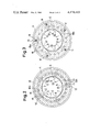
- FIG. 2 is a sectional view of the apparatus taken along the line II--II in FIG. 1;
- FIG. 3 is a sectional view of the apparatus taken along the line III--III in FIG. 1;
- FIG. 4 is a sectional view of an annular cap member taken along the line IV--IV in FIG. 1;
- FIG. 5 is a front view of another annular cap member as viewed along the line V--V in FIG. 1.
- a hydrostatic bearing apparatus having a bearing housing 1, which is formed with an upper drain port 2 and a lower drain port 3.
- a bearing bushing 4 is fixedly mounted in the bearing housing 1 and is provided with a bore, in which a spindle 5 is rotatably carried.
- An internal surface 6 of the bore is formed with a plurality of circumferentially separate fluid pockets 7 and a plurality of exhaust grooves 8. Each of the exhaust grooves 8 extends in the axial direction of the bearing bushing 4 between contiguous two of the fluid pockets 7.
- each exhaust groove 8 is in fluid communication with an annular exhaust groove 24, which is formed at the right axial end portion of the internal surface 6 to in turn communicate with the upper drain port 2 through a radial passage 2a.
- each of the exhaust grooves 8 is further formed with a fluid conduction slant surface 22 at one of upper edges thereof which is ahead of the other upper edge in the rotational direction of the spindle 5.
- the slant surface 22 extends throughout at least the entire width of the fluid pockets 7 in the axial direction of the bearing bushing 4.
- the bearing bushing 4 is formed at an outer circumferential surface thereof with a first annular inlet port 9 to receive high-pressurized fluid P1 from a first fluid supply 31.
- the annular inlet port 9 is in fluid communication with the fluid pockets 7 through respective first supply passages 10 each incorporating a throttle element 11 therein.
- the outer circumferential surface of the bearing bushing 4 is further formed with a second annular inlet port 12 to receive cooled low-pressurized fluid P2 from a second fluid supply 32 via a cooler device 33.
- the second annular inlet port 12 is in fluid communication with the exhaust grooves 8 through respective second supply passages 13.
- a flow rate control orifice may be provided in each of the second supply passages 13.
- the bearing bushing 4 is further formed therein a plurality of through holes 15, which are arranged at equiangular intervals in the circumferential direction of the bearing bushing 4 to extend in the axial direction of the bearing bushing 4.
- a pair of annular end caps 17 and 18 are respectively fitted in, and secured to cap bores formed at axial opposite ends of the bearing bushing 4.
- the annular end caps 17 and 18 are formed with a plurality of arcuate elongated holes 19 and 20 at respective inner end surfaces thereof, as best shown in FIGS. 4 and 5. These arcuate elongated holes 19 and 20 make all of the through holes 15 to communicate in series.
- one of the through holes 15 (hereafter referred to as “inlet through hole 15a") is in fluid communication with the second annular inlet port 12 through a radial passage 14, while two of the through holes 15 (hereafter referred to as "outlet through holes 15b”) which are diametrically opposed with the inlet through hole 15a are in fluid communication with the lower drain port 3.
- Communication passages 21 are further formed in the bearing bushing 4 to lead to the lower drain port 3 fluid discharged from the two outlet through holes 15b and from another annular exhaust groove 23 formed at a left end of the bearing bushing 4.
- high-pressurized fluid P1 of, e.g., 10 kg/cm 2 are supplied from the first fluid supply 31 to the first annular inlet port 9 at a flow rate of 10 l/min. and is conducted into the fluid pockets 7 via the throttle elements 11 fitted in the respective first supply passages 10. Hydrostatic pressure is thus generated in each fluid pocket 7, whereby the spindle 5 is rotatably supported without contacting the internal surface 6 of the bearing bushing 4.
- Low-pressurized fluid P2 from the second fluid supply 32 is cooled off by passing through the cooler device 33 and is supplied to the second annular inlet port 12.
- Pressurized fluid P2 from the second fluid supply 32 has a pressure of 2 or 3 kg/cm 2 and a flow rate of 10 l/min., for example, and is lower in pressure than that conducted into the fluid pockets 7.
- Cooled low-pressurized fluid P2 is conducted via the respective second supply passages 13 into the exhaust grooves 8 each located between any contiguous two of the fluid pockets 7 and flows along the exhaust grooves 8.
- Cooled low-pressurized fluid P2 is conducted into the right annular exhaust groove 24 and is discharged through the radial passage 2a and the upper exhaust port 2 into a reservoir 34 constituting a part of each of the first and second fluid supplies 31 and 32. Accordingly, the exhaust grooves 8 are normally filled with low-pressurized fluid of a low temperature. This prevents heated pressurized fluid in each fluid pocket 7 from being conveied by rotation of the spindle 5 into another fluid pocket 7 which is ahead of said fluid pocket 7 in the rotational direction of the spindle 5.
- rotation of the spindle 5 causes a part of cooled low-pressurized fluid P2 flowing along the exhaust grooves 8 to be involved into a bearing clearance between the internal surface 6 of the bearing bushing 4 and the outer circumferential surface of the spindle 5 and then, to be flown into the fluid pockets 7.
- the carry-over flow of cooled low-pressurized fluid P2 into the fluid pockets 7 advantageously results in lowering the temperature at the fluid pockets 7.
- a part of cooled low-pressurized fluid P2 supplied to the second annular inlet port 12 is conducted via the radial passage 14 into one of the through holes 15, namely into the inlet throughhole 15a.
- the fluid P2 conducted into the inlet through hole 15a is divided into two streams; one to flow through the left half of the through holes 15 in a counterclockwise direction and the other to flow through the right half of the through holes 15 in a clockwise direction, as viewed in FIG. 2.
- the two streams of cooled low-pressurized fluid P2 effect heat exchange with the bearing bushing 4, whereby the same is cooled off.
Landscapes
- Engineering & Computer Science (AREA)
- General Engineering & Computer Science (AREA)
- Mechanical Engineering (AREA)
- Magnetic Bearings And Hydrostatic Bearings (AREA)
Abstract
Description
Claims (9)
Applications Claiming Priority (4)
| Application Number | Priority Date | Filing Date | Title |
|---|---|---|---|
| JP4324882U JPS58146122U (en) | 1982-03-29 | 1982-03-29 | Hydrostatic bearing with built-in heat exchanger |
| JP57-49041 | 1982-03-29 | ||
| JP57-43248 | 1982-03-29 | ||
| JP57049041A JPS58166127A (en) | 1982-03-29 | 1982-03-29 | Static bearing with cooling function |
Publications (1)
| Publication Number | Publication Date |
|---|---|
| US4474483A true US4474483A (en) | 1984-10-02 |
Family
ID=26382997
Family Applications (1)
| Application Number | Title | Priority Date | Filing Date |
|---|---|---|---|
| US06/475,644 Expired - Fee Related US4474483A (en) | 1982-03-29 | 1983-03-15 | Hydrostatic bearing apparatus with a cooling function |
Country Status (3)
| Country | Link |
|---|---|
| US (1) | US4474483A (en) |
| EP (1) | EP0090281B1 (en) |
| DE (1) | DE3367796D1 (en) |
Cited By (30)
| Publication number | Priority date | Publication date | Assignee | Title |
|---|---|---|---|---|
| US4576488A (en) * | 1984-03-02 | 1986-03-18 | Bergische Achsenfabrik Fr. Kotz & Sohne | Bearing bushing |
| FR2582244A1 (en) * | 1985-05-22 | 1986-11-28 | Toyoda Machine Works Ltd | SPINDLE UNIT FOR A SURFACE GRINDER |
| US4699524A (en) * | 1986-05-09 | 1987-10-13 | Canadian General Electric Company Limited | Supplementary cooling system for thrust bearing |
| US4710035A (en) * | 1986-06-16 | 1987-12-01 | Board Of Regents, The University Of Texas System | Inherent variable fluid restrictor |
| US5101544A (en) * | 1988-10-15 | 1992-04-07 | Eduart Kusters Maschinenfabrik GmbH & Co. KG | Apparatus and method for regulating temperature in a flexure-controllable roll |
| WO1995003917A1 (en) * | 1993-07-30 | 1995-02-09 | Western Atlas, Inc. | A brushless spindle motor for a grinding machine including hydrostatic bearings |
| US5449236A (en) * | 1993-03-25 | 1995-09-12 | Toyoda Koki Kabushiki Kaisha | Fluid bearing device |
| US5553948A (en) * | 1994-02-03 | 1996-09-10 | Ntn Corporation | Static pressure gas bearing spindle assembly |
| US5921731A (en) * | 1996-12-31 | 1999-07-13 | The Ingersoll Milling Machine Company | High speed hydrostatic spindle |
| US6036413A (en) * | 1997-01-02 | 2000-03-14 | The Ingersoll Milling Machine Company | High speed hydrodynamic spindle |
| US6071013A (en) * | 1997-03-19 | 2000-06-06 | Toyoda Koki Kabushiki Kaisha | Hydraulic bearing device |
| WO2002033807A1 (en) * | 2000-10-19 | 2002-04-25 | Renishaw Plc | Fluid bearing for linear motors |
| US20030081867A1 (en) * | 2000-06-23 | 2003-05-01 | Gleitlagertechnik Weissbacher Gmbh | Hydrodynamic plain bearing and method of lubricating and cooling the bearing |
| US6581429B1 (en) * | 1999-03-31 | 2003-06-24 | Hitachi, Ltd. | Strip wiper device, strip wiping method, rolling mill and rolling method |
| US6810771B1 (en) * | 2001-08-27 | 2004-11-02 | Sonnax Industries, Inc. | Overdrive piston retainer |
| US20080303360A1 (en) * | 2007-06-11 | 2008-12-11 | Hewlett-Packard Development Company L.P. | Insulated bearing motor assembly |
| WO2010082027A1 (en) * | 2009-01-19 | 2010-07-22 | Gsi Group Limited | Gas bearing spindles and gas bearing assemblies for gas bearing spindles |
| US7896550B1 (en) | 2006-05-04 | 2011-03-01 | Florida Turbine Technologies, Inc. | Hydrodynamic liquid metal bearing |
| US20110061492A1 (en) * | 2009-09-16 | 2011-03-17 | Koji Terada | Lubricating oil feeding structure |
| CN103133543A (en) * | 2011-11-29 | 2013-06-05 | Gsi集团有限公司 | Gas bearing spindles and gas bearing assemblies for gas bearing spindles |
| TWI411730B (en) * | 2010-12-01 | 2013-10-11 | ||
| CN103573816A (en) * | 2013-10-17 | 2014-02-12 | 华中科技大学 | Hydrostatic bearing with cooling system |
| US20150247565A1 (en) * | 2014-03-03 | 2015-09-03 | Pacific Torque, Llc. | Transmission Bearing Lube Transfer Hub |
| US9410572B2 (en) * | 2014-05-12 | 2016-08-09 | Lufkin Industries, Llc | Five-axial groove cylindrical journal bearing with pressure dams for bi-directional rotation |
| US9587672B1 (en) | 2015-08-11 | 2017-03-07 | Lufkin Industries, Llc | Adjustable offset pivot journal pad |
| RU2786542C1 (en) * | 2022-09-09 | 2022-12-22 | Федеральное государственное бюджетное образовательное учреждение высшего образования "Московский государственный технологический университет "СТАНКИН" (ФГБОУ ВО "МГТУ "СТАНКИН") | Hydrostatic support |
| DE102021122169A1 (en) | 2021-08-26 | 2023-03-02 | Rolls-Royce Deutschland Ltd & Co Kg | Plain bearing and method for lubricating and cooling a plain bearing |
| DE102021122156A1 (en) | 2021-08-26 | 2023-03-02 | Rolls-Royce Deutschland Ltd & Co Kg | Plain bearing and method for lubricating and cooling a plain bearing |
| DE102021122164A1 (en) | 2021-08-26 | 2023-03-02 | Rolls-Royce Deutschland Ltd & Co Kg | Plain bearing and method for lubricating and cooling a plain bearing |
| DE102021122161A1 (en) | 2021-08-26 | 2023-03-02 | Rolls-Royce Deutschland Ltd & Co Kg | Plain bearing and method for lubricating and cooling a plain bearing |
Families Citing this family (12)
| Publication number | Priority date | Publication date | Assignee | Title |
|---|---|---|---|---|
| DE69126917T2 (en) * | 1990-05-21 | 1998-03-05 | Makino Milling Machine | Cooling device of a machine spindle bearing |
| FR2675863B1 (en) * | 1991-04-25 | 1994-10-21 | Rexroth Mannesmann Gmbh | RADIAL HYDROSTATIC POCKET BEARING FOR A SERVO CYLINDER. |
| CN1022703C (en) * | 1992-07-09 | 1993-11-10 | 北方交通大学 | Journal bearing |
| EP0715078B1 (en) * | 1996-02-09 | 2001-11-07 | Maag Pump Systems Textron AG | Gear Pump |
| DE19804132C1 (en) * | 1998-02-03 | 1999-09-09 | Hasse | Sealing system for gear pumps for highly viscous rubber, polymeric substances and other products to be conveyed |
| RU2508483C2 (en) * | 2012-05-22 | 2014-02-27 | Федеральное государственное бюджетное образовательное учреждение высшего профессионального образования "Сибирский государственный аэрокосмический университет имени академика М.Ф. Решетнева" (СибГАУ) | Hydrostatic bearing |
| CN102840237B (en) * | 2012-07-27 | 2015-04-15 | 华中科技大学 | Liquid hydrostatic bearing capable of realizing oil distribution from end surface |
| CN104533955B (en) * | 2015-01-13 | 2017-01-25 | 江南大学 | A water-lubricated tilting pad hydrostatic bearing structure cooled by return water tank |
| CN104847793B (en) * | 2015-04-08 | 2017-11-03 | 河南科技大学 | A kind of novel static pressure bearing and its encapsulating method |
| EP3444466B1 (en) * | 2016-04-12 | 2024-05-08 | Hitachi Astemo, Ltd. | Valve body, electronically controlled throttle body, motor-driven throttle body, and valve device |
| DE102016225869A1 (en) * | 2016-12-21 | 2018-06-21 | Robert Bosch Gmbh | External gear pump for a waste heat recovery system |
| CN109595264B (en) * | 2018-12-26 | 2020-07-28 | 中国航空工业集团公司北京航空精密机械研究所 | Cooling mechanism of hydrostatic bearing |
Citations (6)
| Publication number | Priority date | Publication date | Assignee | Title |
|---|---|---|---|---|
| US1108761A (en) * | 1908-04-08 | 1914-08-25 | Gen Electric | Shaft-bearing. |
| US2660485A (en) * | 1945-01-19 | 1953-11-24 | Gerard Paul Louis Julien | Fluid support |
| US3685874A (en) * | 1969-10-10 | 1972-08-22 | Anvar | Method of centering a shaft in a bearing and hydrostatic bearing with high rigidity for carrying out this method |
| US4046223A (en) * | 1975-10-15 | 1977-09-06 | General Electric Company | Bearing sump cooling arrangement |
| JPS5410851A (en) * | 1977-06-24 | 1979-01-26 | Kawasaki Heavy Ind Ltd | Static pressure bearing |
| US4285551A (en) * | 1978-07-03 | 1981-08-25 | Toyoda Koki Kabushiki Kaisha | Fluid bearing |
Family Cites Families (4)
| Publication number | Priority date | Publication date | Assignee | Title |
|---|---|---|---|---|
| DE349786C (en) * | 1919-04-23 | 1922-03-09 | Viktor Bauer | Cooled plain bearing |
| US3240541A (en) * | 1963-11-27 | 1966-03-15 | Brown & Sharpe Mfg | Temperature controlled hydrostatic spindle bearing |
| NO116393B (en) * | 1964-06-09 | 1969-03-17 | Yuichiro Furukawa | |
| FR1473555A (en) * | 1966-03-28 | 1967-03-17 | Cem Comp Electro Mec | Electric machine with incorporated gas bearings |
-
1983
- 1983-03-15 US US06/475,644 patent/US4474483A/en not_active Expired - Fee Related
- 1983-03-17 DE DE8383102662T patent/DE3367796D1/en not_active Expired
- 1983-03-17 EP EP83102662A patent/EP0090281B1/en not_active Expired
Patent Citations (6)
| Publication number | Priority date | Publication date | Assignee | Title |
|---|---|---|---|---|
| US1108761A (en) * | 1908-04-08 | 1914-08-25 | Gen Electric | Shaft-bearing. |
| US2660485A (en) * | 1945-01-19 | 1953-11-24 | Gerard Paul Louis Julien | Fluid support |
| US3685874A (en) * | 1969-10-10 | 1972-08-22 | Anvar | Method of centering a shaft in a bearing and hydrostatic bearing with high rigidity for carrying out this method |
| US4046223A (en) * | 1975-10-15 | 1977-09-06 | General Electric Company | Bearing sump cooling arrangement |
| JPS5410851A (en) * | 1977-06-24 | 1979-01-26 | Kawasaki Heavy Ind Ltd | Static pressure bearing |
| US4285551A (en) * | 1978-07-03 | 1981-08-25 | Toyoda Koki Kabushiki Kaisha | Fluid bearing |
Cited By (43)
| Publication number | Priority date | Publication date | Assignee | Title |
|---|---|---|---|---|
| US4576488A (en) * | 1984-03-02 | 1986-03-18 | Bergische Achsenfabrik Fr. Kotz & Sohne | Bearing bushing |
| FR2582244A1 (en) * | 1985-05-22 | 1986-11-28 | Toyoda Machine Works Ltd | SPINDLE UNIT FOR A SURFACE GRINDER |
| US4700510A (en) * | 1985-05-22 | 1987-10-20 | Toyoda Koki Kabushiki | Spindle stock unit for surface grinding machine |
| US4699524A (en) * | 1986-05-09 | 1987-10-13 | Canadian General Electric Company Limited | Supplementary cooling system for thrust bearing |
| US4710035A (en) * | 1986-06-16 | 1987-12-01 | Board Of Regents, The University Of Texas System | Inherent variable fluid restrictor |
| US5101544A (en) * | 1988-10-15 | 1992-04-07 | Eduart Kusters Maschinenfabrik GmbH & Co. KG | Apparatus and method for regulating temperature in a flexure-controllable roll |
| US5449236A (en) * | 1993-03-25 | 1995-09-12 | Toyoda Koki Kabushiki Kaisha | Fluid bearing device |
| EP0985496A1 (en) * | 1993-07-30 | 2000-03-15 | Western Atlas Inc. | Machine tool |
| WO1995003917A1 (en) * | 1993-07-30 | 1995-02-09 | Western Atlas, Inc. | A brushless spindle motor for a grinding machine including hydrostatic bearings |
| US5443413A (en) * | 1993-07-30 | 1995-08-22 | Western Atlas Inc. | Brushless spindle motor for a grinding machine including hydrostatic bearings |
| US5553948A (en) * | 1994-02-03 | 1996-09-10 | Ntn Corporation | Static pressure gas bearing spindle assembly |
| US5921731A (en) * | 1996-12-31 | 1999-07-13 | The Ingersoll Milling Machine Company | High speed hydrostatic spindle |
| US6036413A (en) * | 1997-01-02 | 2000-03-14 | The Ingersoll Milling Machine Company | High speed hydrodynamic spindle |
| US6071013A (en) * | 1997-03-19 | 2000-06-06 | Toyoda Koki Kabushiki Kaisha | Hydraulic bearing device |
| US6581429B1 (en) * | 1999-03-31 | 2003-06-24 | Hitachi, Ltd. | Strip wiper device, strip wiping method, rolling mill and rolling method |
| US20030081867A1 (en) * | 2000-06-23 | 2003-05-01 | Gleitlagertechnik Weissbacher Gmbh | Hydrodynamic plain bearing and method of lubricating and cooling the bearing |
| US6966700B2 (en) * | 2000-06-23 | 2005-11-22 | Gleitlagertechnik Weissbacher Gmbh | Hydrodynamic plain bearing and method of lubricating and cooling the bearing |
| WO2002033807A1 (en) * | 2000-10-19 | 2002-04-25 | Renishaw Plc | Fluid bearing for linear motors |
| US6810771B1 (en) * | 2001-08-27 | 2004-11-02 | Sonnax Industries, Inc. | Overdrive piston retainer |
| US7896550B1 (en) | 2006-05-04 | 2011-03-01 | Florida Turbine Technologies, Inc. | Hydrodynamic liquid metal bearing |
| US20080303360A1 (en) * | 2007-06-11 | 2008-12-11 | Hewlett-Packard Development Company L.P. | Insulated bearing motor assembly |
| WO2010082027A1 (en) * | 2009-01-19 | 2010-07-22 | Gsi Group Limited | Gas bearing spindles and gas bearing assemblies for gas bearing spindles |
| KR101234839B1 (en) | 2009-01-19 | 2013-02-20 | 지에스아이 그룹 리미티드 | Gas bearing spindles and gas bearing assemblies for gas bearing spindles |
| TWI413736B (en) * | 2009-01-19 | 2013-11-01 | Gsi Group Ltd | Gas bearing spindles and gas bearing assemblies for gas bearing spindles |
| US20110061492A1 (en) * | 2009-09-16 | 2011-03-17 | Koji Terada | Lubricating oil feeding structure |
| US8662253B2 (en) * | 2009-09-16 | 2014-03-04 | Honda Motor Co., Ltd. | Lubricating oil feeding structure |
| TWI411730B (en) * | 2010-12-01 | 2013-10-11 | ||
| CN103133543A (en) * | 2011-11-29 | 2013-06-05 | Gsi集团有限公司 | Gas bearing spindles and gas bearing assemblies for gas bearing spindles |
| TWI421417B (en) * | 2011-11-29 | 2014-01-01 | Gsi Group Ltd | Gas bearing spindles and gas bearing assemblies for gas bearing spindles |
| CN103133543B (en) * | 2011-11-29 | 2016-06-08 | Gsi集团有限公司 | Gas bearing main shaft and the gas bearing assembly for gas bearing main shaft |
| CN103573816A (en) * | 2013-10-17 | 2014-02-12 | 华中科技大学 | Hydrostatic bearing with cooling system |
| US20150247565A1 (en) * | 2014-03-03 | 2015-09-03 | Pacific Torque, Llc. | Transmission Bearing Lube Transfer Hub |
| US9410572B2 (en) * | 2014-05-12 | 2016-08-09 | Lufkin Industries, Llc | Five-axial groove cylindrical journal bearing with pressure dams for bi-directional rotation |
| US9587672B1 (en) | 2015-08-11 | 2017-03-07 | Lufkin Industries, Llc | Adjustable offset pivot journal pad |
| DE102021122169A1 (en) | 2021-08-26 | 2023-03-02 | Rolls-Royce Deutschland Ltd & Co Kg | Plain bearing and method for lubricating and cooling a plain bearing |
| DE102021122156A1 (en) | 2021-08-26 | 2023-03-02 | Rolls-Royce Deutschland Ltd & Co Kg | Plain bearing and method for lubricating and cooling a plain bearing |
| DE102021122164A1 (en) | 2021-08-26 | 2023-03-02 | Rolls-Royce Deutschland Ltd & Co Kg | Plain bearing and method for lubricating and cooling a plain bearing |
| DE102021122161A1 (en) | 2021-08-26 | 2023-03-02 | Rolls-Royce Deutschland Ltd & Co Kg | Plain bearing and method for lubricating and cooling a plain bearing |
| US12135077B2 (en) | 2021-08-26 | 2024-11-05 | Rolls-Royce Deutschland Ltd & Co Kg | Friction bearing, and method for lubricating and cooling a friction bearing |
| US12158182B2 (en) | 2021-08-26 | 2024-12-03 | Rolls-Royce Deutschland Ltd & Co Kg | Plain bearing, and method for lubricating and cooling a plain bearing |
| US12188519B2 (en) | 2021-08-26 | 2025-01-07 | Rolls-Royce Deutschland Ltd & Co Kg | Friction bearing, and method for lubricating and cooling a friction bearing |
| US12196261B2 (en) | 2021-08-26 | 2025-01-14 | Rolls-Royce Deutschland Ltd & Co Kg | Friction bearing and method for lubricating and cooling a friction bearing |
| RU2786542C1 (en) * | 2022-09-09 | 2022-12-22 | Федеральное государственное бюджетное образовательное учреждение высшего образования "Московский государственный технологический университет "СТАНКИН" (ФГБОУ ВО "МГТУ "СТАНКИН") | Hydrostatic support |
Also Published As
| Publication number | Publication date |
|---|---|
| EP0090281A1 (en) | 1983-10-05 |
| EP0090281B1 (en) | 1986-11-20 |
| DE3367796D1 (en) | 1987-01-08 |
Similar Documents
| Publication | Publication Date | Title |
|---|---|---|
| US4474483A (en) | Hydrostatic bearing apparatus with a cooling function | |
| JP2002357222A (en) | Fluid bearing | |
| CN102840237A (en) | Liquid hydrostatic bearing capable of realizing oil distribution from end surface | |
| JPS61131851A (en) | Supporter for machine tool spindle with cooling device in spindle guide | |
| US3650582A (en) | Hydro-static bearing air seal | |
| US12081100B2 (en) | Electrical machine with bypass cooling duct | |
| US6053636A (en) | Hydrostatic bearing with compensatory fluid injection | |
| JP2018012142A (en) | Cooling structure of machine tool spindle | |
| US2936745A (en) | Engine cooling system | |
| US4710035A (en) | Inherent variable fluid restrictor | |
| US3570191A (en) | Hydrostatic spindle | |
| CN109702501A (en) | Intracavitary feedback throttle static pressure turntable | |
| JPS6487130A (en) | Main spindle device having main spindle through which cooling liquid flows | |
| JP3721264B2 (en) | Machine tool feed shaft cooling system | |
| JP7340445B2 (en) | Spindle device | |
| JPH0480265B2 (en) | ||
| JPS58166127A (en) | Static bearing with cooling function | |
| JP2003136367A (en) | Spindle cooling method, and processing device | |
| JPH08197375A (en) | Fluid circulating device on spindle head | |
| JPH0425343A (en) | Cooling method for machine main shaft bearings | |
| JP7269872B2 (en) | Cooling structure for machine tool spindles | |
| JPH0811349B2 (en) | Machine tool with spindle structure | |
| JPS63235723A (en) | Fluid bearing | |
| JP6645048B2 (en) | Hydrostatic bearing, method of manufacturing the same, and machine tool using the same | |
| CN118060934B (en) | Revolving stage structure and lathe |
Legal Events
| Date | Code | Title | Description |
|---|---|---|---|
| AS | Assignment |
Owner name: TOYODA KOKI KABUSHIKI KAISHA, 1-1, ASAHI-MACHI, KA Free format text: ASSIGNMENT OF ASSIGNORS INTEREST.;ASSIGNORS:SUZUKI, HIROSHI;TSUBOI, AKIRA;SUGITA, KAZUHIKO;REEL/FRAME:004273/0276 Effective date: 19830308 |
|
| FEPP | Fee payment procedure |
Free format text: PAYOR NUMBER ASSIGNED (ORIGINAL EVENT CODE: ASPN); ENTITY STATUS OF PATENT OWNER: LARGE ENTITY |
|
| FPAY | Fee payment |
Year of fee payment: 4 |
|
| FPAY | Fee payment |
Year of fee payment: 8 |
|
| REMI | Maintenance fee reminder mailed | ||
| LAPS | Lapse for failure to pay maintenance fees | ||
| FP | Lapsed due to failure to pay maintenance fee |
Effective date: 19961002 |
|
| STCH | Information on status: patent discontinuation |
Free format text: PATENT EXPIRED DUE TO NONPAYMENT OF MAINTENANCE FEES UNDER 37 CFR 1.362 |