US4455940A - Random time delay fuze - Google Patents
Random time delay fuze Download PDFInfo
- Publication number
- US4455940A US4455940A US06/392,495 US39249582A US4455940A US 4455940 A US4455940 A US 4455940A US 39249582 A US39249582 A US 39249582A US 4455940 A US4455940 A US 4455940A
- Authority
- US
- United States
- Prior art keywords
- cup
- piston
- guide
- firing pin
- detonator
- Prior art date
- Legal status (The legal status is an assumption and is not a legal conclusion. Google has not performed a legal analysis and makes no representation as to the accuracy of the status listed.)
- Expired - Fee Related
Links
- 238000010304 firing Methods 0.000 claims abstract description 40
- 239000012530 fluid Substances 0.000 claims description 20
- 239000002985 plastic film Substances 0.000 claims description 8
- 229920006255 plastic film Polymers 0.000 claims description 8
- 239000004743 Polypropylene Substances 0.000 claims description 6
- -1 polypropylene Polymers 0.000 claims description 6
- 229920001155 polypropylene Polymers 0.000 claims description 6
- 230000006641 stabilisation Effects 0.000 claims description 5
- 238000011105 stabilization Methods 0.000 claims description 5
- 238000013022 venting Methods 0.000 claims description 2
- 230000000717 retained effect Effects 0.000 claims 1
- 238000007667 floating Methods 0.000 abstract description 5
- 230000000979 retarding effect Effects 0.000 abstract description 2
- 239000003381 stabilizer Substances 0.000 abstract 1
- 238000013461 design Methods 0.000 description 3
- 239000002360 explosive Substances 0.000 description 3
- 238000010276 construction Methods 0.000 description 2
- 239000000463 material Substances 0.000 description 2
- 239000004033 plastic Substances 0.000 description 2
- 238000009987 spinning Methods 0.000 description 2
- 229920013683 Celanese Polymers 0.000 description 1
- 230000003247 decreasing effect Effects 0.000 description 1
- 238000006073 displacement reaction Methods 0.000 description 1
- 230000005484 gravity Effects 0.000 description 1
- 229920001519 homopolymer Polymers 0.000 description 1
- 238000003475 lamination Methods 0.000 description 1
- 238000004519 manufacturing process Methods 0.000 description 1
- 238000005259 measurement Methods 0.000 description 1
- 239000002184 metal Substances 0.000 description 1
- 230000035699 permeability Effects 0.000 description 1
- 239000011148 porous material Substances 0.000 description 1
- 230000001105 regulatory effect Effects 0.000 description 1
- 238000007789 sealing Methods 0.000 description 1
- 238000010998 test method Methods 0.000 description 1
Images


Classifications
-
- F—MECHANICAL ENGINEERING; LIGHTING; HEATING; WEAPONS; BLASTING
- F42—AMMUNITION; BLASTING
- F42C—AMMUNITION FUZES; ARMING OR SAFETY MEANS THEREFOR
- F42C9/00—Time fuzes; Combined time and percussion or pressure-actuated fuzes; Fuzes for timed self-destruction of ammunition
- F42C9/02—Time fuzes; Combined time and percussion or pressure-actuated fuzes; Fuzes for timed self-destruction of ammunition the timing being caused by mechanical means
- F42C9/06—Time fuzes; Combined time and percussion or pressure-actuated fuzes; Fuzes for timed self-destruction of ammunition the timing being caused by mechanical means by flow of fluent material, e.g. shot, fluids
-
- F—MECHANICAL ENGINEERING; LIGHTING; HEATING; WEAPONS; BLASTING
- F42—AMMUNITION; BLASTING
- F42C—AMMUNITION FUZES; ARMING OR SAFETY MEANS THEREFOR
- F42C15/00—Arming-means in fuzes; Safety means for preventing premature detonation of fuzes or charges
- F42C15/28—Arming-means in fuzes; Safety means for preventing premature detonation of fuzes or charges operated by flow of fluent material, e.g. shot, fluids
Definitions
- the present invention relates in general to fuzes for detonating explosive charges and, in particular to a new and useful random time delay fuze which utilizes a piston carrying an air restrictor passage, and slidably mounted in a cylinder, for establishing a time delay before the fuze is armed.
- Various fuze designs are known for detonating explosive devices such as Grenades and the like. It is known to package a plurality of such Grenades, as submunitions, within a projectile, such as a 155 mm M483 projectile. Such submunitions include the M42 Grenade. The normal M483 cargo is 88 submunitions of this type.
- the random time delay fuze according to the invention uses the principle of regulated air flow thorugh a porous medium to obtain a required delaying action.
- a suitable material for such porous medium is a porous polypropylene plastic film.
- Other possible air restrictors include sintered metal discs having one or more holes.
- the random time delay fuze includes a cylindrical cup, a piston movable therein and having a floating O-ring seal means engaged with the cylinder cup to form a fluid volume space in the cup (filled with air in most instances), a fluid restrictor for venting fluid from the space in a restricted manner, biasing means connected to the piston for biasing the piston in a direction to reduce the volume of the space and cause the fluid in the space to move through the fluid restrictor thereby retarding movement of said piston, and fuze arming means including a detonator and a spring biased firing pin, which is released after the piston has moved through a selected distance in the cup under the influence of its biasing means.
- the delay time can be adjusted by adjusting the force of the piston biasing means and/or by changing the characteristics of the air or fluid restrictor for changing the flow of fluid through the restrictor.
- the number of films can be increased or decreased accordingly, or the nature of the films themselves may be changed to increase or decrease their permeability.
- an object of the invention is to provide a fuze which can be detonated or armed with a random or selectable time delay.
- Another object of the invention is to provide a fuze which is simple in design, rugged in construction and economical to manufacture, and one which is conveniently small so as to be useful as a fuze in a submunition, which for example, is carried with many other submunitions in a single projectile.
- FIG. 1 is an exploded view of a fuze according to the invention which has a random time delay feature
- FIG. 2 is a side elevational view with portions cut away for clarity of the inventive fuze connected to a submunition carrier, with other submunitions in a common projectile casing;
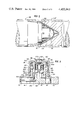
- FIG. 3 is a side sectional view of the fuze according to the invention in an unarmed and initial position
- FIG. 4 is a view similar to FIG. 3 of the fuze in a semi-armed position.
- FIG. 5 is a view similar to FIG. 3 of the fuze in its fully armed position.
- a random time delay fuze which comprises a fuze base 10, a cup guide portion 12, a piston 20 and a cup 22 whose inner wall 22b forms a cylinder for piston 20.
- Cup 22 is movably mounted over a column 12a of the cup guide portion 12.
- the fuze base includes a slide track 18 which slidably receives a detonator slider 14 which carries a detonator 15.
- Detonator slider 14 carries a bore rider 16 which is in the form of a pin which rides within a bore 17 which extends through the base 10 and into the slide track 18.
- the fuze includes a firing pin 24, a firing pin spring 26, a piston spring 28 and locking balls 30 and 32.
- Cup 22 is provided with three guide pins 34 which ride in three L-shaped grooves 36 formed in the cup guide portion column 12a.
- Piston 20 includes O-ring flanges 38 and 38A which carries a floating O-ring 40.
- the fuze is shown in its initial or unarmed position.
- slider 14 In this position slider 14 is in its right hand position with detonator 15 misaligned with essential axis 42 of the firing pin 24 and of the fuze as a whole.
- Slider 14 with bore rider 16 has a center of gravity which is to the left of axis 42, so that with a spinning movement of the fuze as a whole, the slider 14 will tend to move to the left, through centrifugal force, to cause detonator 15 to move into its aligned position shown, for example, in FIG. 5.
- the fuze 50 is mated with an explosive charge in a Grenade 44, and nested with a plurality of other Grenades, such as Grenade 44' in a tube of a projectile, not shown.
- the fuze, generally designated 50 includes a stabilization ribbon 48 which is connected to the top of cup 22 at a ribbon connection 22a.
- the stabilization ribbon 48 is folded for deployment around the top of fuze 50 and held in position, with the fuze 50 and the grenade 44 as a whole, by the shaped charge liner 52 of Grenade 44', for example.
- the shaped charge liner 52, or the projectile tube act with the bore rider 16 to prevent movement of the slider 14, when the fuze with its subarmament is nested within the projectile tube, as an added safety feature.
- a fuze base 10 includes a column portion 10a which defines a firing pin cylinder 10b. Firing pin 24 is positioned in firing pin cylinder 10b and held against the bias of firing pin spring 26 by locking balls 30 which bear against a conical portion of firing pin 24 and are contained within radial bores 10c of column 10a. Column 10a is in turn positioned within a cylindrical space defined by piston 20. Column 10a also includes a flange 10d which bears against piston spring 28.
- Piston 20 includes a slider lock pin 54 which extends into a bore 14a of the slider 14. With the piston in its lowermost position as shown in FIG. 3, slider 14 is thus prevented from moving, in addition, by the lock pin 54.
- Lock pin 54 extends through a suitably provided bore in the base 10, for this purpose.
- Piston 20 is held in its lowered position by three locking balls 32 each of which is held in radial bores 12b of column 12a between an annular groove 20a on the outside of piston 20, and the inner wall 22b of cup 22. Piston 20 is also provided with a bore 56 which receives a mounting ring 58 which in turn carries an air or fluid restrictor 60, whose function and construction will be explained hereinunder.
- FIG. 4 which shown an intermediate or semiarmed configuration of the fuze
- the ribbon 48 is presented to the surrounding air stream.
- Ribbon 48 stabilizes the position of the grenade, and at the same time, the air resistance produced by ribbon 48 causes both a relative rotation between the cup 22 and base 10, and also a displacement of cup 22 upwardly.
- the relative rotation is established due to the spin imparted on the grenade by the spinning projectile and a resistance to such spin caused by the air resistance of stabilization ribbon 48.
- the relative rotation thus permits the movement of guide pins 34 from the lower leg portions of L-shaped grooves 36, into the longitudinal portions thereof.
- Flange 38 of piston 20 is provided with O-ring 40 which bears against the inner wall 22b of cup 22. While O-ring 40 usually provides an air seal for a cylinder space 62 defined between cup 22 and piston 20, the lifting of cup 22 through the action of ribbon 48 forces the O-ring 40 to the scallopped flange 38a of piston 20 to defeat the air sealing function thus permitting space 62 to fill with air, so that the fuze takes on the configuration shown in FIG. 4. At the instant cup 22 is fully extended by the ribbon 48, piston 20 will rapidly move approximately 0.010 inch to bear against O-ring 40 thus providing a seal for space 62. At this moment, air in space 62 is compressed by the force of spring 28 and metered through the porous medium 60.
- the floating o-ring 40 fits loosely within the flanges 38 and 38A of the piston 20, but has an interference fit of a few thousandths of an inch with the bore of the cup cavity.
- the floating o-ring is used as a check valve for the fuze design.
- the o-ring 40 is moved up to the upper scallopped flange 38A allowing air to enter around the inside diameter of the o-ring 40 and pass through the vented flange 38A into space 62.
- the piston 20 begins to move into the firing mode under the force of piston spring 28. As the piston moves, the o-ring comes in contact with the lower flange 38 of the piston, which then acquires a seal.
- centrifugal force also acts on slider 42 to cause it to move to the left as shown by arrow 68. Such movement is also permitted due to the disengagement of lock pin 54 from bore 14a of slider 14.
- FIG. 5 shows a fully armed configuration of the fuze.
- the cross-sectional view is taken at a slightly rotated position as compared to FIGS. 3 and 4 so as to illustrate the movement of firing pin locking balls 30.
- piston 20 After the aforementioned time delay, piston 20 will be in its fully up position shown in FIG. 5. In this position, the bottom edge 20b of piston 20 will pass locking balls 30. To the combined action of centrifugal force and also the inclined surfaces of firing pin 24 which bears against balls 30, balls 30 will be forced outwardly to release firing pin 24. At this point firing pin 24 moves downwardly under the influence of its firing pin spring 26.
- Spring 26 can be selected either to have sufficient force to cause firing pin 24 to stroke detonator 15 and detonate it, or merely to move firing pin 24 beyond locking balls 30, whereby firing pin 24 strikes deonator 15 with sufficient force only after impact.
- restrictor 60 is made of porous polypropylene plastic. Ten layers of 0.001 in. thick plastic film is utilized as the restrictor and mounted in restrictor ring 58 for positioning on piston 20.
- the plastic material used in one form of the invention is known as Celgard 2402® which is a trademark of the Celanese Corp. for isotactic homopolymer polypropylene film.
- the properties and microporosity of the film is given in the following table.
- the time delay of fuze arming can be varied by varying the number of laminations of the plastic film, by changing the plastic film to plastic film of different porosities, and also by varying the force of piston spring 28.
Landscapes
- Engineering & Computer Science (AREA)
- General Engineering & Computer Science (AREA)
- Toys (AREA)
Abstract
Description
______________________________________
Properties of Microporous Polypropylene Film
                                  ASTM
Property      Measurement
                         Unit     Test Method
______________________________________
Porosity      38         &        D-2873
Nominal thickness
              1          mil
Area Factor   50,000     sq.in./lb
Effective pore size
              0.02       μm
Critical surface tension
              35         dynes/cm D-2573
Ultimate tensile strength
MD            20,000     psi      D-882
TD            2,000      psi      D-881
Ultimate elongation
MD            50         %        D-882
TD            >250       %        D-882
Heat-seal range
              300 to 350 °F.
Shrinkage     <5         %        D-1204,
MD understrained                  60 min, 90° C.
______________________________________
Claims (14)
Priority Applications (1)
| Application Number | Priority Date | Filing Date | Title |
|---|---|---|---|
| US06/392,495 US4455940A (en) | 1982-06-28 | 1982-06-28 | Random time delay fuze |
Applications Claiming Priority (1)
| Application Number | Priority Date | Filing Date | Title |
|---|---|---|---|
| US06/392,495 US4455940A (en) | 1982-06-28 | 1982-06-28 | Random time delay fuze |
Publications (1)
| Publication Number | Publication Date |
|---|---|
| US4455940A true US4455940A (en) | 1984-06-26 |
Family
ID=23550821
Family Applications (1)
| Application Number | Title | Priority Date | Filing Date |
|---|---|---|---|
| US06/392,495 Expired - Fee Related US4455940A (en) | 1982-06-28 | 1982-06-28 | Random time delay fuze |
Country Status (1)
| Country | Link |
|---|---|
| US (1) | US4455940A (en) |
Cited By (23)
| Publication number | Priority date | Publication date | Assignee | Title |
|---|---|---|---|---|
| US4658725A (en) * | 1984-12-19 | 1987-04-21 | Diehl Gmbh & Co. | Fuse for a small bomb |
| US4762066A (en) * | 1986-07-22 | 1988-08-09 | Diehl Gmbh & Co. | Fuze for a parachute-stabilized or band-stabilized small bomb which rotates during flight |
| US4777879A (en) * | 1986-04-08 | 1988-10-18 | Instalaza, S.A. | Fuze for an explosive shell |
| US4811664A (en) * | 1987-03-31 | 1989-03-14 | The State Of Israel, Ministry Of Defence, Israel Military Industries | Fuse for sub-munition warhead |
| US4848235A (en) * | 1986-09-12 | 1989-07-18 | Diehl Gmbh & Co. | Submunition member with laterally outwardly-movable target detection device |
| US5022325A (en) * | 1989-07-29 | 1991-06-11 | Rheinmetall Gmbh | Fuze for bomblet projectile |
| US5046424A (en) * | 1989-07-29 | 1991-09-10 | Rheinmetall Gmbh | Fuze for a bomblet projectile |
| US5048419A (en) * | 1989-07-29 | 1991-09-17 | Rheinmetall Gmbh | Bomblet fuze |
| US5067410A (en) * | 1990-12-21 | 1991-11-26 | The United States Of America As Represented By The Secretary Of The Army | Flexible wing |
| US6142079A (en) * | 1998-12-03 | 2000-11-07 | The United States Of America As Represented By The Secretary Of The Army | Area denial munition system |
| US6237495B1 (en) * | 1999-02-04 | 2001-05-29 | Chartered Ammunition Industries Pte Ltd | Self-destructing impact fuse |
| US6318269B1 (en) * | 1999-04-15 | 2001-11-20 | Rheinmetall W & M Gmbh | Air current operated projectile fuze |
| US6405652B1 (en) * | 1999-04-15 | 2002-06-18 | Rheinmetall W & M Gmbh | Projectile fuze operated by a stabilization band of the projectile |
| US6530324B1 (en) * | 2001-06-13 | 2003-03-11 | Kdi Precision Products, Inc. | Fuze mechanism for a munition |
| US20040020398A1 (en) * | 2000-07-03 | 2004-02-05 | Torsten Ronn | Subcalibre kinetic energy projectile |
| US6874425B1 (en) | 2001-05-18 | 2005-04-05 | Day & Zimmermann, Inc. | Projectile carrying sub-munitions |
| US20060124018A1 (en) * | 2002-11-08 | 2006-06-15 | Graham John A | Explosive-activated safe-arm device |
| US20080072781A1 (en) * | 2006-09-25 | 2008-03-27 | Chang Industry, Inc. | System and method for safing and arming a bore-launched projectile |
| KR101234548B1 (en) * | 2010-09-13 | 2013-02-19 | 국방과학연구소 | Device for activating thermal battery for artillery ammunition |
| CN104061827A (en) * | 2014-06-26 | 2014-09-24 | 江南工业集团有限公司 | Water pressure type underwater ignition device |
| US8925538B2 (en) * | 2012-11-15 | 2015-01-06 | Carlton Chong | Reusable distraction device simulator |
| CN104533877A (en) * | 2014-12-19 | 2015-04-22 | 常州液压成套设备厂有限公司 | Servomotor with automatic hydraulic locking function |
| WO2021226638A1 (en) | 2020-05-06 | 2021-11-11 | Bjorkemar Construction And Consulting (South Africa) (Pty) Ltd | Transplanter and method of planting seedlings |
Citations (6)
| Publication number | Priority date | Publication date | Assignee | Title |
|---|---|---|---|---|
| US3724385A (en) * | 1971-09-20 | 1973-04-03 | Us Navy | Fuze having a pneumatic and inertia arming system |
| US3913483A (en) * | 1972-08-11 | 1975-10-21 | Us Army | Grenade with fuze |
| US3938438A (en) * | 1971-04-12 | 1976-02-17 | The United States Of America As Represented By The Secretary Of The Navy | Pressure-armed explosive apparatus |
| US3962974A (en) * | 1973-01-04 | 1976-06-15 | The United States Of America As Represented By The Secretary Of The Navy | Pressure-armed ordnance fuze |
| US3998164A (en) * | 1975-12-15 | 1976-12-21 | The United States Of America As Represented By The Secretary Of The Army | Self-destruct delay fuze |
| US4389940A (en) * | 1976-04-02 | 1983-06-28 | Raytheon Company | Antipersonnel mine |
-
1982
- 1982-06-28 US US06/392,495 patent/US4455940A/en not_active Expired - Fee Related
Patent Citations (6)
| Publication number | Priority date | Publication date | Assignee | Title |
|---|---|---|---|---|
| US3938438A (en) * | 1971-04-12 | 1976-02-17 | The United States Of America As Represented By The Secretary Of The Navy | Pressure-armed explosive apparatus |
| US3724385A (en) * | 1971-09-20 | 1973-04-03 | Us Navy | Fuze having a pneumatic and inertia arming system |
| US3913483A (en) * | 1972-08-11 | 1975-10-21 | Us Army | Grenade with fuze |
| US3962974A (en) * | 1973-01-04 | 1976-06-15 | The United States Of America As Represented By The Secretary Of The Navy | Pressure-armed ordnance fuze |
| US3998164A (en) * | 1975-12-15 | 1976-12-21 | The United States Of America As Represented By The Secretary Of The Army | Self-destruct delay fuze |
| US4389940A (en) * | 1976-04-02 | 1983-06-28 | Raytheon Company | Antipersonnel mine |
Cited By (25)
| Publication number | Priority date | Publication date | Assignee | Title |
|---|---|---|---|---|
| US4658725A (en) * | 1984-12-19 | 1987-04-21 | Diehl Gmbh & Co. | Fuse for a small bomb |
| US4777879A (en) * | 1986-04-08 | 1988-10-18 | Instalaza, S.A. | Fuze for an explosive shell |
| US4762066A (en) * | 1986-07-22 | 1988-08-09 | Diehl Gmbh & Co. | Fuze for a parachute-stabilized or band-stabilized small bomb which rotates during flight |
| US4848235A (en) * | 1986-09-12 | 1989-07-18 | Diehl Gmbh & Co. | Submunition member with laterally outwardly-movable target detection device |
| US4811664A (en) * | 1987-03-31 | 1989-03-14 | The State Of Israel, Ministry Of Defence, Israel Military Industries | Fuse for sub-munition warhead |
| US5022325A (en) * | 1989-07-29 | 1991-06-11 | Rheinmetall Gmbh | Fuze for bomblet projectile |
| US5046424A (en) * | 1989-07-29 | 1991-09-10 | Rheinmetall Gmbh | Fuze for a bomblet projectile |
| US5048419A (en) * | 1989-07-29 | 1991-09-17 | Rheinmetall Gmbh | Bomblet fuze |
| US5067410A (en) * | 1990-12-21 | 1991-11-26 | The United States Of America As Represented By The Secretary Of The Army | Flexible wing |
| US6142079A (en) * | 1998-12-03 | 2000-11-07 | The United States Of America As Represented By The Secretary Of The Army | Area denial munition system |
| US6237495B1 (en) * | 1999-02-04 | 2001-05-29 | Chartered Ammunition Industries Pte Ltd | Self-destructing impact fuse |
| US6405652B1 (en) * | 1999-04-15 | 2002-06-18 | Rheinmetall W & M Gmbh | Projectile fuze operated by a stabilization band of the projectile |
| US6318269B1 (en) * | 1999-04-15 | 2001-11-20 | Rheinmetall W & M Gmbh | Air current operated projectile fuze |
| US20040020398A1 (en) * | 2000-07-03 | 2004-02-05 | Torsten Ronn | Subcalibre kinetic energy projectile |
| US6895864B2 (en) * | 2000-07-03 | 2005-05-24 | Borfors Defence Ab | Subcalibre kinetic energy projectile |
| US6874425B1 (en) | 2001-05-18 | 2005-04-05 | Day & Zimmermann, Inc. | Projectile carrying sub-munitions |
| US6530324B1 (en) * | 2001-06-13 | 2003-03-11 | Kdi Precision Products, Inc. | Fuze mechanism for a munition |
| US20060124018A1 (en) * | 2002-11-08 | 2006-06-15 | Graham John A | Explosive-activated safe-arm device |
| US20080072781A1 (en) * | 2006-09-25 | 2008-03-27 | Chang Industry, Inc. | System and method for safing and arming a bore-launched projectile |
| KR101234548B1 (en) * | 2010-09-13 | 2013-02-19 | 국방과학연구소 | Device for activating thermal battery for artillery ammunition |
| US8925538B2 (en) * | 2012-11-15 | 2015-01-06 | Carlton Chong | Reusable distraction device simulator |
| CN104061827A (en) * | 2014-06-26 | 2014-09-24 | 江南工业集团有限公司 | Water pressure type underwater ignition device |
| CN104533877A (en) * | 2014-12-19 | 2015-04-22 | 常州液压成套设备厂有限公司 | Servomotor with automatic hydraulic locking function |
| CN104533877B (en) * | 2014-12-19 | 2016-08-31 | 常州液压成套设备厂有限公司 | There is the servomotor of automatic hydraulic lock function |
| WO2021226638A1 (en) | 2020-05-06 | 2021-11-11 | Bjorkemar Construction And Consulting (South Africa) (Pty) Ltd | Transplanter and method of planting seedlings |
Similar Documents
| Publication | Publication Date | Title |
|---|---|---|
| US4455940A (en) | Random time delay fuze | |
| US3913483A (en) | Grenade with fuze | |
| US2664822A (en) | Fuze | |
| DE3333312C2 (en) | ||
| US4311097A (en) | Dual underwater safety fuse | |
| US3557701A (en) | Hand-grenade fuze | |
| US5549047A (en) | Submunition fuse with a nondelay self-destruct firing device | |
| US3118379A (en) | Fuze for a gyratory projectile | |
| US20190145747A1 (en) | Time-Delayed Multi-Charged Diversionary Device | |
| US3906860A (en) | Dual purpose projectile | |
| US4241660A (en) | Projectile | |
| ZA200106430B (en) | Self destructing impact fuse. | |
| US3919941A (en) | Liquid timing device | |
| EP2102581B1 (en) | Self destruction impact fuse | |
| US3640225A (en) | Fuze apparatus | |
| US3439610A (en) | Folding munition | |
| US3636880A (en) | Control apparatus | |
| US2845866A (en) | Fuse for a projectile and applications thereof | |
| US4160414A (en) | Projectile having a delay-action firing mechanism | |
| US4056058A (en) | Safety fuse for underwater artefacts | |
| US3603258A (en) | Mechanical fuzing system | |
| US2405653A (en) | Fuse for automatic destruction of shells | |
| US4018164A (en) | Projectile fuze containing a floating body | |
| US2493278A (en) | Combined fuse | |
| US4015533A (en) | Dual pressure sensing safing and arming mechanism |
Legal Events
| Date | Code | Title | Description |
|---|---|---|---|
| AS | Assignment |
Owner name: UNITED STATES OF AMERICA AS REPRESENTED BY THE SEC Free format text: ASSIGNMENT OF ASSIGNORS INTEREST. SUBJECT TO LICENSE RECITED.;ASSIGNOR:AEROJET ORDNANCE CO.;REEL/FRAME:004306/0441 Effective date: 19820528 Owner name: AEROJET ORDNANCE COMPANY Free format text: ASSIGNMENT OF ASSIGNORS INTEREST.;ASSIGNOR:FURUIKE, HARUO H.;REEL/FRAME:004306/0436 Effective date: 19820519 |
|
| FEPP | Fee payment procedure |
Free format text: PAYOR NUMBER ASSIGNED (ORIGINAL EVENT CODE: ASPN); ENTITY STATUS OF PATENT OWNER: LARGE ENTITY |
|
| REMI | Maintenance fee reminder mailed | ||
| FPAY | Fee payment |
Year of fee payment: 4 |
|
| SULP | Surcharge for late payment | ||
| FPAY | Fee payment |
Year of fee payment: 8 |
|
| SULP | Surcharge for late payment | ||
| REMI | Maintenance fee reminder mailed | ||
| REMI | Maintenance fee reminder mailed | ||
| LAPS | Lapse for failure to pay maintenance fees | ||
| FP | Lapsed due to failure to pay maintenance fee |
Effective date: 19960626 |
|
| STCH | Information on status: patent discontinuation |
Free format text: PATENT EXPIRED DUE TO NONPAYMENT OF MAINTENANCE FEES UNDER 37 CFR 1.362 |