US4446818A - Hanger for conveyor tubes and the like - Google Patents
Hanger for conveyor tubes and the like Download PDFInfo
- Publication number
- US4446818A US4446818A US06/383,464 US38346482A US4446818A US 4446818 A US4446818 A US 4446818A US 38346482 A US38346482 A US 38346482A US 4446818 A US4446818 A US 4446818A
- Authority
- US
- United States
- Prior art keywords
- hanger
- tube
- series
- conveyor
- defining
- Prior art date
- Legal status (The legal status is an assumption and is not a legal conclusion. Google has not performed a legal analysis and makes no representation as to the accuracy of the status listed.)
- Expired - Lifetime
Links
- 239000012212 insulator Substances 0.000 claims description 3
- 244000144977 poultry Species 0.000 description 8
- 235000013594 poultry meat Nutrition 0.000 description 8
- 238000005452 bending Methods 0.000 description 2
- 238000006073 displacement reaction Methods 0.000 description 2
- 238000005096 rolling process Methods 0.000 description 2
- 239000000725 suspension Substances 0.000 description 2
- 241000287828 Gallus gallus Species 0.000 description 1
- 238000009434 installation Methods 0.000 description 1
- 239000000463 material Substances 0.000 description 1
- 230000013011 mating Effects 0.000 description 1
- 230000004048 modification Effects 0.000 description 1
- 238000012986 modification Methods 0.000 description 1
Images


Classifications
-
- A—HUMAN NECESSITIES
- A01—AGRICULTURE; FORESTRY; ANIMAL HUSBANDRY; HUNTING; TRAPPING; FISHING
- A01K—ANIMAL HUSBANDRY; AVICULTURE; APICULTURE; PISCICULTURE; FISHING; REARING OR BREEDING ANIMALS, NOT OTHERWISE PROVIDED FOR; NEW BREEDS OF ANIMALS
- A01K5/00—Feeding devices for stock or game ; Feeding wagons; Feeding stacks
- A01K5/02—Automatic devices
- A01K5/0258—Automatic devices with endless screws
-
- A—HUMAN NECESSITIES
- A01—AGRICULTURE; FORESTRY; ANIMAL HUSBANDRY; HUNTING; TRAPPING; FISHING
- A01K—ANIMAL HUSBANDRY; AVICULTURE; APICULTURE; PISCICULTURE; FISHING; REARING OR BREEDING ANIMALS, NOT OTHERWISE PROVIDED FOR; NEW BREEDS OF ANIMALS
- A01K39/00—Feeding or drinking appliances for poultry or other birds
- A01K39/01—Feeding devices, e.g. chainfeeders
- A01K39/012—Feeding devices, e.g. chainfeeders filling automatically, e.g. by gravity from a reserve
- A01K39/0125—Panfeeding systems; Feeding pans therefor
Definitions
- This invention relates generally to conveyor systems for poultry feed and like materials, and more particularly concerns a support hanger or support structure for carrying a conveyor tube in a pre-determined location.
- Tube conveyors are widely used to transport feed in poultry feeding systems.
- a helical spring-like auger element is rotated within a conveyor tube to convey granular feed along the tube.
- One such auger conveyor tube is disclosed in Swartzendruber U.S. Pat. No. 4,317,430.
- the auger conveyor tube includes a series of elongated cylindrical tube sections, which can be joined together by bell-and-spigot joints and supported by hangers.
- Each tube section is formed by curving or rolling a tube sheet so as to form a radially extending flange-like tube closure seam.
- Each tube section is also perforated to provide one or more feed drop-out holes or apertures, and these apertures are advantageously located at a given angular displacement or distance from the tube seam.
- a feed receiving and delivery device such as a feeder pan.
- a feeder pan One such pan is shown, for example, in U.S. Pat. No. 3,911,868.
- the assembled conveyor tube must be supported or hung in the poultry house at a number of locations along the tube length.
- the tube is so supported as to keep it relatively straight and immobile.
- the assembled tube sections must be precisely supported in various angular orientations or amounts of angular displacement, so as to encourage good feed delivery as explained above.
- a more specific object is to provide such a conveyor tube hanger device which will permit a conveyor tube section to be located in any one of a great number of angularly discrete positions, in order that the desired helical array of tube section drop-out apertures can be provided.
- Another object is to provide such a tube hanger element which can be easily and inexpensively manufactured and installed.
- FIG. 1 is a perspective view showing a poultry feed conveyor system utilizing an auger tube which is suspended or supported by the novel tube hanger;
- FIG. 2 is a fragmentary elevational view in partial section showing a portion of the auger conveyor and the novel conveyor hanger;
- FIG. 3 is a fragmentary exploded view showing the conveyor tube and associated novel hanger
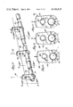
- FIG. 4 is a front elevational view showing the conveyor tube and associated novel hanger as they may appear during conveyor and hanger installation;
- FIG. 5 is a front elevational view similar to FIG. 4 and showing the novel hanger in various angularly displaced positions;
- FIG. 6 is a front elevational view similar to FIGS. 4 and 5 and showing, in diagramatic form, a multiple series of hanger and tube location positions;
- FIG. 7 is a perspective view showing several of the novel hangers and the assembled conveyor system with the tube sections located in a desired or preferred array;
- FIG. 8 is a cross-sectional view taken substantially in the plane of line 8--8 in FIG. 7;
- FIG. 9 is a cross-sectional view taken substantially in the plane of line 9--9 in FIG. 7;
- FIG. 10 is a cross-sectional view taken substantially in the plane of line 10--10 in FIG. 7.
- FIG. 1 there is shown a conveyor system 10 for conveying feed from a hopper or bin structure 11 to feeder pans 12 for consumption by broiler chickens or other poultry C.
- a centerless helical auger member 13 is disposed within an auger conveyor tube 14, as shown in FIG. 2.
- feed is moved from the bin 11 along the tube 14 to drop-out apertures 15, 16 and 17 (FIGS. 3 and 8-10) for delivery to the underlying feeders or feed pans 12.
- Conveyor suspension cables 18 are here secured to a poultry house roof or other support means (not shown).
- the conveyor tube 14 includes in series of tube sections 19, 20 and 21 interconnected by bell-and-spigot joint structure 22.
- these tube sections 19, 20 and 21 are formed by rolling or bending tube sheets into a cylindrical shape. The ends of these tube sheets are formed into a radially extending, tube-closing flange structure 23.
- One form of such tube flange structure is disclosed and claimed in Swartzendruber U.S. Pat. No. 4,317,430.
- the feed drop-out apertures in each section 19-21 are defined in the formed tube, and each aperture is located at a predetermined angular position relative to the tube section flange 23.
- this conveyor tube 14 should be supported or suspended in a relatively linear or straight condition for proper operation, and the drop-out holes 15, 16, 17 should be helically arrayed.
- the illustrated suspension system includes the novel hanger members 25.
- the hanger 25 defines a lower hole 30 for receiving the conveyor tube or tube section 19, 20 or 21.
- a plurality of recesses 31, 32, 33 communicate with this tube hole 30.
- Each recesses 31-33 is adapted to mate with the tube flange 23, and thus locate the tube 19, 20 or 21 and feed drop-out aperture 15, 16 or 17 in one of a series of discrete angularly offset, distinct, positions.
- the hanger 25 is here made to include a body portion 35 and a cradle portion 36.
- the cradle portion 36 is pivotally connected to the body portion 35 by a rivet 37 or other pivotal connector.
- Mating holes 38, 39 are formed to receive a bolt or other fastener 40 so as to completely secure the cradle 36 to the body portion 35 when the tube is installed in and on the hanger 25.
- assembly is made easier by forming all the recesses 31-33 in the cradle portion 36 of the hanger 25.
- FIGS. 5 and 6 show that, when the tube 14 is installed in and on the hanger 25, attachment of the cable 18 to the hanger 25 in any one of the selected attachment holes 46-48 will cause the carried conveyor tube section 19-21 to be located in a corresponding angular position.
- first series of flange-receiving slots 31-33 in the bottom of the hanger 25 and the second series of attachment holes 46-48 in the top of the hanger 25 provide a multiple series of angular positions in which the conveyor tubes can be carried. For example, if five recesses are provided, and if nine attachment holes are provided, some forty-five angularly discrete positions of tube carry can be provided. Each position can be slightly angularly offset from the others, as shown in FIG. 6. By providing this great number of angular tube positions, precise angular adjustment of the tube sections and the feed drop-out apertures can be provided.
- an electrified anti-roost wire 50 is customarily installed immediately above the conveyor 14, to prevent poultry from roosting on the conveyor and possibly bending or otherwise damaging the conveyor.
- a secondary hole 52 is provided in the hanger body 35 between the tube hole 30 and the adjustment holes 45.
- annular insulator 54 is installed in this secondary hole 52 to insure that the anti-roost wire does not electrically contact the hanger member 25.
Landscapes
- Life Sciences & Earth Sciences (AREA)
- Environmental Sciences (AREA)
- Birds (AREA)
- Animal Husbandry (AREA)
- Biodiversity & Conservation Biology (AREA)
- Feeding And Watering For Cattle Raising And Animal Husbandry (AREA)
Abstract
Description
Claims (8)
Priority Applications (1)
| Application Number | Priority Date | Filing Date | Title |
|---|---|---|---|
| US06/383,464 US4446818A (en) | 1982-06-01 | 1982-06-01 | Hanger for conveyor tubes and the like |
Applications Claiming Priority (1)
| Application Number | Priority Date | Filing Date | Title |
|---|---|---|---|
| US06/383,464 US4446818A (en) | 1982-06-01 | 1982-06-01 | Hanger for conveyor tubes and the like |
Publications (1)
| Publication Number | Publication Date |
|---|---|
| US4446818A true US4446818A (en) | 1984-05-08 |
Family
ID=23513282
Family Applications (1)
| Application Number | Title | Priority Date | Filing Date |
|---|---|---|---|
| US06/383,464 Expired - Lifetime US4446818A (en) | 1982-06-01 | 1982-06-01 | Hanger for conveyor tubes and the like |
Country Status (1)
| Country | Link |
|---|---|
| US (1) | US4446818A (en) |
Cited By (7)
| Publication number | Priority date | Publication date | Assignee | Title |
|---|---|---|---|---|
| US4722301A (en) * | 1986-05-08 | 1988-02-02 | Strong George W | Brooder feeding apparatus |
| US4911387A (en) * | 1988-06-27 | 1990-03-27 | Creative Systems Engineering, Inc. | Modular conduit system |
| US5133523A (en) * | 1988-06-27 | 1992-07-28 | Creative Systems Engineering, Inc.02 | Suspendable conduit bracket lock system |
| US20050156089A1 (en) * | 2004-01-16 | 2005-07-21 | Frederick Diggle | Communication cable support |
| US20150233496A1 (en) * | 2014-02-19 | 2015-08-20 | Entertainment Structural Products | Multi-Connection Truss Pick |
| CN104942516A (en) * | 2015-07-28 | 2015-09-30 | 上海锅炉厂有限公司 | Longitudinal tube bank hoisting device |
| US20160186922A1 (en) * | 2014-12-31 | 2016-06-30 | Shenzhen Wanjia Lighting Co., Ltd. | Meshing type angle fixing structure |
Citations (15)
| Publication number | Priority date | Publication date | Assignee | Title |
|---|---|---|---|---|
| US789830A (en) * | 1904-11-25 | 1905-05-16 | Nils A Zetterlund | Cable-hanger. |
| GB935868A (en) * | 1961-09-25 | 1963-09-04 | Leonard George Elt | Improvements in or relating to livestock feeding appliances |
| US3223228A (en) * | 1963-03-06 | 1965-12-14 | Starline | Animal feeder |
| US3230933A (en) * | 1963-10-04 | 1966-01-25 | Chore Time Equipment | Poultry feeder apparatus |
| US3508302A (en) * | 1968-07-03 | 1970-04-28 | Theodore R Settanni | Clip device for adjustment of suspended ceilings,and ceiling incorporating the same |
| US3511215A (en) * | 1967-12-26 | 1970-05-12 | Chore Time Equipment | Poultry feeder |
| US3598087A (en) * | 1969-03-17 | 1971-08-10 | Chore Time Equipment | Restricted feeding apparatus |
| DE2133022A1 (en) * | 1971-07-02 | 1973-01-18 | Kabel Und Metallwerke Gutchoff | TUBULAR CONSTRUCTION THIN WALL THICKNESS |
| US3757830A (en) * | 1970-02-19 | 1973-09-11 | Manuf Systems Inc | Rectangular air duct |
| US3799116A (en) * | 1972-05-22 | 1974-03-26 | Chore Time Equipment | Method and apparatus for installing feeding system conveyor tubes |
| US3911868A (en) * | 1973-07-12 | 1975-10-14 | Chore Time Equipment | Poultry feeder |
| US4003339A (en) * | 1972-11-06 | 1977-01-18 | Chore-Time Equipment, Inc. | Method and apparatus for delivering large quantities of feed and the like |
| US4267800A (en) * | 1980-02-27 | 1981-05-19 | Keller Morris C | Suspended watering system for poultry house |
| US4317430A (en) * | 1980-09-02 | 1982-03-02 | Chore-Time Equipment, Inc. | Auger conveyor tube |
| US4351506A (en) * | 1981-03-02 | 1982-09-28 | Ohai Reynolds K | Loop for leveling a hanging lamp |
-
1982
- 1982-06-01 US US06/383,464 patent/US4446818A/en not_active Expired - Lifetime
Patent Citations (15)
| Publication number | Priority date | Publication date | Assignee | Title |
|---|---|---|---|---|
| US789830A (en) * | 1904-11-25 | 1905-05-16 | Nils A Zetterlund | Cable-hanger. |
| GB935868A (en) * | 1961-09-25 | 1963-09-04 | Leonard George Elt | Improvements in or relating to livestock feeding appliances |
| US3223228A (en) * | 1963-03-06 | 1965-12-14 | Starline | Animal feeder |
| US3230933A (en) * | 1963-10-04 | 1966-01-25 | Chore Time Equipment | Poultry feeder apparatus |
| US3511215A (en) * | 1967-12-26 | 1970-05-12 | Chore Time Equipment | Poultry feeder |
| US3508302A (en) * | 1968-07-03 | 1970-04-28 | Theodore R Settanni | Clip device for adjustment of suspended ceilings,and ceiling incorporating the same |
| US3598087A (en) * | 1969-03-17 | 1971-08-10 | Chore Time Equipment | Restricted feeding apparatus |
| US3757830A (en) * | 1970-02-19 | 1973-09-11 | Manuf Systems Inc | Rectangular air duct |
| DE2133022A1 (en) * | 1971-07-02 | 1973-01-18 | Kabel Und Metallwerke Gutchoff | TUBULAR CONSTRUCTION THIN WALL THICKNESS |
| US3799116A (en) * | 1972-05-22 | 1974-03-26 | Chore Time Equipment | Method and apparatus for installing feeding system conveyor tubes |
| US4003339A (en) * | 1972-11-06 | 1977-01-18 | Chore-Time Equipment, Inc. | Method and apparatus for delivering large quantities of feed and the like |
| US3911868A (en) * | 1973-07-12 | 1975-10-14 | Chore Time Equipment | Poultry feeder |
| US4267800A (en) * | 1980-02-27 | 1981-05-19 | Keller Morris C | Suspended watering system for poultry house |
| US4317430A (en) * | 1980-09-02 | 1982-03-02 | Chore-Time Equipment, Inc. | Auger conveyor tube |
| US4351506A (en) * | 1981-03-02 | 1982-09-28 | Ohai Reynolds K | Loop for leveling a hanging lamp |
Cited By (11)
| Publication number | Priority date | Publication date | Assignee | Title |
|---|---|---|---|---|
| US4722301A (en) * | 1986-05-08 | 1988-02-02 | Strong George W | Brooder feeding apparatus |
| US4911387A (en) * | 1988-06-27 | 1990-03-27 | Creative Systems Engineering, Inc. | Modular conduit system |
| US5133523A (en) * | 1988-06-27 | 1992-07-28 | Creative Systems Engineering, Inc.02 | Suspendable conduit bracket lock system |
| WO1990014541A1 (en) * | 1989-05-22 | 1990-11-29 | Daigle Robert V | Modular conduit system |
| US20050156089A1 (en) * | 2004-01-16 | 2005-07-21 | Frederick Diggle | Communication cable support |
| US7073761B2 (en) * | 2004-01-16 | 2006-07-11 | Bellsouth Intellectual Property Corporation | Communication cable support |
| US20150233496A1 (en) * | 2014-02-19 | 2015-08-20 | Entertainment Structural Products | Multi-Connection Truss Pick |
| US10295087B2 (en) | 2014-02-19 | 2019-05-21 | Entertainment Structural Products, Inc. | Multi-connection truss pick |
| US20160186922A1 (en) * | 2014-12-31 | 2016-06-30 | Shenzhen Wanjia Lighting Co., Ltd. | Meshing type angle fixing structure |
| CN104942516A (en) * | 2015-07-28 | 2015-09-30 | 上海锅炉厂有限公司 | Longitudinal tube bank hoisting device |
| CN104942516B (en) * | 2015-07-28 | 2016-08-24 | 上海锅炉厂有限公司 | A kind of longitudinal pipe queues device for hoisting |
Similar Documents
| Publication | Publication Date | Title |
|---|---|---|
| US4446818A (en) | Hanger for conveyor tubes and the like | |
| US5884581A (en) | Feeding device for poultry | |
| CA1335951C (en) | Poultry feeder assembly | |
| US3911868A (en) | Poultry feeder | |
| US4070990A (en) | Feeder pan assembly | |
| US6655317B1 (en) | Adjustable poultry feeder | |
| EP0913085A1 (en) | Adjustable poultry feeder assembly | |
| KR950703275A (en) | Poultry Feeding Device | |
| EP1026802A1 (en) | Connector device for electrical cable carrier tray sections | |
| US5097798A (en) | Fowl watering system | |
| US3776191A (en) | Conveyor and trough feeder for poultry and the like | |
| US6532894B2 (en) | Anti-squirrel and rodent attachment kit | |
| US5522345A (en) | Livestock feeder | |
| US4395973A (en) | Cable hold-down apparatus | |
| US3203397A (en) | Poultry feeder | |
| US3962996A (en) | Feeding trough | |
| US5860390A (en) | Liverstock feeder | |
| US2738766A (en) | Automatic flexible conveyor poultry feeder | |
| US20060011141A1 (en) | Feed hopper | |
| US4375791A (en) | Trough feeder | |
| US3223228A (en) | Animal feeder | |
| US4760326A (en) | Protective housing and mounting apparatus for capacitive-type proximity sensor | |
| US6786178B2 (en) | Feed distribution system for poultry | |
| US4391361A (en) | Hold-down apparatus for cable conveyors | |
| US4841910A (en) | Bendable coiled wire bird perch |
Legal Events
| Date | Code | Title | Description |
|---|---|---|---|
| AS | Assignment |
Owner name: CHORE-TIME EQUIPMENT, INC., STATE ROAD 15, MILFORD Free format text: ASSIGNMENT OF ASSIGNORS INTEREST.;ASSIGNOR:RIGTERINK, PRESTON D.;REEL/FRAME:004146/0700 Effective date: 19820525 Owner name: CHORE-TIME EQUIPMENT, INC., INDIANA Free format text: ASSIGNMENT OF ASSIGNORS INTEREST;ASSIGNOR:RIGTERINK, PRESTON D.;REEL/FRAME:004146/0700 Effective date: 19820525 |
|
| STCF | Information on status: patent grant |
Free format text: PATENTED CASE |
|
| FPAY | Fee payment |
Year of fee payment: 4 |
|
| FEPP | Fee payment procedure |
Free format text: PAYOR NUMBER ASSIGNED (ORIGINAL EVENT CODE: ASPN); ENTITY STATUS OF PATENT OWNER: LARGE ENTITY |
|
| FPAY | Fee payment |
Year of fee payment: 8 |
|
| AS | Assignment |
Owner name: CTB, INC., INDIANA Free format text: MERGER;ASSIGNOR:CHORE-TIME EQUIPMENT, INC.;REEL/FRAME:006408/0209 Effective date: 19851007 |
|
| FPAY | Fee payment |
Year of fee payment: 12 |
|
| AS | Assignment |
Owner name: SOCIETY NATIONAL BANK, OHIO Free format text: COLLATERAL ASSIGNMENT & SECURITY AGREEMENT;ASSIGNOR:CTB, INC.;REEL/FRAME:007795/0681 Effective date: 19960104 |
|
| AS | Assignment |
Owner name: CTB, INC., INDIANA Free format text: RELEASE AND ASSIGNMENT OF PATENTS;ASSIGNOR:KEYBANK NATIONAL ASSOCIATION (FORMERLY KNOWN AS, SOCIETY NATIONAL BANK), AS AGENT;REEL/FRAME:008907/0257 Effective date: 19970902 |
|
| AS | Assignment |
Owner name: CTB IP, INC., DELAWARE Free format text: ASSIGNMENT OF ASSIGNORS INTEREST;ASSIGNOR:CTB, INC.;REEL/FRAME:012463/0254 Effective date: 20011001 |