US4397133A - Fill and seal machines - Google Patents
Fill and seal machines Download PDFInfo
- Publication number
- US4397133A US4397133A US06/188,839 US18883980A US4397133A US 4397133 A US4397133 A US 4397133A US 18883980 A US18883980 A US 18883980A US 4397133 A US4397133 A US 4397133A
- Authority
- US
- United States
- Prior art keywords
- closure
- containers
- machine
- closures
- container
- Prior art date
- Legal status (The legal status is an assumption and is not a legal conclusion. Google has not performed a legal analysis and makes no representation as to the accuracy of the status listed.)
- Expired - Lifetime
Links
Images


Classifications
-
- B—PERFORMING OPERATIONS; TRANSPORTING
- B65—CONVEYING; PACKING; STORING; HANDLING THIN OR FILAMENTARY MATERIAL
- B65B—MACHINES, APPARATUS OR DEVICES FOR, OR METHODS OF, PACKAGING ARTICLES OR MATERIALS; UNPACKING
- B65B7/00—Closing containers or receptacles after filling
- B65B7/16—Closing semi-rigid or rigid containers or receptacles not deformed by, or not taking-up shape of, contents, e.g. boxes or cartons
- B65B7/28—Closing semi-rigid or rigid containers or receptacles not deformed by, or not taking-up shape of, contents, e.g. boxes or cartons by applying separate preformed closures, e.g. lids, covers
- B65B7/2807—Feeding closures
Definitions
- This invention relates generally to machines for filling and sealing containers containing a liquid or semi-liquid product, and more specifically relates to a machine that has a first work station for positioning empty containers for subsequent filling, a second work station for filling the containers, and a third work station for delivering closure members to the filled containers and for sealing said containers with said closure members, and a fourth work station for ejecting the filled and sealed containers from the machine.
- Previously fill and seal machines generally incorporate perforated or apertured turntables, or carrier discs, for transporting the container or cup sought to be filled from work station to work station.
- Previously machines in the field of this invention also provide separate work stations for delivering a closure means to an individual cup means on a successive basis and for accomplishing a sealing engagement between said cup and said closure member.
- the machines of the prior art also incorporate complex drive mechanisms due to the number of work stations and due to the complex active tasks that must be performed at each station.
- the drive assemblies of the prior art generally include sprocket chains, power take off shafts, and numerous other parts such as cams, cam followers, levers, reciprocating rods and the like.
- a need is therefore seen to exist in the packaging industry generally and in the fill and seal machine industry particularly for a machine that has a reduced number of work stations and, accordingly, a reduced number of active components.
- the complex cup-ejection systems of the earlier devices is essentially eliminated by the inventive machine, in that the cups are carried from station to station along a predetermined flow path as established by a rotatable turntable that has a plurality of circumferentially spaced pockets formed about the periphery thereof.
- the pockets are in open communication with the peripheral boundary, so that removal of the cups from the pockets is accomplished when the cups impinge upon a sweep arm member disposed in path-interruptive relation thereto with the attendant rotation of the turntable, the sweep arm guiding the cups to a pick-up area.
- the pockets are closed throughout a major portion of each machine cycle by a ring-like element that at least partially surrounds the turntable, in co-planar relation thereto.
- the ring element imparts stability to the cups during the fill and seal procedure.
- the ring element is discontinuous adjacent the cup-discharge region of the machine, so that the sweep arm member can discharge the filled and sealed cups.
- the lid delivery/lid sealing work station includes a lid or closure magazine having a frame structure for transiently retaining a supply of lids in stacked relation.
- the frame structure is disposed generally in aligned relation to the various cup-carrying pockets formed in the periphery of the turntable.
- the longitudinal axis of the generally upstanding frame structure is angularly offset from the vertical by about 7°.
- a specifically disposed finger element interrupts the fall of the lid and supportingly engages the peripheral boundary of the lid.
- the finger element is orthogonally disposed relative to the longitudinal axis of the frame structure so that a lid resting partially thereon is tilted an 83° angle relative to the horizontal.
- the lip, or rim, portion of the cup requiring closure rotates into registration with the lowermost portion of the tilted lid, and a partial snap-fit engagement therebetween is effected.
- a partial snap-fit engagement therebetween is effected.
- the turntable and the operable components of the respective work stations are driven by a drive assembly that includes a power source in the form of an electric motor, a gear reduction means disposed in driven relation to the motor means, and a novel gear train that is characterized at least in part by having the individual gears that collectively form the gear train disposed in substantially unidirectional alignment with one another. Only three gears are needed to operate the geneva mechanism that rotates the turntable as required and the operable components of the work stations.
- a closely related object is to provide such a machine having a simplified drive assembly.
- a very important object is to provide such a machine wherein the lid delivery and lid seal function is performed at a single work station.
- Still another object is to provide a lid sealing means that harnesses the kinetic energy of a rotating turntable to apply a yieldable lid means to a cup in snap-fit engagement therewith.
- Yet another object is to harness such turntable motion to effectuate ejection of filled and sealed cups from the machine.
- FIG. 1 is a top plan view of the preferred embodiment of the invention.
- FIG. 2 is a side elevational view of the cup delivery, or cup drop work station.
- FIG. 3 is a side elevational view of the liquid reservoir which forms a part of the cup filling work station.
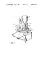
- FIG. 4 is a side elevational view of the lid delivery and lid sealing work station.
- FIG. 5 is a diagrammatic plan view of the inventive gear train that forms a part of the drive assembly for the preferred embodiment.
- FIG. 6 is a perspective view of the preferred embodiment of the invention.
- top plan view in FIG. 1 A major portion of the inventive assembly is shown in top plan view in FIG. 1 and is designated 10 as a whole.
- a top plate 12 of the machine housing is preferably rectangular, flat, and disposed substantially in a horizontal plane.
- a discharge chute 14 is parallel to but vertically offset from the plate 12, as best shown in FIG. 6.
- a drive assembly, hereinafter described, for the inventive machine 10 is disposed below the plane of the top plate 12 and is housed within the remainder of a box-like machine housing, not shown.
- a carrier means or turntable 16 is spaced upwardly of the plane of the top plate 12, in substantially parallel relation thereto.
- the turntable 16 has a circular peripheral boundary and a plurality of equi-distant, circumferentially spaced, radially disposed cut-out apertures, or pockets 18.
- the pockets 18 are in open communication with the peripheral boundary of the turntable, and are specifically configured and dimensioned to correspond in size and shape to the cups that are filled and sealed by the inventive machine, so that said cups are supportingly engaged about their respective rims at least in part by the interior edges 19 of the pockets 18.
- a stationary, dis-continuous ring element 20 partially surrounds the turntable 16, as shown in FIG. 1, and is co-planar therewith.
- the turntable 16 is removably mounted to the machine housing, and is rotatable about an axis 22.
- a geneva mechanism not shown, effects timed rotation of the turntable 16 in 45° increments, there being eight (8) cup-carrying pockets 18 formed in the turntable 16 in the preferred embodiment of the invention.
- a plurality of work stations, collectively designated 24, are disposed in circumferential relation to one another about the periphery of the turntable 16, so that the operable components of each of the work stations are in communicating relation to different ones of the pockets 18, as depicted in FIG. 1. More specifically, at the completion of each incremental advance of the turntable 16, different ones of the pockets 18 are in vertically-spaced axial alignment with the operable components of different ones of the work stations 24.
- the first work station, designated 26 conventionally supplies a container or cup to an aligned pocket 18 attendant each incremental advance of turntable 16.
- the cup delivery work station 26 includes an upstanding support member 28 that is fixedly secured to the top plate 12 of the machine housing.
- An arm 30 is disposed in overhanging relation to the turntable 16 by a cantilever-type attachment to the support member 28.
- a plurality, preferably four (4), of upstanding arms 32 are provided to retain a supply of cups or containers in stacked, internesting relation in the area bordered by said arms 32.
- the mechanism 34 for successively depositing the cups into the respective pockets 18 is known to those skilled in the pertinent art.
- the turntable 16 is driven so that it undergoes dextrorotation. Accordingly, a cup deposited in a pocket 18 by the cup drop work station 26 is transported by the turntable 16 to a point in communication with the second work station, wherein a liquid or semi-liquid product is charged into the cup.
- the means for filling the cup at this work station is an essentially conventional pumping means, designated 36 as a whole.
- a liquid reservoir 38, shown in FIG. 3, is mounted in upstanding disposition with an outlet 40, as best shown in FIG. 1, being in fluid communication with a reciprocating piston-type pump means, generally indicated as 42, and a head, or discharge spout 44.
- the amount of liquid pumped into each cup is a function of the length of the stroke of the pump's piston (not shown), and a micro-adjustment means, generally indicated as 46, is provided so that the length of the piston stroke can be finetuned to meet specific dosage requirements.
- the filled cup is next carried by the turntable 16 to the third work station which is designated 48 as a whole.
- the lids or closures are supplied to each cup, on a successive basis, and are releasably attached thereto.
- the third work station 48 includes an upstanding support member 50, an arm 52 attached thereto in cantilever fashion to overhang the periphery of the turntable 16.
- a plurality of upstanding lid retainer members 54 extend from cantilever arm 52 and are collectively arrayed to provide a gravity fed, closure magazine to supply closure members or lids 56 for the containers 58.
- a block 60 of adequate predetermined mass rests atop the generally vertical stack of lids 56 to enhance the gravity-influenced discharge of successive lids 56 from the magazine 54.
- the cantilever arm 52 is obliquely disposed relative to the turntable 16 so that the lid retaining assembly 54 disposed in orthogonal relation to the arm 52 are tilted from the vertical.
- Empirical studies have shown that the optimal amount of angular rotation of the lid retaining assembly 54 from the vertical is seven (7) degrees, although the amount of tilt can range from 5°-10° from the vertical.
- the turntable 16 is rotating from left to right, as indicated by the directional arrow 62.
- a cup 58 is shown just prior to the moment when a lid 56 is dropped thereon.
- the cup 58 is supportedly engaged about a container rim 59 by the interior edges 19 of the pocket 18 and by an adjacent portion of the ring element 20.
- a tilt-maintaining finger element 64 is attached to the cantilever arm 52 and lies in a plane parallel to the obliquely-disposed plane of the arm 52.
- the finger element 64 projects into the path of free fall of the individual lids 56 and supportingly engages, on a transient basis, a portion of each lid 56 sufficient to retain such lid 56 in an inclined position, even after such lid 56 has separated from the lid stack.
- a diametrically opposed portion thereof will engage the rim 59 of the cup 58.
- the inclined lid 56 travels into impinging relationship with a roller means 66 that is rotatably and non-translatably mounted on the cantilever arm 52 at edge 67.
- the roller means 66 has a length at least equal to the diameter of the cup lids 56 and is disposed in transverse relation to the direction of turntable 16 rotation.
- the lid 56 is made of substantially flexible materials, and accordingly yields to the roller means 66 attendant continued rotation of the turntable 16. Such yielding action on the part of the lid 56 causes the lid to conform to and snap-fittingly engage the cup 58 about the uppermost periphery of rim 59, thereby effectively sealing the cup 58 against spillage of the liquid (not shown) retained therein.
- a fixed-position sweep arm 68 is disposed downwardly of the turntable 16 and upwardly of the top plate and discharge chute 12 and 14, respectively, for guiding successive cups 58 out of the respective pockets 18 and onto the discharge chute 14 to be collected by the machine operator.
- the novel gear train for the inventive machine is shown, diagrammatically, in FIG. 5.
- Four (4) of the seven (7) gears are idlers, and are collectively designated 70.
- the outermost gears, 72 and 74 are connected in driving relation to the pump 42 and the first work station 26, respectively.
- the centrally-disposed gear 76 is the main drive gear and is is connected in driven relation to a power supply means in the form of an electric motor (not shown).
- the eight (8) position geneva mechanism (not shown) and the turntable 16 are connected in driven relation to the main gear 76.
- the only active components of the entire assembly are thus seen to be the first work station 26, second work station 42, and the turntable 16.
- the lid delivery and lid sealing means 48, as well as the filled and sealed cup ejection means 68 are essentially passive components.
- the complex drive assemblies of earlier fill and seal machines have accordingly been eliminated and the probabilities of machine malfunction have been sharply and inventively curtailed.
Landscapes
- Engineering & Computer Science (AREA)
- Mechanical Engineering (AREA)
- Closing Of Containers (AREA)
Abstract
Description
Claims (6)
Priority Applications (1)
| Application Number | Priority Date | Filing Date | Title |
|---|---|---|---|
| US06/188,839 US4397133A (en) | 1980-09-19 | 1980-09-19 | Fill and seal machines |
Applications Claiming Priority (1)
| Application Number | Priority Date | Filing Date | Title |
|---|---|---|---|
| US06/188,839 US4397133A (en) | 1980-09-19 | 1980-09-19 | Fill and seal machines |
Publications (1)
| Publication Number | Publication Date |
|---|---|
| US4397133A true US4397133A (en) | 1983-08-09 |
Family
ID=22694749
Family Applications (1)
| Application Number | Title | Priority Date | Filing Date |
|---|---|---|---|
| US06/188,839 Expired - Lifetime US4397133A (en) | 1980-09-19 | 1980-09-19 | Fill and seal machines |
Country Status (1)
| Country | Link |
|---|---|
| US (1) | US4397133A (en) |
Cited By (14)
| Publication number | Priority date | Publication date | Assignee | Title |
|---|---|---|---|---|
| US20110072984A1 (en) * | 2009-09-30 | 2011-03-31 | Chen Cheng-Feng | Automatic bean curd maker |
| US20130104505A1 (en) * | 2011-07-07 | 2013-05-02 | Berry Plastics Corporation | Package with lid sealing system |
| US8991632B2 (en) | 2011-07-07 | 2015-03-31 | Berry Plastics Corporation | Canister |
| US8998030B2 (en) | 2011-02-07 | 2015-04-07 | Berry Plastics Corporation | Package with lid sealing system |
| US9469445B2 (en) | 2011-02-07 | 2016-10-18 | Berry Plastics Corporation | Package with lid sealing system |
| US9474397B2 (en) | 2013-05-03 | 2016-10-25 | Berry Plastics Corporation | Container closure |
| US9630762B2 (en) | 2014-01-22 | 2017-04-25 | Berry Plastics Corporation | Package with peelable closure |
| US9809360B2 (en) | 2014-07-23 | 2017-11-07 | Berry Plastics Corporation | Package with peelable closure |
| US20180279822A1 (en) * | 2015-11-23 | 2018-10-04 | Mb2 Cup Development Llc | System, apparatus, and method for preparing a beverage cartridge |
| USD861751S1 (en) * | 2018-05-15 | 2019-10-01 | Mb2 Cup Development Llc | Cartridge maker |
| USD948937S1 (en) | 2021-01-18 | 2022-04-19 | Cupper Llc | Beverage cartridge |
| US20220361705A1 (en) * | 2015-11-23 | 2022-11-17 | Cupper, Llc | System, apparatus and method for preparing a beverage cartridge |
| US20230124747A1 (en) * | 2015-11-23 | 2023-04-20 | Mb2 Cup Development Llc | System, apparatus, and method for preparing a beverage cartridge |
| US20240122807A1 (en) * | 2021-02-01 | 2024-04-18 | Sci-Tech Centre | A tamping device for capsule filling machines |
Citations (15)
| Publication number | Priority date | Publication date | Assignee | Title |
|---|---|---|---|---|
| US2319213A (en) * | 1939-09-25 | 1943-05-18 | White Cap Co | Packaging apparatus |
| US2347668A (en) * | 1938-04-21 | 1944-05-02 | White Cap Co | Apparatus for sealing cans and the like |
| US2352761A (en) * | 1939-04-08 | 1944-07-04 | Anchor Hocking Glass Corp | Apparatus for sealing containers |
| US2439773A (en) * | 1945-03-02 | 1948-04-13 | Owens Illinois Glass Co | Steam distributor for vacuumizing containers in sealing machines |
| US2534254A (en) * | 1946-10-24 | 1950-12-19 | American Can Co | Method of packing fluid substances in cans |
| US2805532A (en) * | 1956-03-19 | 1957-09-10 | Ralph F Anderson | Cover applying apparatus |
| US3029574A (en) * | 1959-08-20 | 1962-04-17 | Anderson Ralph F | Packaging apparatus |
| US3078630A (en) * | 1960-08-02 | 1963-02-26 | Rust Oleum Corp | Can filling machine |
| US3137982A (en) * | 1961-05-05 | 1964-06-23 | Bopp Decker Plastics Inc | Container capper |
| US3214887A (en) * | 1962-11-08 | 1965-11-02 | Resina Automatic Machinery Co | Container fitment applying machine |
| US3523355A (en) * | 1968-02-07 | 1970-08-11 | Peter Schlapkohl | Plastic lid applicator and method |
| US3924384A (en) * | 1975-01-30 | 1975-12-09 | Phillips Petroleum Co | Method and apparatus for capping containers |
| US3994117A (en) * | 1974-09-24 | 1976-11-30 | Phillips Petroleum Company | Method and apparatus for filling containers |
| US4098058A (en) * | 1976-06-25 | 1978-07-04 | David Carrigan And Associates, Inc. | Apparatus for dispensing, filling and capping a plurality of cups |
| US4168599A (en) * | 1978-05-22 | 1979-09-25 | Hanes Corporation | Packaging system |
-
1980
- 1980-09-19 US US06/188,839 patent/US4397133A/en not_active Expired - Lifetime
Patent Citations (15)
| Publication number | Priority date | Publication date | Assignee | Title |
|---|---|---|---|---|
| US2347668A (en) * | 1938-04-21 | 1944-05-02 | White Cap Co | Apparatus for sealing cans and the like |
| US2352761A (en) * | 1939-04-08 | 1944-07-04 | Anchor Hocking Glass Corp | Apparatus for sealing containers |
| US2319213A (en) * | 1939-09-25 | 1943-05-18 | White Cap Co | Packaging apparatus |
| US2439773A (en) * | 1945-03-02 | 1948-04-13 | Owens Illinois Glass Co | Steam distributor for vacuumizing containers in sealing machines |
| US2534254A (en) * | 1946-10-24 | 1950-12-19 | American Can Co | Method of packing fluid substances in cans |
| US2805532A (en) * | 1956-03-19 | 1957-09-10 | Ralph F Anderson | Cover applying apparatus |
| US3029574A (en) * | 1959-08-20 | 1962-04-17 | Anderson Ralph F | Packaging apparatus |
| US3078630A (en) * | 1960-08-02 | 1963-02-26 | Rust Oleum Corp | Can filling machine |
| US3137982A (en) * | 1961-05-05 | 1964-06-23 | Bopp Decker Plastics Inc | Container capper |
| US3214887A (en) * | 1962-11-08 | 1965-11-02 | Resina Automatic Machinery Co | Container fitment applying machine |
| US3523355A (en) * | 1968-02-07 | 1970-08-11 | Peter Schlapkohl | Plastic lid applicator and method |
| US3994117A (en) * | 1974-09-24 | 1976-11-30 | Phillips Petroleum Company | Method and apparatus for filling containers |
| US3924384A (en) * | 1975-01-30 | 1975-12-09 | Phillips Petroleum Co | Method and apparatus for capping containers |
| US4098058A (en) * | 1976-06-25 | 1978-07-04 | David Carrigan And Associates, Inc. | Apparatus for dispensing, filling and capping a plurality of cups |
| US4168599A (en) * | 1978-05-22 | 1979-09-25 | Hanes Corporation | Packaging system |
Cited By (21)
| Publication number | Priority date | Publication date | Assignee | Title |
|---|---|---|---|---|
| US20110072984A1 (en) * | 2009-09-30 | 2011-03-31 | Chen Cheng-Feng | Automatic bean curd maker |
| US8998030B2 (en) | 2011-02-07 | 2015-04-07 | Berry Plastics Corporation | Package with lid sealing system |
| US9469445B2 (en) | 2011-02-07 | 2016-10-18 | Berry Plastics Corporation | Package with lid sealing system |
| US20130104505A1 (en) * | 2011-07-07 | 2013-05-02 | Berry Plastics Corporation | Package with lid sealing system |
| US8991632B2 (en) | 2011-07-07 | 2015-03-31 | Berry Plastics Corporation | Canister |
| US9032698B2 (en) * | 2011-07-07 | 2015-05-19 | Berry Plastics Corporation | Package with lid sealing system |
| US9676504B2 (en) | 2011-07-07 | 2017-06-13 | Berry Plastics Corporation | Lid sealing process |
| US9474397B2 (en) | 2013-05-03 | 2016-10-25 | Berry Plastics Corporation | Container closure |
| US9630762B2 (en) | 2014-01-22 | 2017-04-25 | Berry Plastics Corporation | Package with peelable closure |
| US9809360B2 (en) | 2014-07-23 | 2017-11-07 | Berry Plastics Corporation | Package with peelable closure |
| US20180279822A1 (en) * | 2015-11-23 | 2018-10-04 | Mb2 Cup Development Llc | System, apparatus, and method for preparing a beverage cartridge |
| US10925430B2 (en) * | 2015-11-23 | 2021-02-23 | Mb2 Cup Development Llc | System, apparatus, and method for preparing a beverage cartridge |
| US20210121000A1 (en) * | 2015-11-23 | 2021-04-29 | Mb2 Cup Development Llc | System, apparatus, and method for preparing a beverage cartridge |
| US20220361705A1 (en) * | 2015-11-23 | 2022-11-17 | Cupper, Llc | System, apparatus and method for preparing a beverage cartridge |
| US20230124747A1 (en) * | 2015-11-23 | 2023-04-20 | Mb2 Cup Development Llc | System, apparatus, and method for preparing a beverage cartridge |
| US11659954B2 (en) * | 2015-11-23 | 2023-05-30 | Cupper Llc | System, apparatus, and method for preparing a beverage cartridge |
| US11745906B2 (en) * | 2015-11-23 | 2023-09-05 | Cupper Llc | System, apparatus, and method for preparing a beverage cartridge |
| US12121176B2 (en) * | 2015-11-23 | 2024-10-22 | Cupper Llc | System, apparatus and method for preparing a beverage cartridge |
| USD861751S1 (en) * | 2018-05-15 | 2019-10-01 | Mb2 Cup Development Llc | Cartridge maker |
| USD948937S1 (en) | 2021-01-18 | 2022-04-19 | Cupper Llc | Beverage cartridge |
| US20240122807A1 (en) * | 2021-02-01 | 2024-04-18 | Sci-Tech Centre | A tamping device for capsule filling machines |
Similar Documents
| Publication | Publication Date | Title |
|---|---|---|
| US4397133A (en) | Fill and seal machines | |
| US4319441A (en) | Automatic dispensing system | |
| EP2964536B1 (en) | Beverage capsule machine for making single use beverage capsules | |
| US5050369A (en) | Method of and apparatus for filling and capping containers for beverages and the like | |
| US4782644A (en) | Machine for sorting, filling and closing hollow containers | |
| US4151698A (en) | Apparatus for filling cup-shaped containers with perishable products | |
| EP0535946A2 (en) | Article transportation processing system | |
| US7059104B2 (en) | System for filling and closing fluid containing cartridges | |
| US3070932A (en) | Apparatus for filling and sealing the cartridges of two-piece capsules and the like | |
| US5787687A (en) | Servo-controlled container filling and weighing system | |
| US3924384A (en) | Method and apparatus for capping containers | |
| US4074654A (en) | Automatic closure cleansing and coating machine | |
| EP0037812B1 (en) | Filling of containers | |
| US3281012A (en) | Article packaging machine | |
| US4297828A (en) | Automated liquid container filling apparatus | |
| US4044896A (en) | Apparatus for discharging stacked articles in discrete groups | |
| US3744212A (en) | Automatic plastic bottling system and method | |
| US3659744A (en) | Process and apparatus for dispensing and filling containers | |
| US3643398A (en) | Bottle capping machine | |
| US3141278A (en) | Apparatus for directing applicator and other cap extensions into containers | |
| US2841937A (en) | Machine for assembling disposable cartridges for hypodermic syringes | |
| CN219709113U (en) | Filling, cap screwing and labeling integrated machine | |
| US6761015B2 (en) | Mechanism for inserting a straw into a container and method therefore | |
| US3735896A (en) | Jaw-operated cup dispensing mechanism and method | |
| CN218058412U (en) | Novel conveying device applied to device for preparing injection |
Legal Events
| Date | Code | Title | Description |
|---|---|---|---|
| AS | Assignment |
Owner name: LYKES PASCO PACKING CO., P.O. BOX 97, DADE CITY, F Free format text: ASSIGNMENT OF ASSIGNORS INTEREST.;ASSIGNOR:R H PACKAGING SYSTEMS INC.;REEL/FRAME:003891/0763 Effective date: 19810716 Owner name: RH PACKAGING SYSTEMS, INC., 5355 115TH AVENUE NORT Free format text: ASSIGNMENT OF ASSIGNORS INTEREST.;ASSIGNOR:HUME, RONALD W.;REEL/FRAME:003891/0761 Effective date: 19810716 |
|
| STCF | Information on status: patent grant |
Free format text: PATENTED CASE |
|
| AS | Assignment |
Owner name: VITALITY FOODSERVICE, INC., FLORIDA Free format text: ASSIGNMENT OF ASSIGNORS INTEREST;ASSIGNOR:LYKES PASCO PACKING CO.;REEL/FRAME:008933/0319 Effective date: 19971212 |
|
| AS | Assignment |
Owner name: CREDIT SUISSE FIRST BOSTON, AS COLLATERAL AGENT, N Free format text: SECURITY INTEREST;ASSIGNOR:VITALITY FOODSERVICES, INC.;REEL/FRAME:010395/0603 Effective date: 19991029 |