US4384605A - Valance support for headrail - Google Patents
Valance support for headrail Download PDFInfo
- Publication number
- US4384605A US4384605A US06/293,906 US29390681A US4384605A US 4384605 A US4384605 A US 4384605A US 29390681 A US29390681 A US 29390681A US 4384605 A US4384605 A US 4384605A
- Authority
- US
- United States
- Prior art keywords
- strip
- strip holder
- clip
- flange
- headrail
- Prior art date
- Legal status (The legal status is an assumption and is not a legal conclusion. Google has not performed a legal analysis and makes no representation as to the accuracy of the status listed.)
- Expired - Fee Related
Links
Images
Classifications
-
- E—FIXED CONSTRUCTIONS
- E06—DOORS, WINDOWS, SHUTTERS, OR ROLLER BLINDS IN GENERAL; LADDERS
- E06B—FIXED OR MOVABLE CLOSURES FOR OPENINGS IN BUILDINGS, VEHICLES, FENCES OR LIKE ENCLOSURES IN GENERAL, e.g. DOORS, WINDOWS, BLINDS, GATES
- E06B9/00—Screening or protective devices for wall or similar openings, with or without operating or securing mechanisms; Closures of similar construction
- E06B9/24—Screens or other constructions affording protection against light, especially against sunshine; Similar screens for privacy or appearance; Slat blinds
- E06B9/26—Lamellar or like blinds, e.g. venetian blinds
- E06B9/38—Other details
-
- E—FIXED CONSTRUCTIONS
- E06—DOORS, WINDOWS, SHUTTERS, OR ROLLER BLINDS IN GENERAL; LADDERS
- E06B—FIXED OR MOVABLE CLOSURES FOR OPENINGS IN BUILDINGS, VEHICLES, FENCES OR LIKE ENCLOSURES IN GENERAL, e.g. DOORS, WINDOWS, BLINDS, GATES
- E06B9/00—Screening or protective devices for wall or similar openings, with or without operating or securing mechanisms; Closures of similar construction
- E06B9/24—Screens or other constructions affording protection against light, especially against sunshine; Similar screens for privacy or appearance; Slat blinds
- E06B9/26—Lamellar or like blinds, e.g. venetian blinds
- E06B9/28—Lamellar or like blinds, e.g. venetian blinds with horizontal lamellae, e.g. non-liftable
- E06B9/30—Lamellar or like blinds, e.g. venetian blinds with horizontal lamellae, e.g. non-liftable liftable
- E06B9/32—Operating, guiding, or securing devices therefor
- E06B9/323—Structure or support of upper box
Definitions
- This invention relates to a valance support mountable on the channel-shaped headrail of a venetian blind and, more particularly, relates to such a support which is adapted to hold one or more elongated flat and decorative strips which, acting like a valance, conceal the headrail of the blind.
- a venetian blind typically has a headrail or channel which is mounted along the upper side of a window casing and has a plurality of horizontal slats which are suspended in a vertically spaced relationship below the headrail by tape ladders.
- the headrail houses and conceals mechanisms which effect raising or lowering and tilting of the slats, but the headrail is generally not particularly aesthetically attractive. Thus, a valence is often provided to hide the headrail.
- an object of the present invention is to provide a support mountable on the headrail of a blind which will conceal the headrail and which is decorative and aesthetically pleasing to look at.
- a further object of the present invention is to provide a support, as aforesaid, which is easy to install on the blind and cannot be inadvertently disengaged therefrom.
- a further object of the present invention is to provide a support, as aforesaid, which is simple and inexpensive to manufacture and is durable.
- a support for at least one elongate strip on a substantially upright wall of an upwardly opening, channel-shaped headrail for a blind includes a U-shaped clip having downwardly extending front and rear arms and having a generally horizontal flange projecting forwardly and upwardly from the front arm.
- a flat, strip holder has a generally horizontal slot in the rear side thereof, the flange on the clip being receivable into the slot for releasibly securing the holder to the clip.
- Structure is provided on the strip holder for securely supporting the elongated strip thereon.
- the strip holder and clip have cooperating means for opposing lateral movement of the clip relative to the strip holder in the horizontal direction parallel with said headrail.
- the strip holder has upper, lower and intermediate hook means on the front side thereof for engaging opposite lateral edges of two, substantially coplanar, flat and elongated strips.
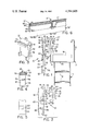
- FIG. 1 is a fragmentary, end view of a venetian blind and a strip support embodying the present invention which is mounted on the headrail of the blind;
- FIG. 2 is an exploded end view of the strip support illustrated in FIG. 1;
- FIG. 3 is a perspective view of a clip which is a component of said support
- FIG. 4 is a perspective view of a strip holder which is a component of said support
- FIG. 5 is a fragment of FIG. 2 located by the cutting line VI--VI therein;
- FIG. 6 is a perspective view of an alternative embodiment of the strip holder of FIG. 4.
- a valance 10 is releasably mounted on the headrail 11 of a venetian blind.
- the headrail 11 is channel-shaped and has spaced front and rear walls 12 and 13, respectively, which extend upwardly from opposite edges of a substantially horizontal bottom wall 15.
- An operating mechanism 16 is mounted on the bottom wall 15 within the headrail 11 and a tape ladder 17 which suspends a plurality of horizontal blind slats 18 from the headrail 11.
- the ladder 17 extends through nonillustrated openings in the bottom wall 15 and is operatively engaged with the mechanism 16 in a conventional and nonillustrated manner.
- An inward return bend 21 is provided in the upper edge of the front wall 12 of the headrail 11 at the top thereof, the free edge 22 of the front wall 12 being spaced rearwardly from the remainder of the front wall 12.
- the valance 10 includes one or more strip supports 20 comprising a strip holder 26, a clip 27 and, in this embodiment, a pair of elongated horizontally extending and substantially flat strips 28 and 29, which may be blind slats 18.
- the U-shaped clip 27 has spaced, downwardly extending front and rear legs 31 and 32, respectively, which are connected at their upper ends by a bight 33.
- the rear leg 32 of the clip 27 has a lower portion 36 which is offset toward the front leg 31.
- An upwardly facing shoulder 41 is provided on the inner side of the leg 32 near the upper edge of the portion 36. As shown in FIG. 1, the shoulder 41 is cooperable with the free edge 22 of the front wall 12 of the headrail 11 to resist accidental disengagement of the clip 27 from the front wall 12 of the headrail 11.
- the legs 31 and 32 and the bight 33 of the clip 27 have a degree of resilient flexibility to facilitate engagement with and disengagement from the front wall 12 of the headrail.
- a forwardly projecting flange 43 is provided on the front leg 31 of the clip 27 near the bight 33 and has a transversely extending, upwardly projecting ridge 44 at the end thereof remote from the front leg 31.
- a pair of horizontally spaced, frontwardly projecting abutments 46 and 47 are provided at the lower end of the front leg 31 of the clip 27 for a purpose described hereinafter.
- the strip holder 26 includes an upright, substantially flat face plate 48 having a substantially planar front surface 49.
- a pair of vertically spaced and horizontal flanges 51 and 52 project from the rear side of the face plate 48 near the top thereof, the space between the flanges 51 and 52 providing a rearwardly opening slot 50.
- a groove 53 is provided in the undersurface of the upper flange 51 adjacent to and parallel with the face plate 48.
- the slot 50 and flange 43 have L-shaped cross-sections which are interfitting and cooperate to releasably secure the holder 26 to the clip 27.
- a projection 56 extends rearwardly from the face plate 48 below the flanges 51 and 52, and has a width which is preferably slightly less than the distance between the abutments 46 and 47 on the clip 27, and said projection 56 is positioned to be received between said abutments when the flange 43 is snugly disposed in the slot 50.
- Top and bottom hook elements 61 and 62 are respectively secured on or near the top and bottom edges of the face plate 48.
- An intermediate hook element 63 is secured to the front surface 49 of the face plate 48 intermediate the top and bottom edges thereof.
- a horizontally extending recess 64 is provided in the front surface 49 of the face plate behind the intermediate hook element 63.
- the clip 27 is releasably connected to the strip holder 26 by inserting the flange 43 of the clip 27 into the horizontal slot 50, and the upwardly projecting ridge 44 on the flange 43 is received into the groove 53, as shown in FIG. 1.
- the resultant interlock resists disengagement of the clip 27 from the strip holder 26.
- the flanges 51 and 52 of the strip holder 26 are preferably resiliently flexible in order to facilitate insertion of the flange 43 therebetween.
- the hook elements 63 and 62 respectively grip around the upper and lower lateral edges of the elongated strip 29, which is bowed slightly by such engagement so that it is securely retained by the hook elements.
- the lower edge of the elongated strip 28 is received in the recess 64 behind the intermediate hook element 63.
- the upper edge of the elongated strip 28 is gripped by the hook element 61, the elongated strip 28 being bowed slightly to effect a secure retention thereof.
- strip support 20 While only one strip support 20 may be used, plural strip supports will normally be mounted at intervals along the headrail 11. Also, while two strips 28 and 29 are illustrated and described, it will be recognized that single, double-width strip, not shown, could be mounted between and gripped by the hook elements 61 and 62. In such case, the hook element 63 and recess 64 could be omitted.
- FIG. 5 illustrates an alternative strip holder 26' which is similar in several respects to the strip holder 26 of FIG. 4, and functionally equivalent parts are therefore designated by the same reference numerals with a prime (') added thereto.
- the face place 48' of the strip holder 26' is horizontally elongated, and the vertically spaced, rearwardly projecting flanges 51' and 52' near the top thereof preferably extend the full length of the strip holder 26'.
- Rearward projections 56' are provided at spaced intervals along the strip holder 26'.
- Top and bottom hook elements 61' and 62', and nonillustrated intermediate hook elements are secured to the face plate 48'.
- a horizontal recess 64' is provided in the front surface of the strip holder 26' and extends the full length thereof.
- the clips 27 and elongated strips 28, 29 utilized with the strip holder 26' may be identical to those described above with respect to the embodiment of FIGS. 1-4, and they cooperate with the strip holder 26' in substantially the same manner described above with respect to the strip holder 26.
Landscapes
- Engineering & Computer Science (AREA)
- Structural Engineering (AREA)
- Architecture (AREA)
- Civil Engineering (AREA)
- Blinds (AREA)
Abstract
Description
Claims (7)
Priority Applications (1)
| Application Number | Priority Date | Filing Date | Title |
|---|---|---|---|
| US06/293,906 US4384605A (en) | 1981-08-18 | 1981-08-18 | Valance support for headrail |
Applications Claiming Priority (1)
| Application Number | Priority Date | Filing Date | Title |
|---|---|---|---|
| US06/293,906 US4384605A (en) | 1981-08-18 | 1981-08-18 | Valance support for headrail |
Publications (1)
| Publication Number | Publication Date |
|---|---|
| US4384605A true US4384605A (en) | 1983-05-24 |
Family
ID=23131072
Family Applications (1)
| Application Number | Title | Priority Date | Filing Date |
|---|---|---|---|
| US06/293,906 Expired - Fee Related US4384605A (en) | 1981-08-18 | 1981-08-18 | Valance support for headrail |
Country Status (1)
| Country | Link |
|---|---|
| US (1) | US4384605A (en) |
Cited By (32)
| Publication number | Priority date | Publication date | Assignee | Title |
|---|---|---|---|---|
| US4475706A (en) * | 1981-11-27 | 1984-10-09 | Hunter Douglas Inc. | Overhead mounting bracket for a horizontal venetian blind assembly |
| US4662421A (en) * | 1985-12-03 | 1987-05-05 | Basmadji Mounir P | Universal valance assembly |
| US4772519A (en) * | 1986-03-19 | 1988-09-20 | J. Irvine, Inc. | Distance piece |
| US4828002A (en) * | 1987-06-22 | 1989-05-09 | Home Fashions, Inc. | Window covering headrail cornice |
| US4840216A (en) * | 1988-05-19 | 1989-06-20 | Home Fashions, Inc. | Valance bracket for a vertical blind |
| US4930562A (en) * | 1989-03-10 | 1990-06-05 | Hunter Douglas Inc. | Decoratively covered blind structure |
| US5033525A (en) * | 1990-06-04 | 1991-07-23 | Guenther Paeselt | Decorative curtain hanger |
| US5042548A (en) * | 1989-12-07 | 1991-08-27 | Home Fashions, Inc. | Cornice for a window covering headrail |
| US5188162A (en) * | 1991-12-18 | 1993-02-23 | Newell Operating Company | Mini blind system and valance assembly therefor |
| US5660219A (en) * | 1996-04-30 | 1997-08-26 | Cooper Industries, Inc. | Method and device for installing a cornice |
| US5803144A (en) * | 1995-07-25 | 1998-09-08 | Newval, Inc. | Multipurpose valance assembly |
| US5896909A (en) * | 1997-12-15 | 1999-04-27 | Kenney Manufacturing Company | Swag holder |
| USD418401S (en) * | 1999-02-16 | 2000-01-04 | Hunter Douglas Inc. | Valance clip for architectural coverings |
| US6145567A (en) * | 1999-07-29 | 2000-11-14 | Henley, Jr.; E. Patrick | Blind valance assembly and method |
| US6293330B1 (en) | 1999-08-26 | 2001-09-25 | Newell Window Furnishings, Inc. | Universal head rail |
| US6601809B1 (en) * | 2002-04-05 | 2003-08-05 | Robert Gebrara | Valance bracket for horizontal blinds |
| US6659154B2 (en) * | 2002-04-26 | 2003-12-09 | Isoteck Corporation | Valance with adjustable mounting features |
| US20050109902A1 (en) * | 2002-12-24 | 2005-05-26 | Chris Wolfe | Mounting bracket and headrail assembly |
| US20060175025A1 (en) * | 2005-02-10 | 2006-08-10 | Mcmenamin Tim | Blind/curtain mounting bracket for curtain rods |
| US20080169067A1 (en) * | 2007-01-17 | 2008-07-17 | Nien Made Enterprise Co. , Ltd. | Fixing device for a decorative plate of the top rail of a blind |
| US20090032200A1 (en) * | 2007-08-03 | 2009-02-05 | Nien Made Enterprise Co., Ltd | Adjustable hanging apparatus for blind valances |
| US20090078378A1 (en) * | 2007-09-21 | 2009-03-26 | Cecchetti Dag H | Privacy blind |
| US20100013728A1 (en) * | 2008-07-15 | 2010-01-21 | The Charles Machine Works, Inc. | Antenna Design |
| US20160255981A1 (en) * | 2015-03-04 | 2016-09-08 | Karen Rae | Fastener-less Bracket System |
| US9487998B1 (en) * | 2015-10-13 | 2016-11-08 | Danny Agudelo | Window blinds with solar panels |
| JP2017031624A (en) * | 2015-07-30 | 2017-02-09 | 立川ブラインド工業株式会社 | Hanger and solar shading device |
| US20170208980A1 (en) * | 2016-01-25 | 2017-07-27 | Current Products Corp. | Valance System For Window Coverings |
| US20180283093A1 (en) * | 2017-03-28 | 2018-10-04 | William Wei-Loon Tseng | Accessory of venetian blind |
| US20190271190A1 (en) * | 2018-03-05 | 2019-09-05 | Tser Wen Chou | Blind decorative board fixing support assembly |
| US10638815B2 (en) * | 2018-06-25 | 2020-05-05 | Taiwan Oasis Technology Co., Ltd. | Buckle joint structure |
| US20210270085A1 (en) * | 2019-04-16 | 2021-09-02 | William Alex Simms | Transom blind acces sory for venetian blinds and blinds formed with a transom |
| US20220235607A1 (en) * | 2021-01-26 | 2022-07-28 | Levolor, Inc. | Rail clips for stowing a tilt wand and related headrail assemblies and coverings |
Citations (7)
| Publication number | Priority date | Publication date | Assignee | Title |
|---|---|---|---|---|
| US1769727A (en) * | 1924-07-24 | 1930-07-01 | United Carr Fastener Corp | Snap fastener |
| US2588332A (en) * | 1946-11-22 | 1952-03-04 | Quaker Stretcher Company | Curtain stretcher |
| US2775010A (en) * | 1954-08-23 | 1956-12-25 | United Carr Fastener Corp | Panel fastening device |
| US3136357A (en) * | 1963-06-12 | 1964-06-09 | Levolor Lorentzen Inc | Venetian blind installation and components for obstructing the passage of light between the head channel of the blind and a soffit or the like |
| US3599918A (en) * | 1969-12-15 | 1971-08-17 | Charles B Patchett | Clip for decorative lights and the like |
| US4133507A (en) * | 1977-04-27 | 1979-01-09 | Comerco, Inc. | System for mounting storage units |
| US4222156A (en) * | 1977-12-22 | 1980-09-16 | Levolor Lorentzen, Inc. | Holder for supporting a valance at a venetian blind head |
-
1981
- 1981-08-18 US US06/293,906 patent/US4384605A/en not_active Expired - Fee Related
Patent Citations (7)
| Publication number | Priority date | Publication date | Assignee | Title |
|---|---|---|---|---|
| US1769727A (en) * | 1924-07-24 | 1930-07-01 | United Carr Fastener Corp | Snap fastener |
| US2588332A (en) * | 1946-11-22 | 1952-03-04 | Quaker Stretcher Company | Curtain stretcher |
| US2775010A (en) * | 1954-08-23 | 1956-12-25 | United Carr Fastener Corp | Panel fastening device |
| US3136357A (en) * | 1963-06-12 | 1964-06-09 | Levolor Lorentzen Inc | Venetian blind installation and components for obstructing the passage of light between the head channel of the blind and a soffit or the like |
| US3599918A (en) * | 1969-12-15 | 1971-08-17 | Charles B Patchett | Clip for decorative lights and the like |
| US4133507A (en) * | 1977-04-27 | 1979-01-09 | Comerco, Inc. | System for mounting storage units |
| US4222156A (en) * | 1977-12-22 | 1980-09-16 | Levolor Lorentzen, Inc. | Holder for supporting a valance at a venetian blind head |
Cited By (40)
| Publication number | Priority date | Publication date | Assignee | Title |
|---|---|---|---|---|
| US4475706A (en) * | 1981-11-27 | 1984-10-09 | Hunter Douglas Inc. | Overhead mounting bracket for a horizontal venetian blind assembly |
| US4662421A (en) * | 1985-12-03 | 1987-05-05 | Basmadji Mounir P | Universal valance assembly |
| US4772519A (en) * | 1986-03-19 | 1988-09-20 | J. Irvine, Inc. | Distance piece |
| US4828002A (en) * | 1987-06-22 | 1989-05-09 | Home Fashions, Inc. | Window covering headrail cornice |
| US4840216A (en) * | 1988-05-19 | 1989-06-20 | Home Fashions, Inc. | Valance bracket for a vertical blind |
| US4930562A (en) * | 1989-03-10 | 1990-06-05 | Hunter Douglas Inc. | Decoratively covered blind structure |
| US5042548A (en) * | 1989-12-07 | 1991-08-27 | Home Fashions, Inc. | Cornice for a window covering headrail |
| US5033525A (en) * | 1990-06-04 | 1991-07-23 | Guenther Paeselt | Decorative curtain hanger |
| US5188162A (en) * | 1991-12-18 | 1993-02-23 | Newell Operating Company | Mini blind system and valance assembly therefor |
| US5803144A (en) * | 1995-07-25 | 1998-09-08 | Newval, Inc. | Multipurpose valance assembly |
| US5660219A (en) * | 1996-04-30 | 1997-08-26 | Cooper Industries, Inc. | Method and device for installing a cornice |
| US5896909A (en) * | 1997-12-15 | 1999-04-27 | Kenney Manufacturing Company | Swag holder |
| USD418401S (en) * | 1999-02-16 | 2000-01-04 | Hunter Douglas Inc. | Valance clip for architectural coverings |
| US6145567A (en) * | 1999-07-29 | 2000-11-14 | Henley, Jr.; E. Patrick | Blind valance assembly and method |
| US6293330B1 (en) | 1999-08-26 | 2001-09-25 | Newell Window Furnishings, Inc. | Universal head rail |
| US6619366B2 (en) | 1999-08-26 | 2003-09-16 | Newell Window Furnishings, Inc. | Universal head rail |
| US6601809B1 (en) * | 2002-04-05 | 2003-08-05 | Robert Gebrara | Valance bracket for horizontal blinds |
| US6659154B2 (en) * | 2002-04-26 | 2003-12-09 | Isoteck Corporation | Valance with adjustable mounting features |
| US20050109902A1 (en) * | 2002-12-24 | 2005-05-26 | Chris Wolfe | Mounting bracket and headrail assembly |
| US7048028B2 (en) | 2002-12-24 | 2006-05-23 | Newell Window Furnishings, Inc. | Mounting bracket and headrail assembly |
| US20060175025A1 (en) * | 2005-02-10 | 2006-08-10 | Mcmenamin Tim | Blind/curtain mounting bracket for curtain rods |
| US7198088B2 (en) * | 2005-02-10 | 2007-04-03 | Mcmenamin Tim | Blind/curtain mounting bracket for curtain rods |
| US20070200040A1 (en) * | 2005-02-10 | 2007-08-30 | Mcmenamin Tim | Blind/curtain mounting bracket for curtain rods |
| US20080169067A1 (en) * | 2007-01-17 | 2008-07-17 | Nien Made Enterprise Co. , Ltd. | Fixing device for a decorative plate of the top rail of a blind |
| US20090032200A1 (en) * | 2007-08-03 | 2009-02-05 | Nien Made Enterprise Co., Ltd | Adjustable hanging apparatus for blind valances |
| US7730923B2 (en) * | 2007-08-03 | 2010-06-08 | Niem Made Enterprise Co., Ltd. | Adjustable hanging apparatus for blind valances |
| US20090078378A1 (en) * | 2007-09-21 | 2009-03-26 | Cecchetti Dag H | Privacy blind |
| US20100013728A1 (en) * | 2008-07-15 | 2010-01-21 | The Charles Machine Works, Inc. | Antenna Design |
| US8674894B2 (en) * | 2008-07-15 | 2014-03-18 | The Charles Machine Works, Inc. | Antenna design |
| US20160255981A1 (en) * | 2015-03-04 | 2016-09-08 | Karen Rae | Fastener-less Bracket System |
| JP2017031624A (en) * | 2015-07-30 | 2017-02-09 | 立川ブラインド工業株式会社 | Hanger and solar shading device |
| US9487998B1 (en) * | 2015-10-13 | 2016-11-08 | Danny Agudelo | Window blinds with solar panels |
| US20170208980A1 (en) * | 2016-01-25 | 2017-07-27 | Current Products Corp. | Valance System For Window Coverings |
| US10694880B2 (en) * | 2016-01-25 | 2020-06-30 | Current Products Corp. | Valance system for window coverings |
| US20180283093A1 (en) * | 2017-03-28 | 2018-10-04 | William Wei-Loon Tseng | Accessory of venetian blind |
| US20190271190A1 (en) * | 2018-03-05 | 2019-09-05 | Tser Wen Chou | Blind decorative board fixing support assembly |
| US10638815B2 (en) * | 2018-06-25 | 2020-05-05 | Taiwan Oasis Technology Co., Ltd. | Buckle joint structure |
| US20210270085A1 (en) * | 2019-04-16 | 2021-09-02 | William Alex Simms | Transom blind acces sory for venetian blinds and blinds formed with a transom |
| US12116839B2 (en) * | 2019-04-16 | 2024-10-15 | William Alex Simms | Transom blind accessory for venetian blinds and blinds formed with a transom |
| US20220235607A1 (en) * | 2021-01-26 | 2022-07-28 | Levolor, Inc. | Rail clips for stowing a tilt wand and related headrail assemblies and coverings |
Similar Documents
| Publication | Publication Date | Title |
|---|---|---|
| US4384605A (en) | Valance support for headrail | |
| US4254813A (en) | Valance bracket for vertical venetian blind | |
| US4840216A (en) | Valance bracket for a vertical blind | |
| US4828002A (en) | Window covering headrail cornice | |
| US5040750A (en) | Eavestrough hook and leaf guard | |
| US5039049A (en) | Rod and bracket assembly for window curtains and valances | |
| US6672359B2 (en) | Valance mounting system and method | |
| EP0726722B1 (en) | Shelf bracket assembly | |
| US7134469B2 (en) | Headrail mounting system | |
| US4662421A (en) | Universal valance assembly | |
| US3614045A (en) | Snap-in drapery brackets | |
| US4919185A (en) | Headrail and bracket combination for supporting blinds | |
| US5195570A (en) | Bracket for window covering assembly | |
| CA1169756A (en) | Support bracket | |
| GB2200531A (en) | Securing bracket for channel sections | |
| US6322029B1 (en) | Installation bracket | |
| US4824062A (en) | Curtain rod and end bracket assembly | |
| US6840482B2 (en) | Mounting bracket for curtain rods | |
| US4399856A (en) | Adjustable valance suspension bracket | |
| JPH0645951B2 (en) | Lattice ceiling | |
| US4254814A (en) | Venetian blind and a valance bracket therefor | |
| US2706521A (en) | Fascia board and curtain rod mounting bracket | |
| CA2513393C (en) | Bracket rail for window coverings | |
| US2524711A (en) | Venetian blind installation bracket | |
| US5188162A (en) | Mini blind system and valance assembly therefor |
Legal Events
| Date | Code | Title | Description |
|---|---|---|---|
| AS | Assignment |
Owner name: COOPER INDUSTRIES, INC., STE. 2700, TWO HOUSTON CE Free format text: ASSIGNMENT OF ASSIGNORS INTEREST.;ASSIGNORS:SCHAEFFER, BRUCE W.;BROTHERS, MICHAEL V.;REEL/FRAME:003910/0994 Effective date: 19810804 |
|
| MAFP | Maintenance fee payment |
Free format text: PAYMENT OF MAINTENANCE FEE, 4TH YEAR, PL 96-517 (ORIGINAL EVENT CODE: M170); ENTITY STATUS OF PATENT OWNER: LARGE ENTITY Year of fee payment: 4 |
|
| FEPP | Fee payment procedure |
Free format text: PAYOR NUMBER ASSIGNED (ORIGINAL EVENT CODE: ASPN); ENTITY STATUS OF PATENT OWNER: LARGE ENTITY |
|
| MAFP | Maintenance fee payment |
Free format text: PAYMENT OF MAINTENANCE FEE, 8TH YEAR, PL 96-517 (ORIGINAL EVENT CODE: M171); ENTITY STATUS OF PATENT OWNER: LARGE ENTITY Year of fee payment: 8 |
|
| FEPP | Fee payment procedure |
Free format text: MAINTENANCE FEE REMINDER MAILED (ORIGINAL EVENT CODE: REM.); ENTITY STATUS OF PATENT OWNER: LARGE ENTITY |
|
| LAPS | Lapse for failure to pay maintenance fees | ||
| FP | Lapsed due to failure to pay maintenance fee |
Effective date: 19950524 |
|
| STCH | Information on status: patent discontinuation |
Free format text: PATENT EXPIRED DUE TO NONPAYMENT OF MAINTENANCE FEES UNDER 37 CFR 1.362 |