US4356085A - Rotary screening machine for pulp suspensions - Google Patents
Rotary screening machine for pulp suspensions Download PDFInfo
- Publication number
- US4356085A US4356085A US06/236,626 US23662681A US4356085A US 4356085 A US4356085 A US 4356085A US 23662681 A US23662681 A US 23662681A US 4356085 A US4356085 A US 4356085A
- Authority
- US
- United States
- Prior art keywords
- machine
- drum
- vanes
- screening slot
- impurities
- Prior art date
- Legal status (The legal status is an assumption and is not a legal conclusion. Google has not performed a legal analysis and makes no representation as to the accuracy of the status listed.)
- Expired - Lifetime
Links
Images


Classifications
-
- B—PERFORMING OPERATIONS; TRANSPORTING
- B07—SEPARATING SOLIDS FROM SOLIDS; SORTING
- B07B—SEPARATING SOLIDS FROM SOLIDS BY SIEVING, SCREENING, SIFTING OR BY USING GAS CURRENTS; SEPARATING BY OTHER DRY METHODS APPLICABLE TO BULK MATERIAL, e.g. LOOSE ARTICLES FIT TO BE HANDLED LIKE BULK MATERIAL
- B07B1/00—Sieving, screening, sifting, or sorting solid materials using networks, gratings, grids, or the like
- B07B1/18—Drum screens
- B07B1/20—Stationary drums with moving interior agitators
-
- D—TEXTILES; PAPER
- D21—PAPER-MAKING; PRODUCTION OF CELLULOSE
- D21D—TREATMENT OF THE MATERIALS BEFORE PASSING TO THE PAPER-MAKING MACHINE
- D21D5/00—Purification of the pulp suspension by mechanical means; Apparatus therefor
- D21D5/02—Straining or screening the pulp
- D21D5/023—Stationary screen-drums
- D21D5/026—Stationary screen-drums with rotating cleaning foils
Definitions
- the present invention relates to a rotary screening machine for pulp suspension that is contaminated with impurities.
- the invention relates to means in the machine, and particularly the sorting and conveying vanes, for causing the suspension and particles therein to pulsatingly move across the screen, preventing particle build-up on the screen.
- a rotary screening machine of the type with which the invention is employed comprises a rotating drum, an annular basket like screen around the drum, an annular screen slot or space defined between the drum and the screen and sorting means in the screen slot, e.g. supported on the drum, for moving the suspension axially along the screen slot and for also sorting out the desirable particles and the rejected impurities, so that the former and latter materials may pass to respective collection areas.
- the object of the present invention is to obtain good separation of the components of a fiber suspension in a screening machine with the use of as little power as possible.
- Another object of the invention is to cause pulsation of the suspension and its components radially across the screen, for reducing screen clogging.
- a further object is to improve axial conveyance of the suspension.
- the projections on the drum are sorting vanes projecting radially outwardly from the drum. Starting at what is the leading edge of each vane during rotation, the top and bottom surfaces of the vane taper wider in the direction of the axis of the drum in a generally wedge shape.
- the vane profile is of wedge shape and thus has only a low coefficient of resistance so that the acceleration of the suspension by the vanes, particularly in the circumferential direction, is rather small.
- the screening machine operates with relatively low consumption of power. Spinning of the components of the suspension of the vanes can also easily be avoided in that the leading edge of the vanes (as seen in the direction of rotation) are slightly beveled rearwardly.
- the screening machine is of simple construction and is easy to manufacture. By simply turning of the vanes on a lathe, the screen slot which is to be maintained between the radially outer edge of the vanes and the screen basket can be produced relatively simply.
- the development and arrangement of the sorting vanes in accordance with the invention is also favorable in that it substantially eliminates the detrimental effects that might be caused by pulsations through the use of a relatively large number of vanes, since the pulsations are then of only slight amplitude.
- At least one of the wedge surfaces that defines the sorting vane is inclined from the horizontal, i.e. from a plane perpendicular to the axis of the drum, along the radial direction of extension of the vane to produce additional conveyance momentum components of the fiber suspension with respect to the screen basket.
- each vane may cooperate to give the vane a generally "V" shaped profile, widening from the leading to the trailing ends of the vane.
- An open space is defined between the wedge surfaces of a vane and a vacuum develops there as the drum rotates.
- An additional lateral wall may be positioned in that open space, extending between the upper and lower wedge surfaces and also extending rearwardly from the leading edge of the vane, to control the size and shape of that space between the wedge surfaces that faces radially outwardly toward the screen basket. The orientation and position of this wall will cooperate in determining the direction of pulsation of the fiber suspension as each vane rotates past.
- that wall is shaped, oriented and positioned so that both the radial and axial length of the space between the wedge surfaces gradually increases from the leading edge of the vane to the trailing edge thereof.
- Various other orientations of the limiting wall are possible, including an orientation where it is radially closer to the screen basket near the leading edge than at the trailing edge of the vane, or vice versa.
- the wall orientation selected depends upon the particular pressure-vacuum condition that is sought to be established there.
- the drum has diluting liquid spray holes, i.e. water spray holes, defined in it.
- the generally porous screen basket Opposed to the spray holes, the generally porous screen basket has no openings through it, thereby confining the sprayed diluting water within the screen slot.
- the drum may have different axial zones, with the sorting vanes being nearer the lower zone and the upper zone not having vanes of the type described above.
- the sorting vanes are configured to axially move the suspension in a manner calculated to cause the above described separation.
- FIG. 1 is an axial sectional view showing a first embodiment of a rotary screening machine in accordance with the invention, which is of open, unpressurized construction;
- FIG. 1a is a partial axial sectional view through the sorting drum like that of FIG. 1, shown on a large scale;
- FIGS. 2 and 3 are the same type of view as FIG. 1 respectively showing further embodiments of screening machines;
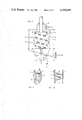
- FIG. 4 is a partial radial sectional view through one modified embodiment of a sorting drum, on a larger scale
- FIG. 5 is a partial axial sectional view through an embodiment of a sorting drum, on a larger scale but also showing features of the embodiment of FIG. 4;
- FIG. 6 is a similar sectional view to FIG. 5 showing yet another embodiment of a sorting drum
- FIGS. 7a to 7c are views corresponding respectively to FIGS. 4-6 showing still another embodiment of a sorting drum.
- FIG. 8 shows a screening machine according to the invention with a different embodiment of a drum.
- a rotary screening machine includes an outer housing 20.
- An annular, cylindrical drum 1 is rotatably supported in the housing 20 and rotates about is axis with a constant radius annular screen slot 3 within an annular screen basket 2.
- the constant radius of the slot 3 is defined between the periphery of the drum 1 and the screen basket 2.
- the drum has end walls 41 and 42 at its respective axial ends.
- the shaft 39 supports the drum 1 for rotation.
- the shaft 39 is supported horizontally in the lower part of the housing 20 in a bearing (not shown).
- the shaft 39 is driven to rotate by the belt 38, via drive pulleys 36 and 37.
- the pulley 36 may be fastened to the shaft, for instance, of an electric motor (not shown).
- Fiber suspension to be sorted is fed from below, through the feed connection 6, directly into the screen slot 3 between the drum 1 and the screen basket 2.
- the suspension is picked up in the slot 3 by the rotating vanes 4 which are fastened to the shell of the rotatable drum 1.
- the suspension is conveyed along the screen slot 3 in the axial direction to the rejects outlet 12 located at the upper end of the drum.
- the properly divided, cleaned pulp passes through the holes or pores along the length of the screen basket 2, and the pulp piles up in the housing 20 to a certain height and then discharges radially through an accepted pulp outlet 17.
- the rejected material passes tangentially out of the sorter at the upper end of the screen slot 3, through a chute 12.
- the rotor, or drum 1 carries sorting vanes 4 and 40 projecting from its surface. Vanes 40 are described below.
- Each sorting vane 4 on the drum 1 is generally of wedge shape, tapering gradually wider, measured axially of the drum, rearwardly from the narrow leading edge 11 of the vane.
- Each vane 4 has an upper, upwardly inclined, wedge surface 10 and a lower, downwardly inclined, wedge surface 9. The direction of the inclines just mentioned is rearwardly with respect to the direction of rotation of the drum.
- Each vane 4 is defined by thin plates defining wedge surfaces 9 and 10, which thereby defines an open volume between the wedge surfaces 9 and 10.
- both the sorting vanes 4 and the vanes 40 are arranged somewhat in a helical array around the drum 1. But, the sorting vanes 4 are helically arranged to an extent that they do not cause an excessive axial conveyance component of the fiber suspension along the screen slot 3 to the rejects outlet 12. In practice, the vanes 4 are staggered somewhat with respect to each other, so that their lower wedge surfaces 9 also strike a part of the suspension upon the rotation of the drum 1.
- the lower wedge surfaces 9 of the vanes are inclined downwardly with increasing distance rearwardly from the leading edges 11 of the vanes.
- the lower wedge surfaces incline upwardly from the horizontal (or from a plane perpendicular to the axis of the drum 1), moving radially outwardly of the drum 1.
- This inclination of the surfaces 9 of the vanes causes a component of motion of the particles impinging upon the vanes which is directed toward the screen 2.
- the particles that were initially drawn away from the screen 2 by the vacuum produced by the rotating vanes are again conveyed against the screen, which increases the possibility that particles of acceptable quality pulp can be sorted through the holes in the screen 2.
- a ring of impurities 15 that forms in the uppermost zone of the screen slot 3 should consist predominantly of rejects or impurities.
- the lowermost region is provided with above described sorting vanes 4. Adjoining the lower region is a more central axial region of the rotor drum on which other sorting vanes 40 are present.
- the vanes 40 may either be so inclined on their lower wedge surfaces 9 that their suspension conveying action away from the rejects outlet 12 is less than in the case of the other vanes 4, or the lower wedge surfaces 9 of these vanes 40 are to be narrower in the radial direction starting from the surface of the drum, as can be noted from FIG. 1, than the upper wedge surfaces 10 of either of the sorting vanes 4 or 40.
- the upper, third region 30 of the rotor drum is smooth, i.e it is developed substantially without sorting vanes 4 or 40, and it lies predominantly above the screening zone, or screen slot 3. This is necessary to permit concentrating of the rejects 15. This produces reject consistencies of 20 to 25% and more, by volume of solid to liquid materials, at the rejects outlet.
- the rotor drum 1 is provided with reaming vanes 45 at its upper end.
- Spray holes 8 for pulp diluent i.e. water
- the other spray holes for dilution water 8 lie in an axially central region along the rotor drum 1, opposite a nonporous section of the screen basket 2 where there are no sorting holes or slots. With relatively little spray water, the screen 2 is kept suitably free of fibers by dilution of the suspension. It is also preferred to provide the region of the screen basket 2 lying below the spray holes 8 with relatively large screen perforations of, for instance, 6 mm diameter as compared with screen perforations in the upper region of about 4 mm diameter.
- FIG. 8 shows a screening machine construction having a different division of zones.
- the drum and screen slot 3 are developed with three zones in this embodiment.
- the drum 1 carries the sorting vanes 4.
- the drum In the adjoining zone above, the drum carries vanes 5, which serve predominantly for the transport of the rejects toward the upper, outlet end of the sorter.
- the rotor 1 In the top zone 30, the rotor 1 is smooth, being without projections, vanes or the like. In this zone, the rejects residue is to be held back, so that too rapid a passage thereof through the rotor, with too low a separating effect of the acceptable quality pulp, is avoided.
- a spray-water feed with a spray-water connection head 14 is provided in the inside of the drum 1 for diluting the suspension, again by means of spray water flowing through the spray openings 8.
- the openings are arranged predominatly in the axially central part of the rotor. But, these openings may extend into the second, central zone and even to the third upper zone, in order to still make it possible to separate the acceptable pulp even in the upper region of the apparatus.
- the open or unpressurized construction of a screening machine described above is suitable particularly as a final stage screener for the various screening residue which collect in a paper mill, including waste paper.
- a high consistency of rejects is obtainable, particularly with the embodiment in accordance with FIG. 1.
- the wall 19 can be oriented to increase or decrease the volume of the space 7 between the surfaces 10 moving rearwardly from the leading end 11, or vice versa.
- the wall 19 between the upper and lower surfaces of the vanes 4 also stiffens the vanes so that the wall thickness supporting surfaces 9 and 10 can be reduced.
- the wall extends from the leading end 11 to the trailing end. Although the wall may simply terminate at the trailing end, it instead turns radially inwardly along the trailing edge of the vane 4 at 19a, so that the volume radially inward of the wall 19 is enclosed and does not directly provide a force component to the suspension.
- the screen slot 3 can be made relatively narrow so that a relatively low conveying energy is required.
- a narrow radius annular screen slot 3 is also helpful for assuring that sorting takes place essentially only in the immediate vicinity of the screen 2, while an unnecessarily large screening slot 3, i.e. one with a large radial size can only be disadvantageous.
- substantially vertically extending ledges may be fastened to the inner wall of the screen 2 for producing despecking, in that the vanes which pass closely along the screen (or the ledges) break down the specks present in the fiber suspension.
- Feeding of the fiber suspension in this embodiment operates as with the embodiment of FIG. 5.
- This embodiment is used predominantly for the closed, pressurized construction, with the type of drum in accordance with FIG. 2, and also without the division thereof into zones.
- the closed construction as illustrated in FIG. 2 closes the housing by a bottom plate.
- the lower part of the housing includes a socket for the discharge of the rejects, corresponding to the socket 17 provided for the discharge of the accepted suspension.
- the screening machine provides passage of the rejects from the top to the bottom with respect to the axial component of their movement.
- the sorting residue which collects in the screen slot 3 and which would already be relatively strongly concentrated, can be diluted with spray water coming from spray holes 8 in the shell of the drum, and this helps achieve a further sorting out of accepts.
- the spray water is fed into the interior of the drum 1 via a spray water connecting head 14 which is sealed against the stationary housing of the screening machine, generally at a housing lid, and the hollow drum shaft or a shaft-like connection of the drum, similar to FIGS. 1 to 3.
- a weir or damming wall 23 is provided, through the lower part 1a of the drum being made of a larger diameter than the upper part 1b of the drum.
- An overflow is provided for the upper part 1b of the drum, and the purified suspension is dammed up by a weir wall 22.
- a socket 18 the good pulp then emerges after the first or upper zone.
- Still another embodiment of a pressure screening machine of closed pressurized construction is possible with, however, the screening of the good quality pulp taking place radially inwarly into the screen slot 3.
- the feeding of the fiber suspension would be radially inward from the outside of the screen basket 2 toward the screen slot.
- the various embodiments of the rotary screening machine produce extremely favorable action, since the development and attachment of a mat of fibers on the screen basket 2 is prevented by the pulsating movement of the pulp across the screen basket. Clogging of the screen holes, starting from the attachment of particles of pulp at one point, namely from the side of the holes facing the direction of rotation, to an ever-increasing extent by the continuous addition of further particles which deposit there, is prevented by the pulsating movement, which repeatedly changes the direction of attack of the particles and the suspension against the screen and its holes. This makes it possible, to an increased extent, for very long fibers of the good pulp to be able to pass through the screen holes. The tendency of these fibers is to align themselves in the circumferential direction, which would substantially prevent passage through the screen holes.
- the invention avoids this. Due to the low coefficient of resistance of the sorting vanes and in the case of the open unpressurized construction of screening machine, the good conveying action within a relatively narrow screening slot, furthermore only little drive power is required for the conveying of the fiber suspension.
Landscapes
- Engineering & Computer Science (AREA)
- Mechanical Engineering (AREA)
- Paper (AREA)
- Combined Means For Separation Of Solids (AREA)
- Filtration Of Liquid (AREA)
- Separation Of Solids By Using Liquids Or Pneumatic Power (AREA)
- Treatment Of Liquids With Adsorbents In General (AREA)
- Separation Of Suspended Particles By Flocculating Agents (AREA)
- Unwinding Webs (AREA)
- Storage Of Web-Like Or Filamentary Materials (AREA)
Applications Claiming Priority (2)
| Application Number | Priority Date | Filing Date | Title |
|---|---|---|---|
| DE3006482 | 1980-02-21 | ||
| DE3006482A DE3006482C2 (de) | 1980-02-21 | 1980-02-21 | Rotationssortierer |
Publications (1)
| Publication Number | Publication Date |
|---|---|
| US4356085A true US4356085A (en) | 1982-10-26 |
Family
ID=6095183
Family Applications (1)
| Application Number | Title | Priority Date | Filing Date |
|---|---|---|---|
| US06/236,626 Expired - Lifetime US4356085A (en) | 1980-02-21 | 1981-02-20 | Rotary screening machine for pulp suspensions |
Country Status (8)
| Country | Link |
|---|---|
| US (1) | US4356085A (de) |
| EP (1) | EP0034780B1 (de) |
| JP (1) | JPS56133009A (de) |
| AT (1) | ATE24218T1 (de) |
| BR (1) | BR6100221U (de) |
| CA (1) | CA1174203A (de) |
| DE (2) | DE3006482C2 (de) |
| ES (1) | ES8206707A1 (de) |
Cited By (19)
| Publication number | Priority date | Publication date | Assignee | Title |
|---|---|---|---|---|
| US4832832A (en) * | 1984-12-25 | 1989-05-23 | Mitsubishi Jukogyo Kabushiki Kaisha | Pressure type slit screen |
| US4911828A (en) * | 1987-02-07 | 1990-03-27 | J.M. Voith Gmbh | Rejects sorting apparatus |
| US5000842A (en) * | 1987-04-30 | 1991-03-19 | A. Ahlstrom Corporation | Method and apparatus for treating fiber suspension |
| DE3935151A1 (de) * | 1989-10-21 | 1991-04-25 | Voith Gmbh J M | Rotor fuer einen sortierer zur wiedergewinnung von fasern aus papier oder zellstoff |
| US5078878A (en) * | 1988-03-07 | 1992-01-07 | Bird Escher Wyss | Pressure knotter screening apparatus |
| US5103842A (en) * | 1990-08-14 | 1992-04-14 | Philip Morris Incorporated | Conditioning cylinder with flights, backmixing baffles, conditioning nozzles and air recirculation |
| US5143220A (en) * | 1990-11-08 | 1992-09-01 | Ingersoll-Rand Company | Apparatus for screening to remove knots from a fluid borne slurry of fibers and knots |
| US5176261A (en) * | 1990-01-06 | 1993-01-05 | Hermann Finckh Maschinenfabrik Gmbh & Co. | Rotor for pressure sorters for sorting fibrous suspensions |
| US5190160A (en) * | 1991-08-02 | 1993-03-02 | Ingersoll-Rand Company | Method and apparatus for enhancing transport of knots in a knot drainer |
| US5255788A (en) * | 1991-07-12 | 1993-10-26 | J. M. Voith Gmbh | Pressure sorter |
| US5307939A (en) * | 1992-07-13 | 1994-05-03 | Ingersoll-Rand Company | Screening apparatus for papermaking pulp |
| WO1994023848A1 (en) * | 1993-04-15 | 1994-10-27 | Ingersoll-Rand Company | Screening apparatus for papermaking pulp |
| NL1009609C2 (nl) * | 1998-07-10 | 2000-01-11 | Constructie En Systeembouw Ver | Inrichting voor het scheiden van vaste deeltjes uit een in hoofdzaak uit vloeistof bestaande substantie. |
| DE19911884A1 (de) * | 1999-03-17 | 2000-09-21 | Voith Sulzer Papiertech Patent | Drucksortierer zum Sieben einer Papierfaserstoffsuspension und Siebräumer für einen solchen |
| US20050045529A1 (en) * | 2003-09-02 | 2005-03-03 | Gl&V Management Hungary Kft | Vortex inducing rotor for screening apparatus for papermaking pulp |
| US20150033573A1 (en) * | 2011-10-27 | 2015-02-05 | Kwan Heum Sim | Dehydrator |
| US9895719B2 (en) | 2013-01-10 | 2018-02-20 | Günther Holding GmbH & Co. KG | Sorting element for a sorting device |
| GB2600430A (en) * | 2018-08-01 | 2022-05-04 | Salvtech Ltd | Dry separation waste processing and apparatus for achieving such |
| US12139852B2 (en) | 2020-02-14 | 2024-11-12 | Taizen Co., Ltd. | Wet pulp material processing machine |
Families Citing this family (12)
| Publication number | Priority date | Publication date | Assignee | Title |
|---|---|---|---|---|
| DE3503241A1 (de) * | 1985-01-31 | 1986-08-07 | J.M. Voith Gmbh, 7920 Heidenheim | Sortierer, insbesondere vertikalsichter |
| SE443007B (sv) * | 1985-03-04 | 1986-02-10 | Kamyr Ab | Silanordning |
| DE3701400A1 (de) * | 1986-02-18 | 1987-10-08 | Voith Gmbh J M | Sortiereinrichtung fuer fasersuspensionen |
| DE3701669A1 (de) * | 1987-01-22 | 1988-08-04 | Voith Gmbh J M | Sortierfluegel |
| DE3831845A1 (de) * | 1988-09-19 | 1990-04-12 | Voith Gmbh J M | Sortiereinrichtung fuer fasersuspensionen |
| US5172813A (en) * | 1989-05-17 | 1992-12-22 | A. Ahlstrom Corporation | Method and an apparatus for treating fiber suspension |
| JPH0748715Y2 (ja) * | 1989-12-08 | 1995-11-08 | 株式会社サトミ製作所 | 紙料精選装置 |
| FR2666598B1 (fr) * | 1990-09-10 | 1994-05-27 | Escher Wyss Gmbh | Procede de separation, notamment de tri ou de fractionnement d'une suspension de pate a papier. |
| FI88414C (fi) * | 1991-01-30 | 1993-05-10 | Ahlstroem Oy | Anordning foer behandling av fibersuspension |
| FI92227C (fi) * | 1992-04-23 | 1994-10-10 | Ahlstroem Oy | Laite kuitususpension käsittelemiseksi |
| DE202014100802U1 (de) * | 2014-02-21 | 2015-05-22 | Stf Maschinen- Und Anlagenbau Gmbh | Vorrichtung zum Waschen von Schüttgut |
| CN113245197A (zh) * | 2021-05-20 | 2021-08-13 | 福建师范大学 | 一种生物反应和生物分离装置 |
Citations (17)
| Publication number | Priority date | Publication date | Assignee | Title |
|---|---|---|---|---|
| DE130871C (de) * | ||||
| US1533410A (en) * | 1921-03-28 | 1925-04-14 | Anton J Haug | Pulp-screening machine |
| US1670473A (en) * | 1925-05-23 | 1928-05-22 | Milne Samuel | Mechanical screen, strainer, and the like |
| US1722874A (en) * | 1928-01-13 | 1929-07-30 | Harold D Wells | Pulp screen |
| US1921750A (en) * | 1931-04-01 | 1933-08-08 | Carl Nebrich | Centrifugal separator for straining pulpy material, such as wood pulp, cellulose, paper pulp, and the like |
| US2337113A (en) * | 1941-10-22 | 1943-12-21 | Wilfred B Mathewson | Pulp screen |
| US2738065A (en) * | 1951-01-04 | 1956-03-13 | Mahlkuch Eva | Method of and apparatus for processing materials |
| US3149065A (en) * | 1961-12-21 | 1964-09-15 | Lummus Cotton Gin Co | Apparatus for separting air and trash from seed cotton |
| US3235087A (en) * | 1962-10-08 | 1966-02-15 | Brown Citrus Machinery Corp | Apparatus for separation of liquids from solids |
| US3247965A (en) * | 1963-05-07 | 1966-04-26 | Kimberly Clark Co | Vertical centrifugal screen for pulp stock |
| US3303759A (en) * | 1964-05-11 | 1967-02-14 | Peters Leo | Converting machine for butter patty plate |
| US3404065A (en) * | 1966-12-01 | 1968-10-01 | Karlstad Mekaniska Ab | Apparatus for cleaning and fractionating a pulp suspension |
| US3458038A (en) * | 1966-06-02 | 1969-07-29 | Ingersoll Rand Canada | Screening apparatus |
| US3898157A (en) * | 1973-03-23 | 1975-08-05 | Hooper & Co Ltd S W | Two stage pressure pulp screen device with stationary cylindrical screen |
| US3964996A (en) * | 1974-03-20 | 1976-06-22 | Hermann Finckh Metalltuch- Und Maschinenfabrik | Classifying unit for fibrous suspensions |
| US4200537A (en) * | 1977-11-23 | 1980-04-29 | E. Et M. Lamort | Apparatus for the purification of paper pulp |
| US4202761A (en) * | 1977-03-23 | 1980-05-13 | Hermann Finckh Maschinenfabrik | Sorting apparatus for sorting fiber suspensions |
Family Cites Families (8)
| Publication number | Priority date | Publication date | Assignee | Title |
|---|---|---|---|---|
| DE495284C (de) * | 1925-05-23 | 1930-04-04 | Samuel Milne | Verfahren und Einrichtung zum Sichten von Papierstoff u. dgl. |
| GB336252A (en) * | 1929-07-04 | 1930-10-06 | Siliam Martin Bjerre | Improvements in screens |
| DE579606C (de) * | 1931-04-02 | 1933-06-29 | Carl Nebrich | Schleudersichter fuer Holzschliff, Zellstoff, Papierstoff u. dgl. |
| US3363759A (en) * | 1964-04-29 | 1968-01-16 | Bird Machine Co | Screening apparatus with rotary pulsing member |
| US4165841A (en) * | 1975-10-30 | 1979-08-28 | J. M. Voith Gmbh | Apparatus for separating contaminants from fibrous suspensions |
| DE2712715B2 (de) * | 1977-03-23 | 1979-05-23 | Hermann Finckh Maschinenfabrik Gmbh & Co, 7417 Pfullingen | Sortierer für Fasersuspensionen |
| DE2850385C2 (de) * | 1978-11-21 | 1981-02-05 | J.M. Voith Gmbh, 7920 Heidenheim | Vorrichtung zum Ausscheiden von Verunreinigungen aus Faserstoffsuspensionen |
| FR2461060A1 (fr) * | 1979-07-06 | 1981-01-30 | Lamort E & M | Dispositif pour l'epuration et la recuperation de pate a papier |
-
1980
- 1980-02-21 DE DE3006482A patent/DE3006482C2/de not_active Expired
-
1981
- 1981-02-14 EP EP81101042A patent/EP0034780B1/de not_active Expired
- 1981-02-14 AT AT81101042T patent/ATE24218T1/de not_active IP Right Cessation
- 1981-02-14 DE DE8181101042T patent/DE3175705D1/de not_active Expired
- 1981-02-16 BR BR6100221U patent/BR6100221U/pt unknown
- 1981-02-20 CA CA000371380A patent/CA1174203A/en not_active Expired
- 1981-02-20 US US06/236,626 patent/US4356085A/en not_active Expired - Lifetime
- 1981-02-20 ES ES499618A patent/ES8206707A1/es not_active Expired
- 1981-02-21 JP JP2482781A patent/JPS56133009A/ja active Granted
Patent Citations (17)
| Publication number | Priority date | Publication date | Assignee | Title |
|---|---|---|---|---|
| DE130871C (de) * | ||||
| US1533410A (en) * | 1921-03-28 | 1925-04-14 | Anton J Haug | Pulp-screening machine |
| US1670473A (en) * | 1925-05-23 | 1928-05-22 | Milne Samuel | Mechanical screen, strainer, and the like |
| US1722874A (en) * | 1928-01-13 | 1929-07-30 | Harold D Wells | Pulp screen |
| US1921750A (en) * | 1931-04-01 | 1933-08-08 | Carl Nebrich | Centrifugal separator for straining pulpy material, such as wood pulp, cellulose, paper pulp, and the like |
| US2337113A (en) * | 1941-10-22 | 1943-12-21 | Wilfred B Mathewson | Pulp screen |
| US2738065A (en) * | 1951-01-04 | 1956-03-13 | Mahlkuch Eva | Method of and apparatus for processing materials |
| US3149065A (en) * | 1961-12-21 | 1964-09-15 | Lummus Cotton Gin Co | Apparatus for separting air and trash from seed cotton |
| US3235087A (en) * | 1962-10-08 | 1966-02-15 | Brown Citrus Machinery Corp | Apparatus for separation of liquids from solids |
| US3247965A (en) * | 1963-05-07 | 1966-04-26 | Kimberly Clark Co | Vertical centrifugal screen for pulp stock |
| US3303759A (en) * | 1964-05-11 | 1967-02-14 | Peters Leo | Converting machine for butter patty plate |
| US3458038A (en) * | 1966-06-02 | 1969-07-29 | Ingersoll Rand Canada | Screening apparatus |
| US3404065A (en) * | 1966-12-01 | 1968-10-01 | Karlstad Mekaniska Ab | Apparatus for cleaning and fractionating a pulp suspension |
| US3898157A (en) * | 1973-03-23 | 1975-08-05 | Hooper & Co Ltd S W | Two stage pressure pulp screen device with stationary cylindrical screen |
| US3964996A (en) * | 1974-03-20 | 1976-06-22 | Hermann Finckh Metalltuch- Und Maschinenfabrik | Classifying unit for fibrous suspensions |
| US4202761A (en) * | 1977-03-23 | 1980-05-13 | Hermann Finckh Maschinenfabrik | Sorting apparatus for sorting fiber suspensions |
| US4200537A (en) * | 1977-11-23 | 1980-04-29 | E. Et M. Lamort | Apparatus for the purification of paper pulp |
Cited By (23)
| Publication number | Priority date | Publication date | Assignee | Title |
|---|---|---|---|---|
| US4832832A (en) * | 1984-12-25 | 1989-05-23 | Mitsubishi Jukogyo Kabushiki Kaisha | Pressure type slit screen |
| US4911828A (en) * | 1987-02-07 | 1990-03-27 | J.M. Voith Gmbh | Rejects sorting apparatus |
| US5000842A (en) * | 1987-04-30 | 1991-03-19 | A. Ahlstrom Corporation | Method and apparatus for treating fiber suspension |
| US5078878A (en) * | 1988-03-07 | 1992-01-07 | Bird Escher Wyss | Pressure knotter screening apparatus |
| DE3935151C2 (de) * | 1989-10-21 | 1998-09-17 | Voith Gmbh J M | Rotor für einen Sortierer zur Wiedergewinnung von Fasern aus Papier oder Zellstoff |
| DE3935151A1 (de) * | 1989-10-21 | 1991-04-25 | Voith Gmbh J M | Rotor fuer einen sortierer zur wiedergewinnung von fasern aus papier oder zellstoff |
| US5176261A (en) * | 1990-01-06 | 1993-01-05 | Hermann Finckh Maschinenfabrik Gmbh & Co. | Rotor for pressure sorters for sorting fibrous suspensions |
| US5103842A (en) * | 1990-08-14 | 1992-04-14 | Philip Morris Incorporated | Conditioning cylinder with flights, backmixing baffles, conditioning nozzles and air recirculation |
| US5143220A (en) * | 1990-11-08 | 1992-09-01 | Ingersoll-Rand Company | Apparatus for screening to remove knots from a fluid borne slurry of fibers and knots |
| US5255788A (en) * | 1991-07-12 | 1993-10-26 | J. M. Voith Gmbh | Pressure sorter |
| US5190160A (en) * | 1991-08-02 | 1993-03-02 | Ingersoll-Rand Company | Method and apparatus for enhancing transport of knots in a knot drainer |
| US5307939A (en) * | 1992-07-13 | 1994-05-03 | Ingersoll-Rand Company | Screening apparatus for papermaking pulp |
| US5497886A (en) * | 1992-07-13 | 1996-03-12 | Ingersoll-Rand Company | Screening apparatus for papermaking pulp |
| WO1994023848A1 (en) * | 1993-04-15 | 1994-10-27 | Ingersoll-Rand Company | Screening apparatus for papermaking pulp |
| NL1009609C2 (nl) * | 1998-07-10 | 2000-01-11 | Constructie En Systeembouw Ver | Inrichting voor het scheiden van vaste deeltjes uit een in hoofdzaak uit vloeistof bestaande substantie. |
| EP0971067A1 (de) * | 1998-07-10 | 2000-01-12 | RainboWW B.V. | Vorrichtung zum Abtrennen von Feststoffpartikeln aus einem Medium, das hauptsächlich aus einer Flüssigkeit besteht |
| DE19911884A1 (de) * | 1999-03-17 | 2000-09-21 | Voith Sulzer Papiertech Patent | Drucksortierer zum Sieben einer Papierfaserstoffsuspension und Siebräumer für einen solchen |
| US6311850B1 (en) * | 1999-03-17 | 2001-11-06 | Voith Sulzer Papiertechnik Patent Gmbh | Pressure screening apparatus for screening a paper stock suspension and screen clearer for such a screening apparatus |
| US20050045529A1 (en) * | 2003-09-02 | 2005-03-03 | Gl&V Management Hungary Kft | Vortex inducing rotor for screening apparatus for papermaking pulp |
| US20150033573A1 (en) * | 2011-10-27 | 2015-02-05 | Kwan Heum Sim | Dehydrator |
| US9895719B2 (en) | 2013-01-10 | 2018-02-20 | Günther Holding GmbH & Co. KG | Sorting element for a sorting device |
| GB2600430A (en) * | 2018-08-01 | 2022-05-04 | Salvtech Ltd | Dry separation waste processing and apparatus for achieving such |
| US12139852B2 (en) | 2020-02-14 | 2024-11-12 | Taizen Co., Ltd. | Wet pulp material processing machine |
Also Published As
| Publication number | Publication date |
|---|---|
| ATE24218T1 (de) | 1986-12-15 |
| ES499618A0 (es) | 1982-08-16 |
| CA1174203A (en) | 1984-09-11 |
| JPS56133009A (en) | 1981-10-17 |
| BR6100221U (pt) | 1983-05-17 |
| DE3006482C2 (de) | 1983-04-14 |
| JPH0242951B2 (de) | 1990-09-26 |
| DE3006482A1 (de) | 1981-10-08 |
| ES8206707A1 (es) | 1982-08-16 |
| EP0034780A3 (en) | 1984-05-02 |
| EP0034780B1 (de) | 1986-12-10 |
| EP0034780A2 (de) | 1981-09-02 |
| DE3175705D1 (en) | 1987-01-22 |
Similar Documents
| Publication | Publication Date | Title |
|---|---|---|
| US4356085A (en) | Rotary screening machine for pulp suspensions | |
| US3912622A (en) | Screening machine with lights removal | |
| US4167438A (en) | Method and apparatus for preparing and cleaning fibrous material | |
| US3898157A (en) | Two stage pressure pulp screen device with stationary cylindrical screen | |
| JP2825297B2 (ja) | パルプ懸濁液をふるい分ける装置 | |
| FI70058C (fi) | Foerfarande foer sortering av fibersuspensioner samt trycksorterare foer utfoerande av foerfarandet. | |
| US3849302A (en) | Method and apparatus for screening paper fiber stock | |
| CA1330207C (en) | Reject screen | |
| US4919797A (en) | Screening apparatus for paper making stock | |
| US4634521A (en) | Screening apparatus with light reject removal | |
| US5358637A (en) | Apparatus for sorting and deflaking fibrous suspensions | |
| US5338451A (en) | Apparatus for treating pulp | |
| US4328096A (en) | Dual flow screening apparatus | |
| CA1064428A (en) | Stationary cylindrical screen for liquid suspensions including a heavy impurities trap and dilution means | |
| JPH11222789A (ja) | 古紙パルプの選別方法及び装置 | |
| US5172813A (en) | Method and an apparatus for treating fiber suspension | |
| US3311235A (en) | Mechanical strainers | |
| EP0650542B1 (de) | Siebvorrichtung für faserbrei | |
| US6669025B2 (en) | Screen | |
| US5143220A (en) | Apparatus for screening to remove knots from a fluid borne slurry of fibers and knots | |
| EP0036328A2 (de) | Siebvorrichtung mit Doppelströmung | |
| US4222817A (en) | Method and apparatus for pulping and grading waste material | |
| EP2452012B1 (de) | Vorrichtung zum screening von fasersuspensionen | |
| JP2002526676A (ja) | 繊維懸濁液を濃縮する方法と装置 | |
| US20010022284A1 (en) | Screen |
Legal Events
| Date | Code | Title | Description |
|---|---|---|---|
| AS | Assignment |
Owner name: J.M. VOITH GMBH, ST. POLTENER STRASSE 43, D-7920 H Free format text: ASSIGNMENT OF ASSIGNORS INTEREST.;ASSIGNORS:SCHON, WERNER;MEINECKE, ALBRECHT;REEL/FRAME:003918/0560 Effective date: 19810210 |
|
| STCF | Information on status: patent grant |
Free format text: PATENTED CASE |
|
| MAFP | Maintenance fee payment |
Free format text: PAYMENT OF MAINTENANCE FEE, 4TH YEAR, PL 96-517 (ORIGINAL EVENT CODE: M170); ENTITY STATUS OF PATENT OWNER: LARGE ENTITY Year of fee payment: 4 |
|
| MAFP | Maintenance fee payment |
Free format text: PAYMENT OF MAINTENANCE FEE, 8TH YEAR, PL 96-517 (ORIGINAL EVENT CODE: M171); ENTITY STATUS OF PATENT OWNER: LARGE ENTITY Year of fee payment: 8 |
|
| FEPP | Fee payment procedure |
Free format text: PAYOR NUMBER ASSIGNED (ORIGINAL EVENT CODE: ASPN); ENTITY STATUS OF PATENT OWNER: LARGE ENTITY |
|
| MAFP | Maintenance fee payment |
Free format text: PAYMENT OF MAINTENANCE FEE, 12TH YEAR, LARGE ENTITY (ORIGINAL EVENT CODE: M185); ENTITY STATUS OF PATENT OWNER: LARGE ENTITY Year of fee payment: 12 |