US425685A - Automatic station indicator - Google Patents
Automatic station indicator Download PDFInfo
- Publication number
- US425685A US425685A US425685DA US425685A US 425685 A US425685 A US 425685A US 425685D A US425685D A US 425685DA US 425685 A US425685 A US 425685A
- Authority
- US
- United States
- Prior art keywords
- car
- shaft
- hanger
- bearing
- gear
- Prior art date
- Legal status (The legal status is an assumption and is not a legal conclusion. Google has not performed a legal analysis and makes no representation as to the accuracy of the status listed.)
- Expired - Lifetime
Links
- 238000005266 casting Methods 0.000 description 24
- 239000004744 fabric Substances 0.000 description 10
- 238000010276 construction Methods 0.000 description 6
- 210000002356 Skeleton Anatomy 0.000 description 4
- 210000003746 Feathers Anatomy 0.000 description 2
- 230000004301 light adaptation Effects 0.000 description 2
- 230000001105 regulatory Effects 0.000 description 2
- 230000002441 reversible Effects 0.000 description 2
- 239000007787 solid Substances 0.000 description 2
Images


Classifications
-
- B—PERFORMING OPERATIONS; TRANSPORTING
- B61—RAILWAYS
- B61D—BODY DETAILS OR KINDS OF RAILWAY VEHICLES
- B61D41/00—Indicators for reserved seats; Warning or like signs; Devices or arrangements in connection with tickets, e.g. ticket holders; Holders for cargo tickets or the like
Definitions
- TM nonms Penna ce.. moro-umu., wAsmNuTun, n. c.
- This invention relates to certain new and useful improvements in automatic station-indicators, and is designed more particularly as an improvement upon the device for which patent was granted to me December G, 1887, No. 374,484; land it has for. its object to improve upon the prior construction and to simplify and cheapen the same.
- FIG.- 2 is a face view of the indicator proper, parts being broken away to disclose the internal arrangement.
- Fig. 3 is a vertical section taken on the line a: of Fig. 2.
- Fig. 4 is a vertical section taken on the line y y of Fig. 2.
- Fig. 5 is a rear end view showing the worm and other portions of the indicator actuating mechanism.
- Fig. (i is a perspective detail indicating one of the supporting-brackets.
- Fig. 7 is an edge or rear view of the supporting-yoke, with the shaft shown as supported thereby.
- A designates the bottom of the car-body; B, the end wall of the same; C, one of the car-axles, and D a wheel thereon.
- the axle C is provided with a worm C',which is in gear with a worm-wheel E, fixed on the rear end of a shaft E', mounted lengthwise of the car in bearings' F, F', and H'.
- a hub bevel-gear E2 On the forward end of the shaft E' is fixed by the key G3 a hub bevel-gear E2, which engages with a bevel-gear G on the lower end of a vertical shaft G', journaled at its lower end in a bearing G4, held to the car-bottom A in connection with the hanger F'.
- the rear bearing F of the shaft E' is formed in a casting F2, loosely embracing the Worm C' on the car-axle C, and held thereon by the strap F3, bolted tothe casting F2.
- To the casting F2 is bolted a hinge H5, connected to the hanger F4, bolted on the car-bottom A.
- the gears K and K' are provided with an nularly-grooved bosses K2 and K5, which are engaged by the forked levers K4 and K5, piv'- oted to the wall I2, vand having handles projectlng through the casing I, by which either gear K or K' may be thrown into engagement with the large gear L, or both disengaged therefrom. Suitable stops may be ⁇ provided for holding the handles of the levers, in their adjusted positions. .'lhelarge bevel-gear L is iixed on the shaft L', projecting through the wall I2 into the adjacent compartment I5 of the casing and journaled in the wall I2 and the inner skeleton Wall Itof the compartment I5.
- gear-wheel M On the shaft L', within the compartment I5, 1s f ixed a gear-wheel M, which simultaneously drives in reverse direction of multiple gear M' and M2, arranged, respectively, in the top and bottom of the compartment I2.
- the gear- Wheels M' and M2 are mounted ⁇ loosely on the shafts N and N', which extend through the wall I4 and form the inner journals of the parallel carrier-rollers O and O', arranged in the main ,compartment I5 of the indlcator-casing and having their outer journals mounted to the inner walls Z Z of the compartment I5.
- rollers 0 and O' On the rollers 0 and O' is wound a paper or fabric strip, ongwhich are printed or produced 1n succession the names of the stations, streets, dac., in the order in ⁇ which they are reached by the car.
- the strip is guided by the rollers Q and Q', placed on each side of the glazed opening IB in the compartment I5 close to the front side I5 of the casing, so that the various names will appear in succession on the fabric, the names being near and far apart, according to the distance from one street or station to another at the narrow glazed openings I7 and Ia in the front wall.
- the fabric is arranged, as shown in Fig. 4, to show the streets, stations, &c., on the fabric, by which arrangement the names on the strip P, being placed in accordance with the distance traveled between ⁇ the places which theyrespectively designate, will appear at the front opening I8 when the car arrives at such places, as the strip travels exactly in accordance with the car.
- a spur-wheel T is lixed on theA shaft L'. just back of the large bevel-gear L, and is en-v gaged with a small spur-wheel Tf, the shaft N5 'of which has a squared end projecting through the wall I of thecasing to receive a common clock-crank key.
Landscapes
- Engineering & Computer Science (AREA)
- Transportation (AREA)
- Mechanical Engineering (AREA)
- Toys (AREA)
Description
(No Model.) v 3 Sheets-Shet 1.
C. W- MAY. AUTOMATIC STATIN INDICATOR. No. 425,685. Patented Apr. 15, 1890.
fue noms Pszns co., muro-ua., wnsumc'fon, n. c.
(No Model.) s sheets-'sheet 2.
' G. W. MAY.
AUTOMATIC STATION INDICATOR.
Patented Apr. 15, 1890.
3 Sheds-Sheet 3.
(No Model.)
lG. W. MAY. AUTOMATIC STATION INDTGATOR.
N0. 425,685. Patented Apr. 15, 1890.
TM: nonms Penna ce.. moro-umu., wAsmNuTun, n. c.
UNITED STATES PATENT OFFICE.
CHARLES W. MAY, OF OMAHA, NEBRASKA, ASSIGNOR OF TVO-THIRDS TO ALBERT MASON AND FRANK A. LEWIS, OF SAME PLACE.
AUTOMATIC STATlON-INDICATOR.
SPECIFICATION forming part of Letters Patent No. 425,685, dated April 15, 1890.
Application filed October 28,
To @ZZ whom it may concern:
Be it known that I, CHARLES W. MAY, a citizen of theUnited States, residing at Omaha, in the county of Douglas and State of Nebraska, have invented certain new and useful Improvements in Automatic Station Indicators; and I do hereby declare that the following is a full, clear, and exact description of the same, reference being hadvto the annexed drawings, making a part of this speciication, and to the letters-of reference marked thereon.
This invention relates to certain new and useful improvements in automatic station-indicators, and is designed more particularly as an improvement upon the device for which patent was granted to me December G, 1887, No. 374,484; land it has for. its object to improve upon the prior construction and to simplify and cheapen the same.
The invention in the present instance resides in the peculiarities of construction and the combinations, arrangement, and adaptation of parts, all as more fully hereinafter described,shown in the drawings, and then particularly pointed out in the appended claims.
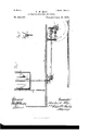
The invention is clearly illustrated in the accompanying drawings, which, with the letters of reference marked thereon, form a part of this specification, and in which-' Figure lis a sectional elevation showing part Aof the indicator-actuating mechanism connected with the ear-axle. Fig.- 2 is a face view of the indicator proper, parts being broken away to disclose the internal arrangement. Fig. 3 is a vertical section taken on the line a: of Fig. 2. Fig. 4 is a vertical section taken on the line y y of Fig. 2. Fig. 5 is a rear end view showing the worm and other portions of the indicator actuating mechanism. Fig. (i is a perspective detail indicating one of the supporting-brackets. Fig. 7 is an edge or rear view of the supporting-yoke, with the shaft shown as supported thereby.
Like letters of reference indicate like parts throughout the several views.
I greatly simplify the construction of the device as patented, reducing the number of gears, provide for the giving of the parts in 1889. Serial No.328,387. (Nomodel.)
going round curves to prevent breaking or twisting of the parts, and provide other novel features, as will hereinafter appear, and be particularly pointed out in the claims.
Referring now to the details of the drawings by letter, A designates the bottom of the car-body; B, the end wall of the same; C, one of the car-axles, and D a wheel thereon. The axle C is provided with a worm C',which is in gear with a worm-wheel E, fixed on the rear end of a shaft E', mounted lengthwise of the car in bearings' F, F', and H'. On the forward end of the shaft E' is fixed by the key G3 a hub bevel-gear E2, which engages with a bevel-gear G on the lower end of a vertical shaft G', journaled at its lower end in a bearing G4, held to the car-bottom A in connection with the hanger F'. The rear bearing F of the shaft E' is formed in a casting F2, loosely embracing the Worm C' on the car-axle C, and held thereon by the strap F3, bolted tothe casting F2. To the casting F2 is bolted a hinge H5, connected to the hanger F4, bolted on the car-bottom A.
On the rod E' is a knuckle-joint I-I directly over the hinge-joint H5, held in a bearing H of the hanger F4, and a collar and set-screw H4 on the shaft E' between the joint H and the bearing F, and thereby allowing the rod E' to oscillate freely in going round curves. The shaft E', leading to the front end of the car through the hub bevel-gear E2, running in bearing of the hanger F', and the hub bevelgear E2, running in a bearing G5, held to hanger F' by a cap G, bolted to said hanger F', and the hanger F' being bolted solid to the car-bottom A, making the rodA E' drive the hub-gear G2 by the key in the slot G3, allows the shaft E' to work or slide freely in the ,hub bevel-gear E2 as the car vibrates up and down in its movements.
'lhe shaft G extends upward into the compartment I of the casing I of the indicator proper, which is suitably supported in a conspicuous position near the top of the car. The upper part of the shaft G is mounted to turn freely in bearings .I and J', secured to the inner skeleton wall I2 of the compartment I', and between the two bearings J and J' are bevel-gears K and K', both mounted on the IOO shaft G', so as to slide freely, but compelled to turn with the said shaft, as by'means of the usual featherand groove.
The gears K and K' are provided with an nularly-grooved bosses K2 and K5, which are engaged by the forked levers K4 and K5, piv'- oted to the wall I2, vand having handles projectlng through the casing I, by which either gear K or K' may be thrown into engagement with the large gear L, or both disengaged therefrom. Suitable stops may be `provided for holding the handles of the levers, in their adjusted positions. .'lhelarge bevel-gear L is iixed on the shaft L', projecting through the wall I2 into the adjacent compartment I5 of the casing and journaled in the wall I2 and the inner skeleton Wall Itof the compartment I5.
On the shaft L', within the compartment I5, 1s f ixed a gear-wheel M, which simultaneously drives in reverse direction of multiple gear M' and M2, arranged, respectively, in the top and bottom of the compartment I2. The gear- Wheels M' and M2 are mounted `loosely on the shafts N and N', which extend through the wall I4 and form the inner journals of the parallel carrier-rollers O and O', arranged in the main ,compartment I5 of the indlcator-casing and having their outer journals mounted to the inner walls Z Z of the compartment I5.
On the rollers 0 and O' is wound a paper or fabric strip, ongwhich are printed or produced 1n succession the names of the stations, streets, dac., in the order in `which they are reached by the car. The strip is guided by the rollers Q and Q', placed on each side of the glazed opening IB in the compartment I5 close to the front side I5 of the casing, so that the various names will appear in succession on the fabric, the names being near and far apart, according to the distance from one street or station to another at the narrow glazed openings I7 and Ia in the front wall.
On the inner rollers, journaled on the shafts N and N', are the clutches R and R', R2 and R4, which are regulated by means of the forked levers R5 and R5, operating in the usual manner to reverse the motion of the fabric, as will be readily understood. The fabric is arranged, as shown in Fig. 4, to show the streets, stations, &c., on the fabric, by which arrangement the names on the strip P, being placed in accordance with the distance traveled between `the places which theyrespectively designate, will appear at the front opening I8 when the car arrives at such places, as the strip travels exactly in accordance with the car.
At the end of the trip, if the car is reversed, the motion ofthe carrier-rollers O and O' can be reversed by the handles of the levers R4 `car is not reversed, but merely drawn backward as 1t was in going forward, no reversal of the actuating mechanismwill be'necessary,
as the relation of the driving-axle is reversed.
A spur-wheel T is lixed on theA shaft L'. just back of the large bevel-gear L, and is en-v gaged with a small spur-wheel Tf, the shaft N5 'of which has a squared end projecting through the wall I of thecasing to receive a common clock-crank key. Thus when the strip P becomes misplaced, as by the slipping of the car-wheels, it may be readily `adj usted by throwing both bevel-gears Kand K' out ers O and O' taut `while the ribbon is wound up by the motion of the traveling car, the said screws and springs serving to cause the ribbon to be Wound tightly and evenly.
. What I claim as new is- 1. The combination, with the car-wheel, its axle, a worm on the axle, the hanger on the Worm, the shaft E', the joint between the same, and the worm which meshes with the worm on the axle, of the casting F2, and the hinge H5, directly beneath the joint' in the shaft E, substantially as described.
2. The combination, with the rod E', the` hanger F4, and the bearing F, supported on the end of said rod by the said hanger, of the collar and clamping-screw and casting F2, the joint H at the end of the shaftV E', and the hinge H5, directly beneath the joint, substantially as and for the purpose specified.
3. The combination, with the car-bottom, of the hanger F', attached thereto, the hanger F', bolted to the bottom of the car at a distance from the hanger F', the axle, the bearing F, formed in -a casting loosely embracing the axle and secured thereto by the strap, as shown, a hinge connecting the casting F4 and bearing F, and the rod E', having a bearing in the casting F4, substantially as shown and de scribed.
4. The combination, with the car-bottom, of the hanger F', attached thereto, the hanger F4, bolted to the bottom of the car, the axle, the bearing F, formed. in a casting loosely embracing the axle and secured thereto by the strap, as shown, a hinge connecting the casting F5 and bearing F, the rod E', having a bearing in the casting F4, and the hinge I-l5 between the casting Ftand the bearing F2, directly beneath the tirst-mentioned hinge, substantially as shown and described.
In testimony that I claim the above I have hereunto subscribed my name in the presence of two witnesses.
CHARLES W. MAY. Witnesses:
FRANK. A. LEWIS, L. E. HUGGINS.`
IOO
ITO
Publications (1)
| Publication Number | Publication Date |
|---|---|
| US425685A true US425685A (en) | 1890-04-15 |
Family
ID=2494598
Family Applications (1)
| Application Number | Title | Priority Date | Filing Date |
|---|---|---|---|
| US425685D Expired - Lifetime US425685A (en) | Automatic station indicator |
Country Status (1)
| Country | Link |
|---|---|
| US (1) | US425685A (en) |
Cited By (1)
| Publication number | Priority date | Publication date | Assignee | Title |
|---|---|---|---|---|
| US20050175039A1 (en) * | 2004-01-29 | 2005-08-11 | Horst Haefner | Radio-controlled clock and method for determining the signal quality of a transmitted time signal |
-
0
- US US425685D patent/US425685A/en not_active Expired - Lifetime
Cited By (1)
| Publication number | Priority date | Publication date | Assignee | Title |
|---|---|---|---|---|
| US20050175039A1 (en) * | 2004-01-29 | 2005-08-11 | Horst Haefner | Radio-controlled clock and method for determining the signal quality of a transmitted time signal |
Similar Documents
| Publication | Publication Date | Title |
|---|---|---|
| US425685A (en) | Automatic station indicator | |
| US374484A (en) | Automatic station indicator | |
| US343760A (en) | William | |
| US591941A (en) | Shimer | |
| US250236A (en) | Station-indicator | |
| US435427A (en) | kelsey | |
| US501477A (en) | chormann | |
| US1155694A (en) | Automatic station-indicator for cars. | |
| US173251A (en) | Improvement in speed-recorders | |
| US525755A (en) | Station-indicator | |
| US674032A (en) | Time-schedule indicator. | |
| US414885A (en) | keasky | |
| US605938A (en) | turner | |
| US334478A (en) | Railway-station indicator | |
| US494189A (en) | Indicator for locomotive-engineers | |
| US1229878A (en) | Headway-recorder. | |
| US774137A (en) | Automatic street or station indicator for street-railway cars, &c. | |
| US709293A (en) | Station-indicator. | |
| US466141A (en) | Indicator for railways | |
| US154963A (en) | Improvement in station-indicators | |
| US251707A (en) | edwards | |
| US1019007A (en) | Distance and speed meter. | |
| US1047079A (en) | Station-indicator. | |
| US153470A (en) | Improvement in speed-recorders for railroad-trains | |
| US796766A (en) | Device for turning electric-car signs. |