US4241730A - Knee support - Google Patents
Knee support Download PDFInfo
- Publication number
- US4241730A US4241730A US05/831,187 US83118777A US4241730A US 4241730 A US4241730 A US 4241730A US 83118777 A US83118777 A US 83118777A US 4241730 A US4241730 A US 4241730A
- Authority
- US
- United States
- Prior art keywords
- knee
- medial
- brace
- support
- joint
- Prior art date
- Legal status (The legal status is an assumption and is not a legal conclusion. Google has not performed a legal analysis and makes no representation as to the accuracy of the status listed.)
- Expired - Lifetime
Links
- 210000003127 knee Anatomy 0.000 title claims abstract description 38
- 230000033001 locomotion Effects 0.000 claims abstract description 13
- 210000003414 extremity Anatomy 0.000 claims abstract description 9
- 210000004417 patella Anatomy 0.000 claims abstract description 9
- 210000000689 upper leg Anatomy 0.000 claims abstract description 9
- 230000002159 abnormal effect Effects 0.000 claims abstract description 8
- 238000006073 displacement reaction Methods 0.000 claims abstract description 6
- 210000000629 knee joint Anatomy 0.000 claims description 9
- 210000002414 leg Anatomy 0.000 claims description 8
- 230000037081 physical activity Effects 0.000 claims 2
- 239000000463 material Substances 0.000 description 3
- 210000002303 tibia Anatomy 0.000 description 3
- 210000000988 bone and bone Anatomy 0.000 description 2
- 230000007246 mechanism Effects 0.000 description 2
- 229920003023 plastic Polymers 0.000 description 2
- 239000004033 plastic Substances 0.000 description 2
- 206010061245 Internal injury Diseases 0.000 description 1
- 206010023204 Joint dislocation Diseases 0.000 description 1
- 230000007321 biological mechanism Effects 0.000 description 1
- 230000015572 biosynthetic process Effects 0.000 description 1
- 230000037396 body weight Effects 0.000 description 1
- 238000010276 construction Methods 0.000 description 1
- 230000006378 damage Effects 0.000 description 1
- 230000001419 dependent effect Effects 0.000 description 1
- -1 for example Substances 0.000 description 1
- 238000005755 formation reaction Methods 0.000 description 1
- 238000002513 implantation Methods 0.000 description 1
- 210000003041 ligament Anatomy 0.000 description 1
- 229910001234 light alloy Inorganic materials 0.000 description 1
- 239000002184 metal Substances 0.000 description 1
- 230000005019 pattern of movement Effects 0.000 description 1
- 230000002265 prevention Effects 0.000 description 1
- 238000005096 rolling process Methods 0.000 description 1
- 239000010935 stainless steel Substances 0.000 description 1
- 229910001220 stainless steel Inorganic materials 0.000 description 1
- 238000001356 surgical procedure Methods 0.000 description 1
Images


Classifications
-
- A—HUMAN NECESSITIES
- A61—MEDICAL OR VETERINARY SCIENCE; HYGIENE
- A61F—FILTERS IMPLANTABLE INTO BLOOD VESSELS; PROSTHESES; DEVICES PROVIDING PATENCY TO, OR PREVENTING COLLAPSING OF, TUBULAR STRUCTURES OF THE BODY, e.g. STENTS; ORTHOPAEDIC, NURSING OR CONTRACEPTIVE DEVICES; FOMENTATION; TREATMENT OR PROTECTION OF EYES OR EARS; BANDAGES, DRESSINGS OR ABSORBENT PADS; FIRST-AID KITS
- A61F5/00—Orthopaedic methods or devices for non-surgical treatment of bones or joints; Nursing devices ; Anti-rape devices
- A61F5/01—Orthopaedic devices, e.g. long-term immobilising or pressure directing devices for treating broken or deformed bones such as splints, casts or braces
- A61F5/0102—Orthopaedic devices, e.g. long-term immobilising or pressure directing devices for treating broken or deformed bones such as splints, casts or braces specially adapted for correcting deformities of the limbs or for supporting them; Ortheses, e.g. with articulations
- A61F5/0123—Orthopaedic devices, e.g. long-term immobilising or pressure directing devices for treating broken or deformed bones such as splints, casts or braces specially adapted for correcting deformities of the limbs or for supporting them; Ortheses, e.g. with articulations for the knees
Definitions
- This invention relates to knee supports for the natural human knee and aims at providing a construction which will resist excessive or abnormal torsional strain on the knee joints such as can occur, for example, when a person stumbles or endeavours to turn too sharply, especially if the whole or the greater part of the body weight is being supported at that instant on one leg.
- Tibial rotation thus occurs over the range of flexion and extension of the knee which takes place during normal walking and running, and any impediment thereto, or excess torque, due to external forces--such as regularly arise in the course of sports and games by the need for quick and vigorous stopping, starting and turning--can cause internal injury to and derangement of the knee, especially meniscal tearing. A sudden blow or excess force sideways on the knee can also cause tearing of the ligaments.
- the present invention therefore aims at providing an approximation to the rigorous but unattainable solution of internal knee derangement as a result of violent or excessive torsional or sideways strain--particularly (but not exclusively) for athletes--by means of an externally applied device which conforms to the normal biological mechanism of the knee joint but resists any abnormal pattern of movement imposed by external force, thereby tending to reduce the risk of damage to the internal structure of the joint.
- a knee support for opposing excessive or abnormal strain on the joint, comprising a pair of pivotally interconnected rigid braces, the one adapted to embrace snugly the front of the thigh just above the patella and the other adapted to embrace snugly the front of the shin just below the patella, the pivots being aligned approximately on the mean medial-lateral axis of flexion of the knee and at least the pivot on the lateral side having freedom of universal pivotal motion whilst that on the medial side has limited freedom of relative bodily displacement in the anterior-posterior direction, both freedoms being of sufficient magnitude to accommodate the wearer's normal degree of tibial rotation during flexion and extension, and means for locating each brace firmly on its respective component of the limb.
- the lateral pivot is of the ball-and-socket type
- the medial pivot may be of a pin-and-slot or a rack-and-pinion type.
- each brace is firmly located on its respective component of the limb by a strap or like binding passing completely round the limb component.
- the dimension of the braces, and the extent of the free travel of the medial pivot may need to be tailored to the physical proportions of the wearer's limb. It may also be desirable to make provision for a certain degree of universal motion in the medial pivot as well as that provided in the lateral pivot.
- the extent of free motion in the medial pivot is mainly dependent on the degree of normal tibial rotation of the wearer's knee, and provision may be required for adjustment of this, for example by means of an adjustable stop at one end of the slot.
- the medial pivot as a rack-and-pinion type articulation so as to dictate the relative displacement of the braces about the universal-motion lateral pivot.
- a convenient equivalent to a rack and pinion is a taut inelastic cord anchored at its free ends to the ends of the slot and wrapped round the pin in non-slip manner.
- FIG. 1 is an elevation, seen from the lateral side, of a first embodiment of knee support, comprising a pair of pivotally interconnected braces for a right knee in their relative positions at full extension:
- FIG. 2 is an elevation, seen from the medial side, of the braces in position on the right knee when in full extension:
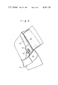
- FIG. 3 is a view similar to FIG. 2 showing the knee flexed to approximately 90°;
- FIG. 4 is a view similar to FIG. 3 but seen from the lateral side
- FIG. 5 is an anterior elevation of FIG. 2
- FIG. 6 is a front elevation of a second embodiment of the invention.
- FIG. 7 is a side elevation of the embodiment of FIG. 6,
- FIG. 8 is an elevation, seen from the lateral side, of a third embodiment of knee support.
- FIG. 9 is a similar view of a fourth embodiment.
- the knee support illustrated in FIGS. 1 to 5 consists basically of two generally C-shaped rigid braces 10, 12. These are preferably of a high grade light alloy which may be coated with a plastics layer, at least on its internal surface, to improve wearer comfort. On the lateral side each brace is bent at right-angles into a straight extension 10a, 12a respectively which is adapted to lie close to the wearer's leg. The free ends of these straight lateral extensions are articulated together by a ball-and-socket joint 14 which has freedom of normal pivotal motion for at least 120° and freedom of universal motion over a cone angle of several degrees to the common plane containing the extensions 10a, 12a.
- the other, curved, ends of the braces 10, 12 are articulated together by a pin-and-slot connection 16, 18.
- the pin 16 preferably has a limited freedom of universal motion--mainly to avoid jamming because of the mutual changes of plane of the two ends of the braces during flexion and extension of the knee.
- the pin 16 itself, however, is a relatively close fit diametrically within the slot 18.
- braces 10, 12 The manner of securing the braces 10, 12 to the wearer's leg is shown as a strong webbing strap or binding 20, 22 respectively. It may also be desirable to shape each brace 10, 12 so as to fit closely the contour of the relative bones where they approach nearest the surface of the skin.
- the material of the binding 20, 22 may also be locally reinforced or substituted by a piece of specially contoured non-deformable material which fits snugly over or into a portion of the thigh or shin component--for example, a pad which fits snugly into the thigh cavity behind the knee.
- Such localised formations reduce the risk that either brace, 10, 12 will tend to rotate with the flesh relative to the respective bone and thus become less effective as a restraint on excessive or abnormal torque at the condylar surfaces of the knee joint.
- each brace 10, 12 is optional but lightness and rigidity are the principal requirements, coupled with a comfortable inward surface which makes contact with the wearer's flesh.
- the exact structure of the ball and socket joint 14 and of the pin and slot articulation 16, 18 is optional provided that both articulations acting in concert permit a tibial rotation of approximately 15°.
- the braces 10, 12 may sometimes require to be "tailored" to a particular wearer's leg, but it is envisaged that a given size and contour of the brace will suitably fit a significant number of wearers even though they may differ considerably in height, weight and physique. Obviously, however, the optimum results in the task of opposing excessive torque on the knee joint are to be expected from a support whose braces 10, 12 and preferably also their respective anchorages 20, 22 are tailored to the contours and structure of each particular wearer.
- FIGS. 6 and 7 is similar in operation to that illustrated in FIGS. 1 to 5, and differs in that joint 14 and the pin and slot connection 16, 18 are formed in respective pairs of joint members which are secured to the rest of the brace rather than being integral with it. All of the brace apart from the joint members can be made of a plastics material, and the joint members may be of metal, for example, stainless steel.
Landscapes
- Health & Medical Sciences (AREA)
- Nursing (AREA)
- Orthopedic Medicine & Surgery (AREA)
- Engineering & Computer Science (AREA)
- Biomedical Technology (AREA)
- Heart & Thoracic Surgery (AREA)
- Vascular Medicine (AREA)
- Life Sciences & Earth Sciences (AREA)
- Animal Behavior & Ethology (AREA)
- General Health & Medical Sciences (AREA)
- Public Health (AREA)
- Veterinary Medicine (AREA)
- Prostheses (AREA)
- Orthopedics, Nursing, And Contraception (AREA)
Abstract
A knee support is provided for opposing excessive or abnormal strain or torque on the joint. The support has a pair of pivotally interconnected rigid braces one of which snugly embraces the front of the thigh just above the patella and the other of which snugly embraces the front of the shin just below the patella. The pivots are aligned approximately on the mean medial-lateral axis of flexion of the knee and at least the pivot on the lateral side has freedom of universal pivotal motion while that on the medial side has limited freedom of relative bodily displacement in the anterior-posterior direction. Both freedoms are of sufficient magnitude to accommodate the wearer's normal degree of tibial rotation during flexion and extension. Means are provided for locating each brace firmly on its respective component of the limb.
Description
This invention relates to knee supports for the natural human knee and aims at providing a construction which will resist excessive or abnormal torsional strain on the knee joints such as can occur, for example, when a person stumbles or endeavours to turn too sharply, especially if the whole or the greater part of the body weight is being supported at that instant on one leg.
During normal flexion and extension of a healthy knee, various relative motions occur between the femur and the tibia. The most obvious of these is the large "hinge" motion which normally extends to about 120°. Superimposed on the hinge motion, however, are other and smaller relative motions one of which is termed variously "tibial rotation" and "screw-home". The tibia rotates about its axis relative to the femur by an average of 13°-15°, causing an outward deflection of the foot during extension and inward deflection during flexion. Tibial rotation thus occurs over the range of flexion and extension of the knee which takes place during normal walking and running, and any impediment thereto, or excess torque, due to external forces--such as regularly arise in the course of sports and games by the need for quick and vigorous stopping, starting and turning--can cause internal injury to and derangement of the knee, especially meniscal tearing. A sudden blow or excess force sideways on the knee can also cause tearing of the ligaments.
Ideally, prevention of internal derangement of the knee resulting from any of the above-mentioned external forces would involve some synchronously acting mechanism directly linking the femur and the tibia, but as this would involve the opening of the knee joint by surgery and the implantation of some mechanical device, it represents, for practical purposes, an unrealistic and ideal solution of the problem of knee strain. The present invention therefore aims at providing an approximation to the rigorous but unattainable solution of internal knee derangement as a result of violent or excessive torsional or sideways strain--particularly (but not exclusively) for athletes--by means of an externally applied device which conforms to the normal biological mechanism of the knee joint but resists any abnormal pattern of movement imposed by external force, thereby tending to reduce the risk of damage to the internal structure of the joint.
According to the present invention there is provided a knee support for opposing excessive or abnormal strain on the joint, comprising a pair of pivotally interconnected rigid braces, the one adapted to embrace snugly the front of the thigh just above the patella and the other adapted to embrace snugly the front of the shin just below the patella, the pivots being aligned approximately on the mean medial-lateral axis of flexion of the knee and at least the pivot on the lateral side having freedom of universal pivotal motion whilst that on the medial side has limited freedom of relative bodily displacement in the anterior-posterior direction, both freedoms being of sufficient magnitude to accommodate the wearer's normal degree of tibial rotation during flexion and extension, and means for locating each brace firmly on its respective component of the limb.
Preferably, the lateral pivot is of the ball-and-socket type, and the medial pivot may be of a pin-and-slot or a rack-and-pinion type.
Conveniently, each brace is firmly located on its respective component of the limb by a strap or like binding passing completely round the limb component.
The dimension of the braces, and the extent of the free travel of the medial pivot may need to be tailored to the physical proportions of the wearer's limb. It may also be desirable to make provision for a certain degree of universal motion in the medial pivot as well as that provided in the lateral pivot. The extent of free motion in the medial pivot is mainly dependent on the degree of normal tibial rotation of the wearer's knee, and provision may be required for adjustment of this, for example by means of an adjustable stop at one end of the slot. Furthermore, since it is essential that the support as a whole should impose no restraint on the natural tibial rotation of the knee but maximum restraint on both excessive or insufficient rotation due to external forces, it may be advantageous to form the medial pivot as a rack-and-pinion type articulation so as to dictate the relative displacement of the braces about the universal-motion lateral pivot. A convenient equivalent to a rack and pinion is a taut inelastic cord anchored at its free ends to the ends of the slot and wrapped round the pin in non-slip manner.
Two practical embodiments of the present invention will now be described, by way of illustration only, with reference to the accompanying drawings in which:
FIG. 1 is an elevation, seen from the lateral side, of a first embodiment of knee support, comprising a pair of pivotally interconnected braces for a right knee in their relative positions at full extension:
FIG. 2 is an elevation, seen from the medial side, of the braces in position on the right knee when in full extension:
FIG. 3 is a view similar to FIG. 2 showing the knee flexed to approximately 90°;
FIG. 4 is a view similar to FIG. 3 but seen from the lateral side,
FIG. 5 is an anterior elevation of FIG. 2,
FIG. 6 is a front elevation of a second embodiment of the invention,
FIG. 7 is a side elevation of the embodiment of FIG. 6,
FIG. 8 is an elevation, seen from the lateral side, of a third embodiment of knee support, and
FIG. 9 is a similar view of a fourth embodiment.
The knee support illustrated in FIGS. 1 to 5 consists basically of two generally C-shaped rigid braces 10, 12. These are preferably of a high grade light alloy which may be coated with a plastics layer, at least on its internal surface, to improve wearer comfort. On the lateral side each brace is bent at right-angles into a straight extension 10a, 12a respectively which is adapted to lie close to the wearer's leg. The free ends of these straight lateral extensions are articulated together by a ball-and-socket joint 14 which has freedom of normal pivotal motion for at least 120° and freedom of universal motion over a cone angle of several degrees to the common plane containing the extensions 10a, 12a.
The other, curved, ends of the braces 10, 12 are articulated together by a pin-and- slot connection 16, 18. In this articulation also the pin 16, preferably has a limited freedom of universal motion--mainly to avoid jamming because of the mutual changes of plane of the two ends of the braces during flexion and extension of the knee. The pin 16 itself, however, is a relatively close fit diametrically within the slot 18.
As has already been suggested in British Pat. No. 1,377,561, which related to knee joints for artificial limbs, it may be found desirable to form the pin and slot articulation 16, 18 in the manner of a rack and pinion, as shown in FIG. 8. The pinion 116 is displaced along the toothed slot or rack 118 synchronously, with the tibial rotation taking place naturally in the knee joint. A further alternative is shown in FIG. 9, where an inelastic cord 125 may be wrapped around, and anchored to, the pin 216 and have its ends 127, 128 anchored to the ends of the slot 218. This is a relatively frictionless non-slip drive mechanism which ensures rolling of the pin 216 without slipping on the appropriate longitudinal wall of the slot 218.
The manner of securing the braces 10, 12 to the wearer's leg is shown as a strong webbing strap or binding 20, 22 respectively. It may also be desirable to shape each brace 10, 12 so as to fit closely the contour of the relative bones where they approach nearest the surface of the skin. The material of the binding 20, 22 may also be locally reinforced or substituted by a piece of specially contoured non-deformable material which fits snugly over or into a portion of the thigh or shin component--for example, a pad which fits snugly into the thigh cavity behind the knee. Such localised formations reduce the risk that either brace, 10, 12 will tend to rotate with the flesh relative to the respective bone and thus become less effective as a restraint on excessive or abnormal torque at the condylar surfaces of the knee joint.
The structure of each brace 10, 12 is optional but lightness and rigidity are the principal requirements, coupled with a comfortable inward surface which makes contact with the wearer's flesh. Similarly, the exact structure of the ball and socket joint 14 and of the pin and slot articulation 16, 18 is optional provided that both articulations acting in concert permit a tibial rotation of approximately 15°.
The braces 10, 12 may sometimes require to be "tailored" to a particular wearer's leg, but it is envisaged that a given size and contour of the brace will suitably fit a significant number of wearers even though they may differ considerably in height, weight and physique. Obviously, however, the optimum results in the task of opposing excessive torque on the knee joint are to be expected from a support whose braces 10, 12 and preferably also their respective anchorages 20, 22 are tailored to the contours and structure of each particular wearer.
The embodiment illustrated in FIGS. 6 and 7 is similar in operation to that illustrated in FIGS. 1 to 5, and differs in that joint 14 and the pin and slot connection 16, 18 are formed in respective pairs of joint members which are secured to the rest of the brace rather than being integral with it. All of the brace apart from the joint members can be made of a plastics material, and the joint members may be of metal, for example, stainless steel.
Claims (13)
1. A knee support for opposing excessive or abnormal strain on the joint, comprising a pair of pivotally interconnected rigid braces, the one adapted to embrace snugly the front of the thigh just above the patella and the other adapted to embrace snugly the front of the shin just below the patella, the pivots being aligned approximately on the mean medial-lateral axis of flexion of the knee and at least the pivot on the lateral side having freedom of universal pivotal motion whilst that on the medial side has limited freedom of relative bodily displacement in the anterior-posterior direction, both freedoms being of sufficient magnitude to accommodate the wearer's normal degree of tibial rotation during flexion and extension, and means for locating each brace firmly on its respective component of the limb.
2. A knee support as claimed in claim 1, wherein the lateral pivot is provided by a ball and socket joint.
3. A knee support as claimed in claim 1, wherein the medial pivot is provided by a pin slidably engaging in a slot.
4. A knee support as claimed in claim 3, wherein a taut, inelastic string is secured by its ends to opposite ends of the slot and is wrapped around the anchored to the pin.
5. A knee support as claimed in claim 1, wherein the medial pivot is provided by a rack and pinion joint.
6. A knee support as claimed in claim 1, wherein each brace has a respective joint member secured to each end thereof, the joint members providing the lateral and medial pivots.
7. A knee support for protection of the knee by opposing excessive or abnormal strain on the knee joint during physical activity, the support comprising a pair of rigid braces, the first brace being adapted to embrace snugly the front of the thigh just above the patella and the second brace being adapted to embrace snugly the front of the shin just below the patella, each brace extending approximately from the medial side to the lateral side of the leg portion being embraced; a lateral side pivot means connecting the two braces and adapted to be located approximately on the lateral side of the mean medial-lateral axis of flexion of the knee, the lateral side pivot having freedom of universal pivotal motion; and medial side pivot means connecting the two braces on the medial side and and adapted to be located approximately on the mean medial-lateral axis of flexion of the knee, the medial side pivot having limited freedom of relative bodily displacement in the anterior-posterior direction, both freedoms being of sufficient magnitude to accommodate the wearer's normal degree of tibial rotation during flexion and extension; and securing means for locating and securing each brace firmly on its respective limb component.
8. The knee support of claim 7 wherein the combined action of the medial and lateral joints permit a tibial rotation by the wearer of approximately 15°.
9. An articulated knee support for protection of the knee, by opposing excessive or abnormal strain on the knee joint during physical activity, the support comprising a first brace and a second brace, each brace being generally C-shaped and rigid and adapted to fit against and extend across the front of the leg of the wearer, above and below the patella, respectively; a straight extension, extending at right angles from the lateral end of each brace toward the other brace, adapted to extend adjacent the lateral side of a wearer's leg; a ball-and-socket type universal joint connecting the straight extensions; a second pivoting joint connecting the medial portions of the braces and having the capability of limited relative bodily displacement in the anterior-posterior direction; the two joints being adapted to be located approximately on the medial lateral axis of flexion of the knee, when the two braces are properly fitted against the leg of the wearer; the two pivots being adapted to accommodate the wearer's normal degree of tibial rotation during flexion and extension, and strap means for firmly securing each brace to the proper location on the limb of the wearer.
10. The support of claim 9 wherein the medial pivot comprises a pin-in-slot joint.
11. The support of claim 10 wherein the pin has the capacity of a limited freedom of universal motion.
12. The support of claim 10 wherein the pin and slot pivot joint is formed as a rack and pinion.
13. The support of claim 10 wherein the medial and lateral joints acting in concert permit a tibial rotation of approximately 15°.
Applications Claiming Priority (2)
| Application Number | Priority Date | Filing Date | Title |
|---|---|---|---|
| GB38813/76A GB1534434A (en) | 1976-09-20 | 1976-09-20 | Knee support |
| GB38813/76 | 1976-09-20 |
Publications (1)
| Publication Number | Publication Date |
|---|---|
| US4241730A true US4241730A (en) | 1980-12-30 |
Family
ID=10405846
Family Applications (1)
| Application Number | Title | Priority Date | Filing Date |
|---|---|---|---|
| US05/831,187 Expired - Lifetime US4241730A (en) | 1976-09-20 | 1977-09-07 | Knee support |
Country Status (6)
| Country | Link |
|---|---|
| US (1) | US4241730A (en) |
| AU (1) | AU509503B2 (en) |
| CA (1) | CA1091114A (en) |
| GB (1) | GB1534434A (en) |
| NZ (1) | NZ185209A (en) |
| ZA (1) | ZA775289B (en) |
Cited By (40)
| Publication number | Priority date | Publication date | Assignee | Title |
|---|---|---|---|---|
| US4361142A (en) * | 1981-08-20 | 1982-11-30 | Northwestern University | Knee orthosis and joint construction therefor |
| US4407276A (en) * | 1981-01-22 | 1983-10-04 | Medical Designs, Inc. | Brace for articulated limbs |
| US4635623A (en) * | 1983-10-24 | 1987-01-13 | J. E. Hanger Limited | Brace for an articulating limb |
| US4637382A (en) * | 1982-04-27 | 1987-01-20 | Brigham & Women's Hospital | Motion-guiding load-bearing external linkage for the knee |
| US4655201A (en) * | 1984-07-13 | 1987-04-07 | Northwestern University | Knee orthosis and joint construction therefor |
| US4856501A (en) * | 1987-06-29 | 1989-08-15 | Innovation Sports, Inc. | Knee brace having adjustable width frame pivoted to cuffs |
| US4886054A (en) * | 1987-06-29 | 1989-12-12 | Innovation Sports, Inc. | Knee brace with cammed stop lever |
| US5131385A (en) * | 1987-11-13 | 1992-07-21 | Bauerfeind Gmbh & Co. | Orthesis for the human knee |
| US5302169A (en) * | 1993-01-04 | 1994-04-12 | Generation Ii Orthotics Inc. | Post operative knee brace |
| US5741221A (en) * | 1994-10-07 | 1998-04-21 | Wetz; Hans Henning | Knee-joint orthesis having different medical and lateral hinge mechanisms |
| US5800370A (en) * | 1993-03-24 | 1998-09-01 | Joachim Theusner | Exoprosthesis for the human knee joint |
| US5873848A (en) * | 1996-06-14 | 1999-02-23 | Depuy, Inc. | Orthopedic brace |
| US6110137A (en) * | 1995-01-03 | 2000-08-29 | Dj Orthopedics, Llc | Orthopaedic brace having one-piece cuff |
| USD433756S (en) * | 1999-11-02 | 2000-11-14 | Castillo Edward L | Osteoarthritis knee brace |
| US20020107465A1 (en) * | 2001-01-29 | 2002-08-08 | Brad Freeman | Joint brace with rapid-release securement members |
| US6461318B2 (en) | 2001-01-29 | 2002-10-08 | Brad Freeman | Anatomical brace with rapid-release securement members |
| US6464657B1 (en) | 2000-05-24 | 2002-10-15 | James D. Castillo | Anatomical joint brace field of the invention |
| US20020183674A1 (en) * | 2000-01-18 | 2002-12-05 | Castillo Edward L. | Osteo-arthritis knee brace |
| US6623439B2 (en) | 2001-08-31 | 2003-09-23 | Dj Orthopedics, Llc | Contoured knee brace frame |
| US6689080B2 (en) | 2000-05-24 | 2004-02-10 | Asterisk.Asterisk Llc | Joint brace with limb-conforming arcuately adjustable cuffs |
| US6796951B2 (en) | 2001-02-02 | 2004-09-28 | Asterisk.Asterisk. Llc | Anatomical joint brace with adjustable joint extension limiter |
| US20050148916A1 (en) * | 2004-01-07 | 2005-07-07 | Nathanson Jeremy J. | Knee brace hinges with adaptive motion |
| US20050148915A1 (en) * | 2004-01-07 | 2005-07-07 | Nathanson Jeremy J. | Knee brace hinges having dual axes of rotation |
| US20050187505A1 (en) * | 2004-02-24 | 2005-08-25 | Tamarack Habilitation Technologies, Inc. | Spherical joint orthosis |
| US6962571B2 (en) | 2001-02-02 | 2005-11-08 | Asterisk.Asterisk, Llc | Joint brace with multi-planar pivoting assembly and infinitely adjustable limb extension regulator |
| US7001349B2 (en) | 2003-08-12 | 2006-02-21 | Otto Bock Healthcare Gmbh | Orthopedic splint |
| US7044925B2 (en) | 2002-12-30 | 2006-05-16 | Innovation Sports, Llc | Hinge system for regulating knee joint flexion and extension |
| US20080195014A1 (en) * | 2007-02-12 | 2008-08-14 | Arni Thor Ingimundarson | Orthopedic component for use with an orthopedic brace |
| US20110071452A1 (en) * | 2008-05-20 | 2011-03-24 | Otto Bock Healthcare Gmbh | Knee orthosis, and method for controlling a knee orthosis |
| USD665505S1 (en) | 2010-08-20 | 2012-08-14 | Ossur Hf | Orthopedic device |
| US8419670B2 (en) | 2011-02-24 | 2013-04-16 | Breg, Inc. | Frame for an orthopedic brace having a truss structure and an associated strapping system |
| US8740829B2 (en) | 2010-08-20 | 2014-06-03 | Ossur Hf | Configurable subshell components in orthopedic devices |
| US8882689B2 (en) | 2010-12-20 | 2014-11-11 | Asterisk.Asterisk, Llc | Knee brace |
| JP2017522982A (en) * | 2014-08-05 | 2017-08-17 | ユナイテッド サージカル アソシエイツ,インコーポレイテッドUnited Surgical Associates, Inc. | Knee orthosis with adjustable strut length and dynamic strut extension |
| US10420668B2 (en) | 2014-11-20 | 2019-09-24 | Ossur Iceland Ehf | Patella cup |
| US20190321210A1 (en) * | 2017-12-07 | 2019-10-24 | 2330-2029 Québec Inc | Knee orthosis with helicoidal axis and method of design and fabrication thereof |
| US10588770B2 (en) | 2014-07-10 | 2020-03-17 | Ossur Hf | Versatile orthopedic device |
| US11547774B2 (en) | 2018-06-11 | 2023-01-10 | Ossur Iceland Ehf | Multi-component frame for use in an orthopedic device |
| US11857450B2 (en) | 2020-03-06 | 2024-01-02 | Ossur Iceland Ehf | Strap attachment and orthopedic device using the same |
| US12178729B2 (en) | 2019-03-26 | 2024-12-31 | Ossur Iceland Ehf | Hinge assembly for an orthopedic device |
Families Citing this family (10)
| Publication number | Priority date | Publication date | Assignee | Title |
|---|---|---|---|---|
| US4256097A (en) * | 1978-12-29 | 1981-03-17 | Willis Robert E | Orthopedic apparatus for protecting and supporting a bone joint |
| FR2454295A1 (en) * | 1979-04-19 | 1980-11-14 | Rambert Andre | Two-part articulated knee splint - has hinge pin passing through link via elongated hole in line with opposite pin |
| FR2472375A2 (en) * | 1979-12-26 | 1981-07-03 | Rambert Andre | Articulated knee-joint splint - has link between uprights limiting relative angular movement |
| US4393542A (en) * | 1980-07-21 | 1983-07-19 | Gonzalo Martinez | Polycentric hinge for cast-braces |
| FR2552660B1 (en) * | 1983-09-29 | 1988-10-14 | Delbos Jean | KNEE JOINT ASSISTANCE APPARATUS |
| FR2600528A1 (en) * | 1986-06-24 | 1987-12-31 | Icp Sa | Progressive knee splint |
| US4821707A (en) * | 1987-12-28 | 1989-04-18 | Andre Audette | Mechanical articulated joint for knee braces |
| FR2640873A1 (en) * | 1988-12-27 | 1990-06-29 | Thompson Gordon | Walking aid device |
| DE19605734C2 (en) * | 1996-02-16 | 2000-01-20 | Beiersdorf Ag | Knee joint orthosis with different lateral and medial orthotic joint |
| DE10219662A1 (en) * | 2002-05-02 | 2003-11-13 | Gottinger Orthopaedie Technik | Flexible joint for orthesis supporting injured knee has upper lever with sliding and swiveling pivot moving in slot in top of lower lever and with angled extension moving on pivoted link |
Citations (8)
| Publication number | Priority date | Publication date | Assignee | Title |
|---|---|---|---|---|
| US2654365A (en) * | 1949-11-14 | 1953-10-06 | Archie L Whitaker | Combined body and leg brace |
| US2877033A (en) * | 1956-03-16 | 1959-03-10 | Dreher Mfg Company | Artificial joint |
| US2883982A (en) * | 1956-09-06 | 1959-04-28 | Fred E Rainey | Leg brace |
| US3669105A (en) * | 1969-10-28 | 1972-06-13 | Ignatius F Castiglia | Brace for articulated limbs |
| US3779654A (en) * | 1971-08-06 | 1973-12-18 | R Horne | Artificial joint |
| US3801990A (en) * | 1972-02-16 | 1974-04-09 | A Helfet | Artificial limb with a joint that simulates a bicondylar joint movement |
| US3817244A (en) * | 1972-03-03 | 1974-06-18 | Kendall & Co | Knee brace |
| US3902482A (en) * | 1974-05-21 | 1975-09-02 | George A Taylor | Mechanical joint for an orthopedic brace or prosthesis |
-
1976
- 1976-09-20 GB GB38813/76A patent/GB1534434A/en not_active Expired
-
1977
- 1977-08-31 ZA ZA00775289A patent/ZA775289B/en unknown
- 1977-09-07 US US05/831,187 patent/US4241730A/en not_active Expired - Lifetime
- 1977-09-12 CA CA286,556A patent/CA1091114A/en not_active Expired
- 1977-09-19 NZ NZ185209A patent/NZ185209A/en unknown
- 1977-09-20 AU AU28950/77A patent/AU509503B2/en not_active Expired
Patent Citations (8)
| Publication number | Priority date | Publication date | Assignee | Title |
|---|---|---|---|---|
| US2654365A (en) * | 1949-11-14 | 1953-10-06 | Archie L Whitaker | Combined body and leg brace |
| US2877033A (en) * | 1956-03-16 | 1959-03-10 | Dreher Mfg Company | Artificial joint |
| US2883982A (en) * | 1956-09-06 | 1959-04-28 | Fred E Rainey | Leg brace |
| US3669105A (en) * | 1969-10-28 | 1972-06-13 | Ignatius F Castiglia | Brace for articulated limbs |
| US3779654A (en) * | 1971-08-06 | 1973-12-18 | R Horne | Artificial joint |
| US3801990A (en) * | 1972-02-16 | 1974-04-09 | A Helfet | Artificial limb with a joint that simulates a bicondylar joint movement |
| US3817244A (en) * | 1972-03-03 | 1974-06-18 | Kendall & Co | Knee brace |
| US3902482A (en) * | 1974-05-21 | 1975-09-02 | George A Taylor | Mechanical joint for an orthopedic brace or prosthesis |
Cited By (59)
| Publication number | Priority date | Publication date | Assignee | Title |
|---|---|---|---|---|
| US4407276A (en) * | 1981-01-22 | 1983-10-04 | Medical Designs, Inc. | Brace for articulated limbs |
| US4361142A (en) * | 1981-08-20 | 1982-11-30 | Northwestern University | Knee orthosis and joint construction therefor |
| US4637382A (en) * | 1982-04-27 | 1987-01-20 | Brigham & Women's Hospital | Motion-guiding load-bearing external linkage for the knee |
| US4635623A (en) * | 1983-10-24 | 1987-01-13 | J. E. Hanger Limited | Brace for an articulating limb |
| US4655201A (en) * | 1984-07-13 | 1987-04-07 | Northwestern University | Knee orthosis and joint construction therefor |
| US4886054A (en) * | 1987-06-29 | 1989-12-12 | Innovation Sports, Inc. | Knee brace with cammed stop lever |
| US4856501A (en) * | 1987-06-29 | 1989-08-15 | Innovation Sports, Inc. | Knee brace having adjustable width frame pivoted to cuffs |
| US5131385A (en) * | 1987-11-13 | 1992-07-21 | Bauerfeind Gmbh & Co. | Orthesis for the human knee |
| US5302169A (en) * | 1993-01-04 | 1994-04-12 | Generation Ii Orthotics Inc. | Post operative knee brace |
| US5400806A (en) * | 1993-01-04 | 1995-03-28 | Generation Ii Orthotics, Inc. | Post operative knee brace and method for its use |
| US5800370A (en) * | 1993-03-24 | 1998-09-01 | Joachim Theusner | Exoprosthesis for the human knee joint |
| US5741221A (en) * | 1994-10-07 | 1998-04-21 | Wetz; Hans Henning | Knee-joint orthesis having different medical and lateral hinge mechanisms |
| US6110137A (en) * | 1995-01-03 | 2000-08-29 | Dj Orthopedics, Llc | Orthopaedic brace having one-piece cuff |
| US5873848A (en) * | 1996-06-14 | 1999-02-23 | Depuy, Inc. | Orthopedic brace |
| USD433756S (en) * | 1999-11-02 | 2000-11-14 | Castillo Edward L | Osteoarthritis knee brace |
| US6875187B2 (en) | 2000-01-18 | 2005-04-05 | Innovation Sports, Inc. | Osteo-arthritis knee brace |
| US20020183674A1 (en) * | 2000-01-18 | 2002-12-05 | Castillo Edward L. | Osteo-arthritis knee brace |
| US6464657B1 (en) | 2000-05-24 | 2002-10-15 | James D. Castillo | Anatomical joint brace field of the invention |
| US6689080B2 (en) | 2000-05-24 | 2004-02-10 | Asterisk.Asterisk Llc | Joint brace with limb-conforming arcuately adjustable cuffs |
| US6461318B2 (en) | 2001-01-29 | 2002-10-08 | Brad Freeman | Anatomical brace with rapid-release securement members |
| US6793641B2 (en) | 2001-01-29 | 2004-09-21 | Asterisk.Asterisk, Llc | Joint brace with rapid-release securement members |
| US20020107465A1 (en) * | 2001-01-29 | 2002-08-08 | Brad Freeman | Joint brace with rapid-release securement members |
| US6796951B2 (en) | 2001-02-02 | 2004-09-28 | Asterisk.Asterisk. Llc | Anatomical joint brace with adjustable joint extension limiter |
| US6962571B2 (en) | 2001-02-02 | 2005-11-08 | Asterisk.Asterisk, Llc | Joint brace with multi-planar pivoting assembly and infinitely adjustable limb extension regulator |
| US6623439B2 (en) | 2001-08-31 | 2003-09-23 | Dj Orthopedics, Llc | Contoured knee brace frame |
| US6878126B2 (en) | 2001-08-31 | 2005-04-12 | Dj Orthopedics, Llc | Contoured knee brace frame |
| US7044925B2 (en) | 2002-12-30 | 2006-05-16 | Innovation Sports, Llc | Hinge system for regulating knee joint flexion and extension |
| US7001349B2 (en) | 2003-08-12 | 2006-02-21 | Otto Bock Healthcare Gmbh | Orthopedic splint |
| US8043243B2 (en) | 2004-01-07 | 2011-10-25 | Djo, Llc | Knee brace hinges having dual axes of rotation |
| US20050148915A1 (en) * | 2004-01-07 | 2005-07-07 | Nathanson Jeremy J. | Knee brace hinges having dual axes of rotation |
| US20050148916A1 (en) * | 2004-01-07 | 2005-07-07 | Nathanson Jeremy J. | Knee brace hinges with adaptive motion |
| US7615025B2 (en) | 2004-01-07 | 2009-11-10 | Djo, Llc | Knee brace hinges with adaptive motion |
| US7044926B2 (en) | 2004-02-24 | 2006-05-16 | Tamarack Habilitation Technologies, Inc. | Spherical joint orthosis |
| US20050187505A1 (en) * | 2004-02-24 | 2005-08-25 | Tamarack Habilitation Technologies, Inc. | Spherical joint orthosis |
| US20080195014A1 (en) * | 2007-02-12 | 2008-08-14 | Arni Thor Ingimundarson | Orthopedic component for use with an orthopedic brace |
| US7749183B2 (en) | 2007-02-12 | 2010-07-06 | Ossur Hf | Orthopedic brace including a protector assembly |
| US8048013B2 (en) | 2007-02-12 | 2011-11-01 | Ossur Hf | Orthopedic brace and component for use therewith |
| US8348876B2 (en) | 2007-02-12 | 2013-01-08 | Ossur Hf | Strap retainer |
| US9039644B2 (en) | 2007-02-12 | 2015-05-26 | Ossur Hf | Orthopedic component for use with an orthopedic brace |
| US20110071452A1 (en) * | 2008-05-20 | 2011-03-24 | Otto Bock Healthcare Gmbh | Knee orthosis, and method for controlling a knee orthosis |
| US9022965B2 (en) * | 2008-05-20 | 2015-05-05 | Otto Bock Healthcare Gmbh | Knee orthosis, and method for controlling a knee orthosis |
| USD665505S1 (en) | 2010-08-20 | 2012-08-14 | Ossur Hf | Orthopedic device |
| US10772387B2 (en) | 2010-08-20 | 2020-09-15 | Ossur Hf | Configurable subshell components in orthopedic devices |
| US8740829B2 (en) | 2010-08-20 | 2014-06-03 | Ossur Hf | Configurable subshell components in orthopedic devices |
| US9345607B2 (en) | 2010-08-20 | 2016-05-24 | Ossur Hf | Configurable subshell components in orthopedic devices |
| US8882689B2 (en) | 2010-12-20 | 2014-11-11 | Asterisk.Asterisk, Llc | Knee brace |
| US8419670B2 (en) | 2011-02-24 | 2013-04-16 | Breg, Inc. | Frame for an orthopedic brace having a truss structure and an associated strapping system |
| US11564823B2 (en) | 2014-07-10 | 2023-01-31 | Ossur Hf | Versatile orthopedic device |
| US10588770B2 (en) | 2014-07-10 | 2020-03-17 | Ossur Hf | Versatile orthopedic device |
| US12076262B2 (en) | 2014-07-10 | 2024-09-03 | Ossur Mf | Versatile orthopedic device |
| JP2017522982A (en) * | 2014-08-05 | 2017-08-17 | ユナイテッド サージカル アソシエイツ,インコーポレイテッドUnited Surgical Associates, Inc. | Knee orthosis with adjustable strut length and dynamic strut extension |
| US10420668B2 (en) | 2014-11-20 | 2019-09-24 | Ossur Iceland Ehf | Patella cup |
| US20190321210A1 (en) * | 2017-12-07 | 2019-10-24 | 2330-2029 Québec Inc | Knee orthosis with helicoidal axis and method of design and fabrication thereof |
| US11944562B2 (en) * | 2017-12-07 | 2024-04-02 | 2330-2029 Québec Inc | Knee orthosis with helicoidal axis and method of design and fabrication thereof |
| US11547774B2 (en) | 2018-06-11 | 2023-01-10 | Ossur Iceland Ehf | Multi-component frame for use in an orthopedic device |
| US11759543B2 (en) | 2018-06-11 | 2023-09-19 | Ossur Iceland Ehf | Multi-component frame for use in an orthopedic device |
| US12214089B2 (en) | 2018-06-11 | 2025-02-04 | Ossur Iceland Ehf | Multi-component frame for use in an orthopedic device |
| US12178729B2 (en) | 2019-03-26 | 2024-12-31 | Ossur Iceland Ehf | Hinge assembly for an orthopedic device |
| US11857450B2 (en) | 2020-03-06 | 2024-01-02 | Ossur Iceland Ehf | Strap attachment and orthopedic device using the same |
Also Published As
| Publication number | Publication date |
|---|---|
| CA1091114A (en) | 1980-12-09 |
| AU509503B2 (en) | 1980-05-15 |
| AU2895077A (en) | 1979-03-29 |
| ZA775289B (en) | 1979-04-25 |
| GB1534434A (en) | 1978-12-06 |
| NZ185209A (en) | 1980-12-19 |
Similar Documents
| Publication | Publication Date | Title |
|---|---|---|
| US4241730A (en) | Knee support | |
| US5018514A (en) | Knee brace | |
| US5107824A (en) | Anatomically correct knee brace hinge | |
| US5230696A (en) | Polycentric variable axis hinge for an orthopedic knee brace | |
| US3902482A (en) | Mechanical joint for an orthopedic brace or prosthesis | |
| US5823931A (en) | Knee brace | |
| US6740054B2 (en) | Orthopaedic brace assembly | |
| EP0528017B1 (en) | Multiaxis controlled motion knee brace with a four bar joint and method for producing same | |
| AU2012347721B2 (en) | Device having hinge for treatment of anterior and posterior cruciate ligament injuries and method for using the same | |
| US8292838B2 (en) | Orthopedic device having anteroposterior articulation | |
| US7850632B2 (en) | Knee brace having an adaptable thigh pad | |
| US4940045A (en) | Knee guard and brace with adjustable medial condyle support pad | |
| US4603690A (en) | Sliding pivot knee joint | |
| US5078127A (en) | Knee brace with articulating brace hinge axis | |
| US4873967A (en) | Knee orthosis | |
| US5038763A (en) | Knee brace | |
| JPH06189995A (en) | Knee arthrosis correction equipment | |
| CN111093571B (en) | Joint device | |
| CA2586249C (en) | Knee brace having an adaptable thigh pad | |
| CA1283013C (en) | Multiaxis controlled motion knee orthosis | |
| MXPA01007677A (en) | Knee-assisting or knee-substitute apparatus. | |
| RU2635760C1 (en) | Tibial link of orthesis or exoskeleton | |
| WO1993020782A1 (en) | Anatomically correct knee brace hinge | |
| CA2251142A1 (en) | Single jointed knee brace | |
| Su et al. | Motion Analysis Evaluation of Knee Braces During Level Walking |