US4120031A - Utility usage monitoring systems - Google Patents
Utility usage monitoring systems Download PDFInfo
- Publication number
- US4120031A US4120031A US05/810,675 US81067577A US4120031A US 4120031 A US4120031 A US 4120031A US 81067577 A US81067577 A US 81067577A US 4120031 A US4120031 A US 4120031A
- Authority
- US
- United States
- Prior art keywords
- constants
- utility
- signal
- usage
- coupled
- Prior art date
- Legal status (The legal status is an assumption and is not a legal conclusion. Google has not performed a legal analysis and makes no representation as to the accuracy of the status listed.)
- Expired - Lifetime
Links
Images


Classifications
-
- G—PHYSICS
- G06—COMPUTING OR CALCULATING; COUNTING
- G06Q—INFORMATION AND COMMUNICATION TECHNOLOGY [ICT] SPECIALLY ADAPTED FOR ADMINISTRATIVE, COMMERCIAL, FINANCIAL, MANAGERIAL OR SUPERVISORY PURPOSES; SYSTEMS OR METHODS SPECIALLY ADAPTED FOR ADMINISTRATIVE, COMMERCIAL, FINANCIAL, MANAGERIAL OR SUPERVISORY PURPOSES, NOT OTHERWISE PROVIDED FOR
- G06Q20/00—Payment architectures, schemes or protocols
- G06Q20/30—Payment architectures, schemes or protocols characterised by the use of specific devices or networks
- G06Q20/34—Payment architectures, schemes or protocols characterised by the use of specific devices or networks using cards, e.g. integrated circuit [IC] cards or magnetic cards
- G06Q20/342—Cards defining paid or billed services or quantities
-
- G—PHYSICS
- G06—COMPUTING OR CALCULATING; COUNTING
- G06Q—INFORMATION AND COMMUNICATION TECHNOLOGY [ICT] SPECIALLY ADAPTED FOR ADMINISTRATIVE, COMMERCIAL, FINANCIAL, MANAGERIAL OR SUPERVISORY PURPOSES; SYSTEMS OR METHODS SPECIALLY ADAPTED FOR ADMINISTRATIVE, COMMERCIAL, FINANCIAL, MANAGERIAL OR SUPERVISORY PURPOSES, NOT OTHERWISE PROVIDED FOR
- G06Q50/00—Information and communication technology [ICT] specially adapted for implementation of business processes of specific business sectors, e.g. utilities or tourism
- G06Q50/06—Energy or water supply
-
- G—PHYSICS
- G07—CHECKING-DEVICES
- G07F—COIN-FREED OR LIKE APPARATUS
- G07F7/00—Mechanisms actuated by objects other than coins to free or to actuate vending, hiring, coin or paper currency dispensing or refunding apparatus
- G07F7/02—Mechanisms actuated by objects other than coins to free or to actuate vending, hiring, coin or paper currency dispensing or refunding apparatus by keys or other credit registering devices
- G07F7/025—Mechanisms actuated by objects other than coins to free or to actuate vending, hiring, coin or paper currency dispensing or refunding apparatus by keys or other credit registering devices by means, e.g. cards, providing billing information at the time of purchase, e.g. identification of seller or purchaser, quantity of goods delivered or to be delivered
Definitions
- the present invention relates to the field of electronic instrumentation, and more particularly to instrumentation for monitoring the rate of usage of a particular utility.
- Typical examples are the water meters, gas meters and electric meters generally found on the supply lines to homes and other structures. These common utility meters for water and gas typically have some mechanical part which rotates in response to the flow through the meter, with the rotation being geared down in decades to drive a series of pointers for indicating the consumption in appropriate units, such as gallons or cubic feet. Such meters must be located in the main supply line to be useful for billing purposes, and normally are located outside of any structure so that they may be read without gaining access to the building. Accordingly, such meters are generally not located in a convenient location for reading by the persons actually using the utility, and further do not indicate either the accumulative cost of the utility used or the rate of increase of that cost. Electric power meters are similar, in that a member is electrically driven in rotation at a rate proportional to the power being consumed, the rotation being geared down to drive indicators for accumulating the total energy consumed.
- a utility usage monitoring system for monitoring the consumption or use of a particular utility and displaying the accumulated use in terms of its cost.
- the rate or usage of the utility is converted to a pulse train with a repetition rate dependent upon the usage.
- a calculator chip having an automatic constant capability and coupled to an electronic display is caused to successively execute a summing operation dependent upon the pulse train repetition rate and to provide a cumulative total for display.
- a keyboard is provided to enter the automatic constant, and to allow the change thereof to provide the proper utility cost or charge.
- Another embodiment utilizes a microprocessor coupled to a display for displaying the accumulated utility usage, with the microprocessor being programmed to repetitively update the display. Provisions may be made for entering such parameters as base charges and utility cost break points in accordance with the utility billing practice so as to provide a high degree of accuracy in the accumulated readout.
- FIG. 1 is a perspective view of one embodiment of the present invention.
- FIG. 2 is a perspective view of an alternate embodiment of the present invention.
- FIG. 3A is a block diagram for the circuit of one embodiment of the present invention.
- FIG. 3B is a perspective view of a still further alternate embodiment of the present invention.
- FIG. 4 is a block diagram of an alternate embodiment of the present invention.
- FIG. 5 is a circuit diagrm for one embodiment of the present invention.
- FIG. 6 is a circuit diagram of an alternate embodiment of the present invention.
- FIG. 7 is a schematic diagram for an optical reading device for use with the present invention.
- FIGS. 8 and 9 are block diagram illustrating microprocessor based embodiments of the present invention.
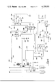
- FIG.10 is a block diagram of a further embodiment of the electrical energy cost monitor.
- FIG. 11 is a perspective view of a typical display portion of an energy cost monitor which may include both an electrical energy cost monitor and a gas cost monitor.
- FIG. 1 a perspective view of one embodiment of the present invention may be seen.
- This embodiment is intended for monitoring a utility at any desired location, independent of the usual location of the conventional utility meter.
- this embodiment is intended for convenient location for monitoring as opposed to merely occasional reading.
- the monitor may be located in the family-room or study to be most convenient for this purpose.
- the monitor of this embodiment is coupled through a line 22 to sensors which provide the basic input information with respect to the utility usage for processing and display by the monitor 20. (Details of these sensors for various utilities will be subsequently described.)
- the monitor 20 is similar in appearance to a small calculator, being characterized by a keyboard 24 and an electronic display 26.
- the keyboard 24 and electronic display 26 may be of conventional construction, with calculator keyboards and light emitting diode displays being most appropriate for this purpose.
- FIG. 2 an alternate embodiment of the present invention for monitoring the electric power consumed by a particular plug-in device is shown.
- the monitor 28 also includes conventional male and female receptacles 30 and 32, respectively.
- the unit may be temporarily coupled between a wall socket 34 and the plug of the device to be monitored to provide convenient individual device monitoring.
- the device of FIG. 2 is basically a single phase power monitor, through the concepts of the present invention may be extended to multiple phase systems, either by using appropriate plugs with a device similar to that shown in FIG. 2 for plug-in devices, or using a device similar to that of FIG. 1 for connecting through a line 22 to a multiple phase system.
- FIG. 3a a block diagram for a three wire system driving a load 36 may be seen.
- Current transformers 38 and 40 provide a measure of the current in the 0° and 180° lines, respectively, for the basic inputs to synchronous rectifiers 42 and 44.
- Voltage phase reference inputs to a synchronous rectifiers are provided by voltage taps 46 and 48, respectively so that the outputs on lines 50 and 52 are proportional to the current in the respective line times cosine ⁇ , where ⁇ is the phase angle between the voltage and current in the line.
- These two signals are summed at the summing junction 54 and filtered by filter 56 to provide a signal on line 58, as one input to the voltage controlled oscillator 60, proportional to the sum of the current in each line corrected for the power factor.
- the second input for the voltage controlled oscillator on line 62 is provided by rectifiers 64 and 66, respectively, providing signals to the summing junction 68 proportional to the voltage on the respective lines, with the sum of these two voltages being filtered by filter 70 for input to the voltage controlled oscillator.
- the output frequency on line 72 is proportional to the power, and is coupled to a programmable frequency divider 74 to provide an output on line 76 having a frequency equal to the present rate of usage of the utility. This frequency is integrated by a counter 78 for displaying as the cumulative utility usage on the display 80.
- the voltage controlled oscillator Since the programmable frequency divider 74 divides the frequency output from the voltage controlled oscillator 60, the voltage controlled oscillator is pre-set to provide an output frequency corresponding to the maximum anticipated cost per unit of the utility; in this example, the maximum anticipated cost per kilowatt-hour. Also the output of the voltage controlled oscillator is initially set to correspond to the minimum detectable power level (preferably in the area of 100 watts for most applications). In the preferred form of this embodiment, four decade switches 82 are used to program the frequency divider 74, with the digits of the switches representing the utility units per monetary unit, such as watt-hours per penny.
- the display 80 preferably a light emitting diode display, may be caused to wink at a rate proportional to the rate of usage of the utility, thereby highlighting the present rate of consumption of the utility independent of the previously accumulated consumption.
- the display 80 preferably a light emitting diode display
- FIG. 3b An embodiment utilizing the block diagram of FIG. 3a may be seen in FIG. 3b.
- This unit is characterized by a plurality of rotary switches 82 and the display 80.
- a separate clear button may be provided to clear the system as desired, or this may be achieved through the use of an on-off switch 84 (which typically is also used with the embodiments of FIGS. 1 and 2, though if a conventional calculator keyboard is utilized, a clear switch will normally be included therein).
- FIG. 4 another form of the present invention may be seen.
- This embodiment is adapted for use in power detection and accumulation for a three wire system such as in FIG. 3a, and illustrates the block diagram of the circuit which might be used with the embodiment of FIG. 1.
- current transformers 38 and 40 and voltage taps 46 and 48 are used as before, but are applied to four quadrant multipliers 86 and 88 respectively to provide the product of the voltage, current and cosine of the phase angel therebetween for each of the 0° and 180° lines on lines 90 and 92, respectively.
- a suitable four quadrant multiplier is the monlithic multiplier manufactured by Motorola Semiconductor as their part No. MC1594L.
- the outputs on lines 90 and 92 are summed at the summing junction 54 as before, filtered by filter 56, and applied to the voltage controlled oscillator 60.
- the output of the voltage controlled oscillator 60 is accumulated in a most unique way for display on the display 26.
- a calculator chip 94 having an automatic constant feature is utilized, with the output of the voltage controlled oscillator 60 causing the calculator chip 94 to successively execute summing operations, each time adding the automatic constant to the previous total to provide a new total.
- the keyboard 24, of course, is utilized to enter the automatic constant, and possibly a starting or initial charge valve.
- the automatic constant entered to the keyboard may represent the cost per unit of the utility, so that the accumulated signal displayed by display 26 represents the aggregate or accumulated cost of utility used.
- a suitable calculator chip having the automatic constant feature is that manufactured by American Microsystems, Inc.
- the display will then display the sum of this operation, with each successive depression of the equal key causing the chip to add the automatic constant to the previous total and display the new total on the display.
- an electro-mechanical depression of the key could be used, it is preferable to use some form of electronic depression, such as by way of example, turning on a transistor of field-effect device coupled in parallel with the key contacts so as to momentarily electronically provide the switch closure.
- FIG. 5 a circuit diagram for a system shown in block diagram form in FIG. 3a may be seen. Since the circuit for the 0° and 180° lines of the three-wire system are identical prior to the summing junction comprising resistors 100, only one such circuit, namely that of the 0° line is illustrated in detail, the duplication of the circuit for the 180° line being identified by the block 101.
- the current transformer 38 has a resistor 102 in parallel therewith so that the output of the transformer is a voltage in phase with and proportional to the current in the 0° line.
- the voltage in the 0° line is coupled to a relatively high valued resistor 104 to one input of a high open loop gain amplifier 106, with the other input coupled to ground.
- a pair of diodes 108 limit the differential input to approximately ⁇ 0.7 volts, with the output of amplifier 106 sensing the transition through zero and providing a square wave in phase with 0° voltage.
- the output of amplifier 106 on line 110 is coupled through diode 112 to the gate of a field-effect transistor 114.
- the square wave on line 110 turns off the field-effect device 114 during the negative half cycle of the square wave, with resistor 116 returning the gate-source voltage to zero to turn the field-effect device 114 on during the positive portion of the square wave.
- the positive input for operational amplifier 118 is coupled to ground through a resistor 120, a relatively high valued resistor in comparison to the resistor 102 in parallel with the current transformer.
- the circuit By making the feedback resistor 122 equal to resistor 124, the circuit will have a gain with respect to the signal on line 126 which alternates between +1 and -1 in response to the square wave on line 110. Accordingly, the output of the circuit on line 128 has an average value which is proportional to the current times cosine ⁇ , where ⁇ is the phase angle between the voltage and current in the first or zero degree line.
- the 0° and 180° signals are summed by the summing resistors 100 and amplified through operational amplifier 130, with the output signal thereof being filtered by the combination of resistor 132 and capacitor 134.
- the voltage appearing on line 136 is converted to an input current to the negative input terminal of operational amplifier 138 by a series resistor 140, with a feedback capacitor 142 providing current feedback from an amplifier output.
- the amplifier functions as an integrator, with the output thereof being proportional to the time integral of the voltage appearing on line 136.
- This output voltage is coupled through a resistor 144 to the positive input of amplifier 146 which serves as a threshold detector.
- the output of amplifier 146 will switch from the positive limit to the negative limit when the voltage from resistor 144 is less than the voltage on line 148, thereby pulsing field-effect device 150 ON through diode 151 to discharge the capacitor 142.
- a feedback capacitor 152 in cooperation with resistor 144 provides a sufficient pulse width in the positive going output pulse of amplifier 146 to allow substantially complete discharge of capacitor 142 through the field-effect device 150.
- the negative voltage reference on line 148 could be simply a negative voltage reference, which is conjunction with the scaling of the circuitry would provide an output pulse rate on line 154 proportional to the current times the cosine of the phase angle times a pre-determined standard voltage, such as by way of example, 110 volts.
- a first order correction for voltage variations may be provided by providing a voltage responsive reference on line 148.
- the voltages of the 0° and 180° lines are rectified by diodes 157 and summed and divided down by resistors 159 and adjustment potentiometer 160 to provide one input to operational amplifier 162 having a feedback resistor 164 and a feedback capacitor 166.
- the output voltage on line 168 is proportional to the sum of the 0° and 180° voltages. This signal is applifed through resistors 170 to one input of operational amplifier 172. This amplifier has a relatively low gain as a result of feedback resistor 174, which is approximately the same magnitude as the input resistor 170.
- the other input for amplifier 172 is a negative reference voltage provided by a resistor 176 and a Zener diode 178. Accordingly, the reference on line 148 is responsive to variations in the otherwise assumed constant supply voltage, altering the frequency of the pulse train on line 154 in response thereto.
- the pulse train on line 154 may be used to trigger a field-effect device 156 in parallel with the equal key 158 to cause the calculator chip to successively execute the summing operation to successively add the automatic constant to the running total.
- FIG. 6 a detailed circuit diagram for the embodiment of FIG. 4 may be seen.
- the current transformers 38 and 40 (See FIG. 4) provide a voltage on lines 200 and 202 proportional to the current in the 0° and 180° power phases, respectively.
- stepdown transformers 204 and 206 provides voltage signals on lines 208 and 210, respectively.
- the current signal on line 200 is applied to one input of a four quadrant multiplier 212, with the combination of resistor 214 and capacitor 216 providing attenuation of high frequency noise (having negligible energy content anyway).
- a voltage divider comprised or resistors 218 and 220 provides a further reduction in the voltage level, with capacitor 222 and resistor 224 providing similar high-frequency filtering for the voltage input of line 226 to the second input of the multiplier 212.
- the multiplier itself may be any suitable four-quadrant multiplier, though for convenience, monolithic multipliers such as the MC-1594L previously referred to are preferred as providing good performance at a low cost and in a package. (The various resistors 228 and the potentiometers 230 provide trimming, etc. in accordance with the manufacturer's recommendation for the MC-1594L).
- the multiplier 212 provides direct multiplication of the instantaneous voltage and current in the 0° phase, thereby providing an output product on line 232 equal to the instantaneous power being consumed in that phase. Since the voltage and current wave forms are 60 hz sine waves, displaced in time dependent upon the phase angle between the voltage and current in that phase (e.g. the power factor of the load), the signal (current) on line 232 will contain a substantially constant component representing the average power actually being consumed, and a twice-power frequency component (e.g. 120 hz), which component averages to zero over any full cycle.
- the output on line 232 is converted from a current to a voltage by operational amplifier 234 having an adjustable feedback through the network comprised of resistor 236 and variable resistor 238 so as to provide a gain control for the power signal on line 240 (corresponding to line 90 in FIG. 4).
- the capacitor 242 provides increased feedback for higher frequency noise components, thereby substantially attenuating those components in the signal on line 240.
- Operaational amplifier 234 is connected with the input signal on the negative input and the nulling signal on the positive input, so that the signal on line 240 actually represents the inverse or negative of the instantaneous power.
- circuitry 234 shown only in block form, for the 180° phase, resulting in a signal on line 246 representing the instantaneous power in the second phase of the power system.
- These two signals are summed by the combination of summing resistors 248 and 250, with the sum being coupled to the inverting input of operational amplifier 252.
- This amplifier has a relatively large capacitive feedback by way of capacitor 254, with a switch 256 coupled across the capacitor for dumping the charge accumulation thereof. Accordingly, the output of amplifier 252 on line 258 represents the integral of the instantaneous power in the two phases, with the integration period running from the time of last switch opening of switch 276.
- the signal on line 258 in turn is coupled through resistor 260 to the noninverting input of operational amplifier 262.
- This amplifier has a relatively small capacitor 264 providing feedback therefore, and has its inverting terminal coupled to a reference voltage source through potentiometer 266, so that the combination is operative as a comparator.
- the output on line 270 remains negative so that transistor 271 is off, thereby not energizing the relay coils 272 and 274.
- the voltage on line 258 is very quickly responsive to the charge, or lack thereof on capacitor 254 on the closing of switch 276, though the feedback capacitor 264 for amplifier 262 provides some hysteresis in the comparator, thereby holding the comparator output on line 270 positive long enough to ensure proper operation of the relays and full dumping of the charge on capacitor 254.
- scaling may be set as desired, so that each cycle of integration and dumping of the charge on capacitor 254 represents a convenient unit of energy for updating the display.
- FIG. 7 presents a block diagram of a circuit for directly reading a meter such as a watt-hour meter, a gas meter, etc.
- a wheel 282 having alternate regions of dull black and reflective portions is mounted on the shaft 280 of the basic meter movement, with the wheel 282 being illuminate by a small light source 284.
- a photodiode 286 is coupled in series with the resistor 288 to a positive voltage, with the junction therebetween coupled to the positive input of threshold detector 290.
- the resistance of the photodiode 286 is low so as to hold the noninverting input to the threshold detector 290 at a relatively low value.
- photodiode 286 has a relatively high resistance so that resistor 288 will raise the voltage to the noninverting input of the threshold detector 290 to a relatively high value.
- a voltage divider 294 provides a constant reference voltage to the inverting terminal of the threshold detector 290 so that the alternate light and dark regions of wheel 282 cause negative and positive differential input voltages, respectively, to the threshold detector.
- a relatively high value feedback resistor 296 may be used to provide a small amount of positive feedback, thereby providing some hysteresis around the switching point to avoid any uncertainty in the switching.
- the output signal on line 298 provides a direct reading of the meter movement, which may be directly used to effectively operate the equals key for the calculator chip, or if desired may be divided down by a conventional divider 299 to provide a lower frequency digital signal representative of the utility being used.
- the light source and light sensitive device may be disposed on opposite sides of the moving member and operative through an appropriate opening in the member.
- a power company charge may include a fixed periodic base charge, a first rate per kilowatt-hour up to a given consumption level for each period, and a second rate for consumption above the break point during the period.
- the base charge and break point should be alterable by the user of the device so that a device of a given design may be changed when rates are changed, and may be used for any power (utility) company regardless of their base charges, rates, and break points.
- one embodiment of the present invention utilizes a commercially available microprocessor to receive and store the basic data, and to automatically apply the base charges, break points, etc. to provide highly accurate utility monitoring throughout any charge period.
- a means 300 is provided for tracking the utility usage in quantitative terms and providing a pulse rate (repetition rate) on line 302 in direct proportion to the utility usage.
- the utility tracking means 300 might be the circuit of FIG. 6 for providing the signal on line 270, or in the alternative, the circuit shown in block digram in FIG. 3A for providing the signal on line 72.
- the repetition rate of the signal on line 302 is normalized (scaled) in some fashion, such as by way of example, for an electrical monitor a repetition rate of once per ten watt-hours of consumption is convenient.
- the microprocessor used is the F8 manufactured by the Semiconductor Components Group of the Fairchild Camera and Instrument Corp., Mountainview, Calif.
- the F8 system is believed ideal for use in this embodiment because of the ability to achieve the computational requirement with a micro-processor system comprising only two chips, in particular the 3850 central processing unit, and the 3851 program storage unit (both F8 system components).
- the 3850 central processing unit aside from providing the functions of a central processor, includes 64 bytes of scratch pad random access memory (RAM), and 16 bits of internally latched bi-directional input/output.
- the scratch pad memory provides adequate storage for the variable data needed to achieve the desired result (base rates, break points, etc.) thereby avoiding the requirement of independent RAM storage capability.
- the 3851 program storage unit provides 1024 bytes of mask programmable read-only memory (ROM) for program and constant storage, addressing logic for memory referencing, a program counter, an indirect address register (the data counter) and a stack register.
- the program storage unit includes a vectored interrupt level, with an external interrupt line to alert the central processing unit.
- the output on eight of the sixteen I/O lines are coupled to a display driver 308 driving a display 310.
- a seven-digit gas discharge display manufactured by Beckman as their SP 400 is used, with the display further including indicators 312 and 314 to provide an indication of whether the first or second rate is being applied and to indicate a memory error.
- additional indicators are driven through suitable drivers 316 from two of the additional eight I/O lines in the 3850 CPU 304.
- the additional I/O lines in the second group are coupled to a manual switch 318 to initialize the system, a reset switch 320 to reset the system for monitoring a new charge period, and to a system reset switch 322 (also coupled to the power loss detector).
- a manual switch 318 to initialize the system
- a reset switch 320 to reset the system for monitoring a new charge period
- system reset switch 322 also coupled to the power loss detector
- other inputs and/or outputs may also be incorporated if desired, such as by way of example, some form of recording device to record the accumulated consumptions upon actuation of the reset switch 320 to record the accumulated consumption immediately prior to restarting the system for the next charge period, such as a printer 321 driven by conventional printer control electronics 323, initiated by a print out switch 323.
- the function of the embodiment in FIG. 8 will be described with respect to an electrical energy monitor for monitoring electrical energy consumption for a utility having a fixed periodic charge, a first charge rate below a given break point, and a second charge rate above a given break point.
- the system is programmed so that upon pressing the initialize switch 318, the lamp is turned on for the paper tape reader 324 and the system is set for the entry of data.
- a paper tape having a suitable leader is then manually drawn through the paper tape reader 324 (which may be of conventional construction well known in the art) to sequentially enter the basic information into the system, more specifically, the high rate charge, the low rate charge, the fixed charge, and the break point between charge rates.
- a threshold value is added representing the maximum desired energy consumption above which the system will cause a flashing of the display, thereby effectively displaying not only the accumulated charge, but also the fact that the present rate exceeds a predetermined goal or allowance.
- a pulse on line 302 representing the consumption of the normalized unit of energy provides a vectored interrupt, resulting in a jump to an interrupt update routine which determines which rate should be applied based upon the energy already consumed and updates the accumulated charge by applying the proper rate to the unit of energy consumed as indicated by the pulse on line 302, increasing the total being displayed accordingly.
- the program branches to the display scan routine, maintaining the display and awaiting the next interrupt indicating the consumption of an additional unit of the utility being monitored.
- One of the features of the interrupt update routine is a capability of noting the time between interrupts, and, if that time is below a predetermined interval indicating consumption of the utility at a rate higher than a predetermined threshold, causing the display to flash.
- the threshold value is also one of the variables which is entered by the input device (in this embodiment the paper tape reader).
- the system is reset by depression of the Reset Switch 320, which for many utilities is a bimonthly cycle.
- This reset (update or bimonthly restart) enters the base charge in place of the previously accumulated total, returning to the scan mode in readiness for interrupts indicating incremental utility usage.
- the primary routines for the program are (i) an initialize routine; (ii) a display scan routine; (iii) a restart for the bimonthly reset routine; and (iv) a reset routine for manual resetting, power loss and as part of the bimonthly reset routine.
- FIG. 9 an alternate embodiment utilizing the same concepts as the embodiment of FIG. 8, but replacing the 3851 read only memory with a 3861 I/O device and incorporating a 3853 static memory interface device and an S6834 read only memory for program storage may be seen.
- the 3861 and 3853 devices are F8 family devices, and the S6834 is an 8X512 ROM manufactured by American Microsystems Inc. of Santa Clara, California.
- the interrupt and the tape reader input are directed through the I/O device 326, specifically the 3861 device, and a printer has not been included.
- the operational system is identical to that hereinbefore described with respect to FIG. 8, though the read only memory is erasable and may be altered if desired without changing any of the components of the system.
- a calculator chip is used for computational purposes, allowing the manual input of the charge rates to be used and, if desired, a base charge rate, and further having a reset capability for resetting at the end of any charge period.
- Such embodiments are particularly useful for utilities which do not have break points in the charge rate, and as an approximation for the accumulating charge for utilities having various break points, etc.
- the program itself is stored in read only memory (ROM) whereas the base charges, break points, etc., as well as the accumulated charge is stored in random access memory (RAM) on the 3850 CPU chip.
- ROM read only memory
- RAM random access memory
- a stand-by power system is provided by a power loss detection circuit 330 which detects the loss of line power and couples battery power to the 3850 (e.g., only the 3850) to maintain the random access memory during the power out condition.
- monitoring is not required in an electrical energy monitor during this time, and in order to minimize battery drain, it is generally preferable not to maintain the display during periods of power outage.
- non-volatile random access memory for the variable data and the accumulated utility usage so that power outages of indefinite periods can readily be tolerated if necessary.
- Well known core memories are one type of memory which may be used in such situations, though other suitable memories, particularly some just emerging as new developments, are also available or will shortly become available. In that regard it should be noted that with only minor modification, other tasks may readily be accomplished by the systems of the present invention, such as those of FIGS. 8 and 9.
- the system may be reset at the end of every billing period by running a suitable strip through thr reader, resulting in the printing out of the accumulated totals, preferably both in numeric figures, allowing the user to read the dollar charge directly, and in machine readable code for automatic reading at the utility company. In this manner, meter reading by the utility company is not required. Instead, the utility company may mail to each subscriber an appropriate "billing strip" for each billing period. The subscriber then simply runs the strip through a combination reader-printer assembly to read out the accumulated total and reset the system for the next billing period.
- the read-out strip and the subscriber's payment would then be forwarded to the utility company, as with any normal payment.
- the use of a non-volatile memory in such a system would provide an audit capability so that usage over an interval such as the last twelve billing periods would be retained within the unit for special reading in the event any billing strips were lost. Also, of course, simple interlocks may be incorporated so that the system may not be reset twice by the same billing strip.
- the computational capacity of the microprocessor system readily allows the inclusion of a time keeping capability, resulting in the automatic print-out and resetting of the system on a calendar basis maintained by the system itself (perhaps line frequency primarily, and crystal oscillator during power outages) to avoid irregularities in the length of each billing period.
- time keeping function of the present invention opens up other possibilities of substantial economic interest to the utility companies and subscribers alike.
- electrical energy consumption varies considerably with time of day, with certain periods having a peak power substantially higher than other periods.
- power generating and distribution systems must be capable of providing the peak power when demanded, there is a substantial cost associated with providing the capability of supplying the peak power, regardless of how long or short such demand may last during any twenty-four hour period.
- FIG. 10 a block diagram of an embodiment incorporating many of the general concepts hereinbefore discussed may be seen. It will be noted that the block diagram is separated into two portions by the dashed line 400.
- the left portion of the figure identifies the various portions of the system preferably located at the conventional site for the watt-hour meter, and the right portion of the figure identifies those portions of the system preferably located within the home or other building at a place most likely to be relatively frequently observable.
- a conventional watt-hour meter movement indicated by the numeral 402
- a light source photodetector combination generally indicated by the numeral 404, operative through an opening in the disc 406 of the meter.
- Conventional watt-hour meters with any appropriate sensing arrangement are suitable for this purpose.
- the normal dial indicators in the meters may be retained, if desired, to provide an ultimate backup in the event of malfunction of the system.
- an F-8 microprocessor system comprising the 3851 program storage unit, the 3850 central processing unit and the 3853 semiconductor memory interface unit, with a 256 ⁇ 8 CMOS random access memory 408 completing the processor elements.
- a real time clock 410 is provided so that the month of the year, day of the month and week and time of day information, preferably in fifteen minute increments, is available to the system for such purposes as the automatic print out of billing information at the end of a bill period, the adjustment of rates with time of day, and/or day of the week and the shedding of loads through a load interrupt control 412 during peak hour periods.
- auxiliary power should be provided for the clock to maintain the clock reference during any periods of power outage.
- a power supply 414 together with an auxiliary battery 416 is provided to sustain the clock 410 during power outages of up to two weeks.
- crystal controlled timing devices have sufficient accuracy for this purpose without referencing the clock to the line frequency.
- the standby power 416 is of course controlled by the power supply 414, being coupled in to sustain the random access memory 408 during power outages, the rest of the system being down during such periods.
- the power supply actually monitors line voltage, providing a signal on line 418 to the central processing unit indicative of the state of the line voltage.
- This signal is to inhibit the updating of the random access memory from the CPU whenever the line voltage is sufficiently low so as to possibly interfere with the transfer of information from the CPU to the random access memory. This assures that any updating of the random access memory, once initiated, will be completed before the system goes down on any power outage.
- three electro-mechanical counters 420, 422 and 424 are provided, each controlled by a pulse count controller 426 controlled by the 3850 CPU.
- the electro-mechanical counter 420 counts the total kilowatt-hours consumed, which of course should agree incrementally with the meter dials if left in the meter, or provide a substitute for the dials if only the fundamental watt-hour meter movement is utilized with the system.
- the additional electro-mechanical counters 422 and 424 record the total kilowatt-hours used during any designated peak period and the total kilowatt-hours consumed during any designated partial peak period respectively.
- one of the features of this embodiment of the present invention is the provision for designating one period during any twenty-four hour period during which a different rate charge may be designated, and further for designating a second period during the day during which a still different rate may be charged, these two periods being referred to as the "partial peak” and "peak” power periods.
- FIGS. 10 and 11 a block diagram and a perspective view of the portion of the system of this embodiment which is located within the home may be seen.
- the energy cost monitor shown in FIG. 11 actually monitors both gas and electricity consumption, though at this point, only the electrically monitoring portion will be described.
- the monitor contains a six digit light emitting diode display 430 for displaying the cost of electrical energy consumption in monetary indicia, the display being driven through some appropriate display driver 432 controlled by the 3850 CPU. Also visible on the front of the monitor are three lights 434, 436 and 438 representing peak power, partial peak power and off peak power periods. Obviously the off peak indicator is on only when both of the other indicators are off.
- indicator 434 will be on, the cost of the energy being consumed will be based on the peak power charge rate, and the kilowatt-hours being consumed will be accumulated both on the total accumulator 420 and on the peak kilowatt-hour accumulator 422.
- indicator 436 will be on, the cost of energy being consumed will be accumulated at the applicable partial peak rate, and the kilowatt-hours being consumed will be accumulated both on the total kilowatt-hour accumulator 420 and the partial peak kilowatt-hour accumulator 424.
- the information provided by the accumulators 420, 422, and 424 is also accumulated in memory.
- a printer 444 controlled by conventional printer control 446, and a magnetic card reader (and writer) 448 controlled by card read/write electronics 450.
- the printer uses a twelve digit thermoprint head manufactured by Toyo Electronics of Tokyo, Japan as their model number KH40, and the card reader is a model number SANAC MCP 400 manufactured by Sankyo Seiki Manufacturing Co. of Tokyo, Japan.
- the card 442 is inserted into the opening 440, it first passes under the print head and then into the reader, wherein it is retained until ejected at the end of the billing period.
- one line of numbers may be written on the card by the print head prior to the ejection of the card by the reader, with a second line being printable after the ejection (actually partial ejection) of the card so that two twelve digit lines may be written by the single line printer.
- considerable machine readable data is written ("printed") on the card during ejection, so that when mailed to the utility billing office it can be automatically processed.
- the word "print” as used herein and in the claims is used in the most general sense to include all forms of recording, whether by depositing print, change in color of the medium (thermal printer), magnetic recording, punching, etc.
- the preferred form of card is a magnetic card wherein digital data may be stored for reading (and writing) by a mag card reader (e.g. machine readable storage medium). Also, as previously mentioned, in this embodiment a printer for printing out man readable charge information is also included, printing just before card ejection and at the end of ejection, thereby printing the numeric charge information on suitable regions at each end of the mag card provided for this purpose.
- a mag card reader e.g. machine readable storage medium
- a printer for printing out man readable charge information is also included, printing just before card ejection and at the end of ejection, thereby printing the numeric charge information on suitable regions at each end of the mag card provided for this purpose.
- the first three lines on the card provide basic identification information, the first line identifying the month and the second and third lines presenting the least significant and most significant bits respectively for the subscriber identification number.
- the device is programed to check the month and the identification number so that if an incorrect card is inserted by the subscriber, either because it is not that subscriber's card or is for the wrong month, the card will be immediately ejected without reading into the system the remaining data on the card.
- the fourth and fifth line of the card identify the base charge, i.e. the monthly (or other billing cycle) fixed charge irrespective of consumption.
- the following four lines 6 through 9 identify the normal charge rate, i.e.
- Lines 10 through 13 identify the partial peak rate, with lines 14 through 17 identifying the peak rate to be charged.
- Lines 18 through 20 allow the identification of up to three holidays in the billing period (month), line 21 and 22 identify the Saturday partial peak start time and stop times respectively, lines 23 and 24 identify the Monday through Friday peak start and stop times respectively, and lines 25 and 26 identify the Monday through Friday partial peak start and stop times respectively.
- the device is programmed so that a designated peak rate period will prevail over a corresponding partial peak rate.
- a designated peak rate period will prevail over a corresponding partial peak rate.
- the Monday through Friday peak rate time is designated as 3:30 to 4:30, then partial peak rate will be applied from 2:00 to 3:30, peak rate will be applied from 3:30 to 4:30, and partial peak rate will be applied from 4:30 to 5:00, with the normal rate (lines 6 through 9) being applied for all other hours of the day.
- Lines 27 and 28 are unique to the present invention, in that they allow the identification of a specific 15 minute sample time at any time within the billing period.
- the system isolates the energy consumption for the identified sample time and prints out that information (actually in machine readable form) on the card in the output phase so that the utility may automatically gather a great deal of statistical data with respect to the energy use at the various times of the day for different types of subscribers, etc.
- Lines 29 through 34 allow the designation of an energy budget and estimated average consumption for five individual electrical loads.
- the energy budget in this embodiment is a designated maximum energy consumption during any fifteen minute period which will be allowed during the designated peak hour periods (e.g. Monday through Friday only).
- a load interrupt control 412 controls five individual loads such as, by way of example, an electric water heater, an air conditioner, a refrigerator, etc., with the average energy consumption for each of these loads being estimated in lines 30 through 34. If the energy consumed during any fifteen minute period of the designated peak rate time exceeds the budget, the system automatically sheds as many of the five loads as will be required to bring the energy consumption within the energy budget for the next 15 minute period, assuming other loads will not change.
- the final line of the card with respect to the input data is a check sum commonly used in digital equipment for error detection.
- the card When the card is received by the subscriber, it is inserted into the cost monitor whereupon the month and identification number is checked, data is read into temporary storage and the check sum is checked. If the check sum is okay, data is then loaded for use, not for the billing period then in progress, but for the next billing period coming up. At the time an individual card is inserted into the monitor, the monitor is then operating using the rate structure and holiday designation loaded by the previous card. A card once inserted and read is retained by the reader until the end of that current billing month, at which time the card will be automatically ejected, having printed thereon in man readable form the billing information for the billing period just completed, with corresponding information being printed in machine readable code. If by chance a subscriber fails to insert the card during any given billing period so that the updated rate information and holiday schedule is not available at the beginning of the next billing period, the system continues with the old billing structure, disregarding all holidays.
- each billing period the data for that billing period is printed out on the card and also stored in an audit trail file, with each month's information stored therein being moved down one month at the same time. Accordingly an audit trail is maintained directly in memory as well as in the electro-mechanical counters so that the audit trail may also be printed out each month.
- lines 1 through 9 of the machine readable print out provide the file for the current month, that is, for the billing period just completed, providing the current monthly charge in dollars in lines 1 through 3, the total kilowatt-hours in lines 4 and 5, the partial peak kilowatt-hours in lines 6 and 7, and the peak kilowatt-hours in lines 8 and 9, lines 4 through 9 effectively reproducing on the card the same information that is available on a running total rather than on a monthly basis in the electro-mechanical counters 420, 422 and 424 (see FIG. 10).
- Lines 10 through 18 of the output format provide the file for the previous month, with lines 19 through 27 providing the file for the month immediately therebefore, thereby providing a three month audit trail in the readout.
- the next month billing will be determined using the rate structure previously entered and disregarding all holidays, with a print out in machine readable form providing the audit trail so that one month's billing is not lost by the failure to insert one month's card.
- the use of a twelve digit printer printing at both ends of the card provides ample man readable print out of the billing information for the current month so that the bill is immediately presented to the subscriber for the current month, including the partial peak, peak and total kilowatt-hours, and the monetary charge, so that the card, with payment enclosed, may be returned to the utility.
- Lines 28 through 36 are available for miscellaneous information, including the date of the billing, the month of the billing, customer identification, etc., with line 28 providing the energy consumption for the fifteen minute sample period identified on the corresponding input card.
- line 37 provides the check sum. (note that, by way of example, a card mailed to a subscriber and entered into the monitor in May will carry the June rate structure, being ejected at midnight at the end of May with the May billing information thereon. Accordingly, in general, the rate structure on a particular card is not the one on which the billing information printed thereon will be based, but instead is the billing information for the immediately following billing period.
- the gas monitor is similar to at least one embodiment of the electrical monitor in that break points in the consumption of the gas may be incorporated, whereby subscribers are charged at progressively increasing rates as gas consumption for a particular billing period increases.
- the input information for a gas monitor would include a base charge, if any, and a series of rates and break points identifying the ranges of billing period consumption for which each rate will be applied.
- the charge for the billing period is displayed on display 452, with an indication of the rate being applied being provided by a series of lights 454 through 464.
- a display 466 may be provided for displaying the number of therms to the next break point.
- indicators 468 and 470 are provided for indicating when a card should be removed and a new card inserted respectively.
- Other features which may be advantageously included are various supervisory functions, accessible only by a utility representative at the conventional meter site.
- access under lock and key may be provided to a card out request switch 472 for ejecting the card within the home, such as may be desired when service is discontinued in the middle of a billing period.
- a supervisory control may be coupled to the system for such purposes as initial setting of the clock, execution of diagnostic programs and the non-destructive readout of current files.
- any suitable sensor operative from the conventional meter movement may be used, or a separate flow rate monitor may be provided for this purpose.
- an input signal comprising a parallel reading of the meter dials rather than a rate input may be used, or any combination of rate and amount input signals may be used as an input to the cost monitors indicative of the rate of usage of the utility.
- microprocessor as used herein and in the appended claims, except as used specifically with respect to the F8 microprocessor is used in the broad sense to designate digital computational devices generally, whether general purpose or dedicated, and whether programmable, microprogrammable or hardwired, the F8 merely being an example of a general purpose programmable microprocessor.
Landscapes
- Business, Economics & Management (AREA)
- Engineering & Computer Science (AREA)
- Physics & Mathematics (AREA)
- General Physics & Mathematics (AREA)
- Theoretical Computer Science (AREA)
- Strategic Management (AREA)
- Health & Medical Sciences (AREA)
- Economics (AREA)
- General Business, Economics & Management (AREA)
- Marketing (AREA)
- Primary Health Care (AREA)
- Tourism & Hospitality (AREA)
- Public Health (AREA)
- Water Supply & Treatment (AREA)
- Human Resources & Organizations (AREA)
- General Health & Medical Sciences (AREA)
- Microelectronics & Electronic Packaging (AREA)
- Computer Networks & Wireless Communication (AREA)
- Accounting & Taxation (AREA)
- Indication And Recording Devices For Special Purposes And Tariff Metering Devices (AREA)
Abstract
Description
Claims (71)
Applications Claiming Priority (1)
| Application Number | Priority Date | Filing Date | Title |
|---|---|---|---|
| US70667976A | 1976-07-19 | 1976-07-19 |
Related Parent Applications (1)
| Application Number | Title | Priority Date | Filing Date |
|---|---|---|---|
| US70667976A Continuation-In-Part | 1976-07-19 | 1976-07-19 |
Publications (1)
| Publication Number | Publication Date |
|---|---|
| US4120031A true US4120031A (en) | 1978-10-10 |
Family
ID=24838626
Family Applications (1)
| Application Number | Title | Priority Date | Filing Date |
|---|---|---|---|
| US05/810,675 Expired - Lifetime US4120031A (en) | 1976-07-19 | 1977-06-27 | Utility usage monitoring systems |
Country Status (1)
| Country | Link |
|---|---|
| US (1) | US4120031A (en) |
Cited By (99)
| Publication number | Priority date | Publication date | Assignee | Title |
|---|---|---|---|---|
| US4207557A (en) * | 1977-05-20 | 1980-06-10 | Blose John B | User electric energy consumption apparatus |
| US4229795A (en) * | 1977-10-21 | 1980-10-21 | Siemens Aktiengesellschaft | Electronic maximum measuring device |
| US4233590A (en) * | 1978-02-27 | 1980-11-11 | Gilkeson Robert F | Supplemental energy register |
| US4236217A (en) * | 1979-04-20 | 1980-11-25 | Kennedy Stanley P | Energy utilization or consumption recording arrangement |
| US4253151A (en) * | 1978-11-03 | 1981-02-24 | Bouve Thomas T | Apparatus for monitoring and controlling consumer power consumption |
| US4254472A (en) * | 1978-08-14 | 1981-03-03 | The Valeron Corporation | Remote metering system |
| US4261037A (en) * | 1979-04-03 | 1981-04-07 | Dupont Energy Management Corporation | System for monitoring utility usage |
| US4283772A (en) * | 1979-03-30 | 1981-08-11 | Westinghouse Electric Corp. | Programmable time registering AC electric energy meter having electronic accumulators and display |
| US4291375A (en) * | 1979-03-30 | 1981-09-22 | Westinghouse Electric Corp. | Portable programmer-reader unit for programmable time registering electric energy meters |
| US4291376A (en) * | 1979-08-08 | 1981-09-22 | Three Rivers Enterprises, Inc. | Digital energy monitor |
| WO1981003541A1 (en) * | 1980-06-06 | 1981-12-10 | I Joensson | Microprocessor based energy consumption meter |
| US4314201A (en) * | 1980-04-14 | 1982-02-02 | Dynamic Instrument Corporation | Power measuring apparatus |
| US4317175A (en) * | 1979-11-13 | 1982-02-23 | Massachusetts Institute Of Technology | Dynamic rate integrating demand monitor |
| US4335437A (en) * | 1980-04-15 | 1982-06-15 | Westinghouse Electric Corp. | Circuit interrupter with energy management functions |
| US4345311A (en) * | 1979-01-11 | 1982-08-17 | South Eastern Electricity Board | Electronic kilowatt-hour meter for measuring electrical energy consumption |
| US4351028A (en) * | 1979-02-21 | 1982-09-21 | South Eastern Electricity Board | Meters for measuring electrical energy consumption |
| WO1982003482A1 (en) * | 1981-04-06 | 1982-10-14 | Dupont Energy | System for monitoring utility usage |
| US4361872A (en) * | 1977-12-29 | 1982-11-30 | Lgz Landis & Gyr Zug Ag | Measuring apparatus for determining the effective value of the power demand of an energy consumer over a period of calculation |
| US4370723A (en) * | 1980-01-31 | 1983-01-25 | Peak Demand Limiters, Inc. | Computerized energy management system |
| US4399510A (en) * | 1979-04-03 | 1983-08-16 | Nuclear Systems, Inc. | System for monitoring utility usage |
| US4405987A (en) * | 1977-12-29 | 1983-09-20 | Lgz Landis & Gyr Zug Ag | Measuring processes and apparatus for determining tariff values for energy consumers |
| US4415853A (en) * | 1978-09-08 | 1983-11-15 | Fisher Berish M | Monitoring device and method for accurately determining and recording present demand of electrical energy |
| US4449187A (en) * | 1982-07-30 | 1984-05-15 | Scott Charles F | Device for indirectly monitoring cumulative cost of utility consumption |
| GB2133594A (en) * | 1982-12-24 | 1984-07-25 | Leslie Taylor | Electrical power consumption costing device |
| US4465970A (en) * | 1981-02-26 | 1984-08-14 | General Electric Company | Method and apparatus for multiple rate metering of electrical energy |
| US4509128A (en) * | 1982-04-16 | 1985-04-02 | Sangamo Weston, Inc. | Solid-state electrical-power demand register and method |
| EP0107466A3 (en) * | 1982-10-19 | 1986-10-15 | Hawker Siddeley Revenue Controls Limited | A product-accessing system |
| US4630211A (en) * | 1984-04-23 | 1986-12-16 | Pettis Charles D | Watt-hour meter display for informing consumer of energy consumption |
| US4783623A (en) * | 1986-08-29 | 1988-11-08 | Domestic Automation Company | Device for use with a utility meter for recording time of energy use |
| US4792677A (en) * | 1986-08-29 | 1988-12-20 | Domestic Automation Company, Inc. | System for use with a utility meter for recording time of energy use |
| US4814996A (en) * | 1982-06-10 | 1989-03-21 | Futures Technology, Ltd. | Portable energy cost calculation |
| US4924404A (en) * | 1988-04-11 | 1990-05-08 | K. Reinke, Jr. & Company | Energy monitor |
| USD310973S (en) | 1986-08-29 | 1990-10-02 | Domestic Automation Company Inc. | Device for use with utility meters to record time of energy use, demand and load profile data |
| US5153837A (en) * | 1990-10-09 | 1992-10-06 | Sleuth Inc. | Utility consumption monitoring and control system |
| US5287287A (en) * | 1990-09-14 | 1994-02-15 | Energy Audit Corporation | Power consumption rate display device |
| US5315236A (en) * | 1991-03-05 | 1994-05-24 | Lee Graham S | Power consumption meter for displaying electric power consumed by appliance and the time period of consumption |
| GB2282904A (en) * | 1993-10-16 | 1995-04-19 | Larrie Kevin Rowbottom | Domestic energy information system |
| US5420799A (en) * | 1991-08-15 | 1995-05-30 | Eaton Corporation | Circuit breaker - associated backpack unit for lower-link communication with a PC computer monitoring system and energy monitoring system using a plurality of such backpack units |
| US5495167A (en) * | 1994-07-12 | 1996-02-27 | General Electric Company | Electrical energy meter having record of meter calibration data therein and method of recording calibration data |
| US5537029A (en) * | 1992-02-21 | 1996-07-16 | Abb Power T&D Company Inc. | Method and apparatus for electronic meter testing |
| ES2107934A1 (en) * | 1994-07-28 | 1997-12-01 | Blanco Benito Roman Guerrero | Active electrical energy meter with user-programmable charging device. |
| ES2111468A1 (en) * | 1995-07-27 | 1998-03-01 | Infrarrojo Y Microelectronica | Micro-meter for managing electricity consumption. |
| US5732193A (en) * | 1909-01-26 | 1998-03-24 | Aberson; Michael | Method and apparatus for behavioristic-format coding of quantitative resource data/distributed automation protocol |
| US5869960A (en) * | 1996-12-19 | 1999-02-09 | Brand; Ethan | Digital power consumption meter for displaying instantaneous and consumed electric power of an electrical device |
| US6147484A (en) * | 1998-07-08 | 2000-11-14 | Smith; Richard T. | Device for measuring power using switchable impedance |
| US6360177B1 (en) | 1992-11-10 | 2002-03-19 | Shenandoah Electronic Intelligence, Inc. | Voltage scanning, measurement, storage and reporting device |
| US6374188B1 (en) | 1996-10-22 | 2002-04-16 | Abb Automation Inc. | Energy meter with instrumentation systems and methods |
| US20020082748A1 (en) * | 2000-06-15 | 2002-06-27 | Internet Energy Systems, Inc. | Utility monitoring and control systems |
| US20020091653A1 (en) * | 1997-12-19 | 2002-07-11 | Michael R. Peevey | Method and apparatus for metering electricity usage and electronically providing information associated therewith |
| US6429643B1 (en) | 1998-07-08 | 2002-08-06 | Southwest Research Institute | Device for measuring power using switchable impedance |
| US6476592B1 (en) * | 1997-10-30 | 2002-11-05 | Humlum Energy Consult A/S | Device and a method of metering and displaying energy consumption and a method of calibrating the device |
| US20030036918A1 (en) * | 2000-12-20 | 2003-02-20 | Pintsov Leon A. | System and method for trusted self-billing and payment for utilities including audit, verification, reconciliation and dispute resolution |
| WO2003102831A1 (en) * | 2002-05-31 | 2003-12-11 | Hotav Limited | Monitoring usage of electronic equipment |
| US20040161085A1 (en) * | 1998-12-07 | 2004-08-19 | Horne Gregory L. | Caller ID system with restransmitted caller ID information |
| US20040169500A1 (en) * | 2003-03-01 | 2004-09-02 | Mr. Johnnyson Jones | Kilowatt-hour Counter Using An ADI ADE7755 |
| US20050270173A1 (en) * | 2003-02-14 | 2005-12-08 | Boaz Jon A | Automated meter reading system, communication and control network for automated meter reading, meter data collector program product, and associated methods |
| US20050275371A1 (en) * | 2004-06-15 | 2005-12-15 | Bersiek Shamel A | Current monitor |
| GB2416852A (en) * | 2004-08-07 | 2006-02-08 | Zoe Edwards | Power consumption cost monitoring device |
| US7003769B1 (en) * | 1999-08-31 | 2006-02-21 | Fujitsu Limited | System diagnosis apparatus, system diagnosis method and computer-readable recording medium recording system diagnosis program |
| US7043380B2 (en) | 2003-09-16 | 2006-05-09 | Rodenberg Iii Ernest Adolph | Programmable electricity consumption monitoring system and method |
| US20070001868A1 (en) * | 2003-02-14 | 2007-01-04 | Boaz Jon A | Automated meter reading system, communication and control network for automated meter reading, meter data collector, and associated methods |
| US20070013547A1 (en) * | 2003-02-14 | 2007-01-18 | Boaz Jon A | Automated meter reading system, communication and control network from automated meter reading, meter data collector, and associated methods |
| US20070037441A1 (en) * | 2005-08-15 | 2007-02-15 | Onstott Richard S | Layman's electrical assistant |
| US7180282B2 (en) | 1992-02-21 | 2007-02-20 | Elster Electricity, Llc | Apparatus for metering at least one type of electrical power over a predetermined range of service voltages |
| US20070200553A1 (en) * | 2006-02-10 | 2007-08-30 | Roger Morrison | Electrical profile monitoring system for detection of atypical consumption |
| WO2007143834A1 (en) * | 2006-06-13 | 2007-12-21 | John Alan Gibson | Electrical energy monitor |
| US7355867B2 (en) | 2004-08-17 | 2008-04-08 | Elster Electricity, Llc | Power supply for an electric meter having a high-voltage regulator that limits the voltage applied to certain components below the normal operating input voltage |
| WO2008092268A1 (en) * | 2007-02-02 | 2008-08-07 | Aztech Associates Inc. | Utility monitoring device, system and method |
| US20090119039A1 (en) * | 2007-11-07 | 2009-05-07 | Sproutlets, Inc. | Approach for Controlling Electrical Power |
| US7540767B1 (en) | 2006-08-25 | 2009-06-02 | Reliance Controls Corporation | Plug-in amp/watt power meter |
| US20090289501A1 (en) * | 2008-04-22 | 2009-11-26 | Belkin International, Inc. | Power supply |
| US20100156632A1 (en) * | 2008-10-27 | 2010-06-24 | Mueller International, Inc. | Infrastructure monitoring system and method |
| US20110153108A1 (en) * | 2009-12-18 | 2011-06-23 | Electronics And Telecommunications Research Institute | Method and device for remote power management |
| US20110160913A1 (en) * | 2009-12-31 | 2011-06-30 | Schneider Electric USA, Inc. | Methods and apparatuses for displaying energy savings from an hvac system |
| US20110163600A1 (en) * | 2010-01-05 | 2011-07-07 | Belkin International, Inc. | Power supply and method related thereto |
| US20110166839A1 (en) * | 2011-02-10 | 2011-07-07 | Christian Smith | Method and system for the estimating the energy consumption of commercially available electrical devices |
| US20110187552A1 (en) * | 2010-02-04 | 2011-08-04 | Belkin International, Inc. | Ground Detection Circuit and Method of Manufacturing the Same |
| US20110304876A1 (en) * | 2010-06-15 | 2011-12-15 | Xerox Corporation | System and printing device for monitoring and modifying operation of a printing device corresponding to electrical energy consumption |
| US20120004785A1 (en) * | 2010-07-02 | 2012-01-05 | Lsis Co., Ltd. | Energy control apparatus and method |
| US8115476B1 (en) | 2009-06-15 | 2012-02-14 | Reliance Controls Corporation | Apparatus for providing energy usage and energy cost data for an electrical device |
| US20120262153A1 (en) * | 2011-03-17 | 2012-10-18 | National Cheng Kung University | Apparatus and method for measuring electrical parameters of circuit |
| US20130035884A1 (en) * | 2011-08-04 | 2013-02-07 | William Jerome Burke | Apparatus and method for sub-metering of household devices |
| US20130060395A1 (en) * | 2011-09-02 | 2013-03-07 | Hunt Energy Iq, Lp | Automated field provisioning for energy management systems |
| US8407333B2 (en) | 2002-11-18 | 2013-03-26 | Mueller International, Llc | Method and apparatus for inexpensively monitoring and controlling remotely distributed appliances |
| US20130197831A1 (en) * | 2012-01-31 | 2013-08-01 | Yoshiaki Yonezawa | Fluid flow rate measuring device and water meter |
| US8587148B2 (en) | 2008-04-22 | 2013-11-19 | Belkin International, Inc. | Electric power supply and related methods |
| US8660134B2 (en) | 2011-10-27 | 2014-02-25 | Mueller International, Llc | Systems and methods for time-based hailing of radio frequency devices |
| US8823509B2 (en) | 2009-05-22 | 2014-09-02 | Mueller International, Llc | Infrastructure monitoring devices, systems, and methods |
| US8833390B2 (en) | 2011-05-31 | 2014-09-16 | Mueller International, Llc | Valve meter assembly and method |
| US8855569B2 (en) | 2011-10-27 | 2014-10-07 | Mueller International, Llc | Systems and methods for dynamic squelching in radio frequency devices |
| US20140320665A1 (en) * | 2013-04-25 | 2014-10-30 | Bacsoft Ltd. | System for reading a meter |
| US8931505B2 (en) | 2010-06-16 | 2015-01-13 | Gregory E. HYLAND | Infrastructure monitoring devices, systems, and methods |
| US20150073736A1 (en) * | 2013-09-09 | 2015-03-12 | Xerox Corporation | Method and system for automated association of devices with electricity meters |
| US9494249B2 (en) | 2014-05-09 | 2016-11-15 | Mueller International, Llc | Mechanical stop for actuator and orifice |
| US9565620B2 (en) | 2014-09-02 | 2017-02-07 | Mueller International, Llc | Dynamic routing in a mesh network |
| US9852486B2 (en) | 2007-02-02 | 2017-12-26 | Aztech Associates Inc. | Utility monitoring device, system and method |
| US10180414B2 (en) | 2013-03-15 | 2019-01-15 | Mueller International, Llc | Systems for measuring properties of water in a water distribution system |
| US11041839B2 (en) | 2015-06-05 | 2021-06-22 | Mueller International, Llc | Distribution system monitoring |
| US11725366B2 (en) | 2020-07-16 | 2023-08-15 | Mueller International, Llc | Remote-operated flushing system |
Citations (12)
| Publication number | Priority date | Publication date | Assignee | Title |
|---|---|---|---|---|
| US3046534A (en) * | 1959-10-05 | 1962-07-24 | Jr Paul C Constant | Remote meter reading apparatus |
| US3416075A (en) * | 1959-03-11 | 1968-12-10 | Electrometre | Fixed quantity apparatus for metering the consumption by a consumer of electricity or the like supplied over a common supply network and for processing the data representing such consumption |
| US3502980A (en) * | 1965-11-19 | 1970-03-24 | Albert Jefferies | Digital maximum demand indicator for electric power consumption |
| US3590220A (en) * | 1967-09-27 | 1971-06-29 | Mitsubishi Electric Corp | Apparatus for determining the amount of a product consumed between two time periods |
| US3634663A (en) * | 1969-02-25 | 1972-01-11 | Westinghouse Electric Corp | Remote reading measuring system |
| US3747068A (en) * | 1971-11-04 | 1973-07-17 | Sangamo Electric Co | Remote meter reading system for kwh watthour meters and demand meters |
| US3842248A (en) * | 1972-08-17 | 1974-10-15 | L Prince | Utilities meter readout system |
| US3932730A (en) * | 1973-05-02 | 1976-01-13 | Electronic Memories & Magnetics Corporation | Point-of-action billing transactor |
| US3937937A (en) * | 1973-12-26 | 1976-02-10 | Xerox Corporation | Primary power fault detector |
| US3946220A (en) * | 1974-06-10 | 1976-03-23 | Transactron, Inc. | Point-of-sale system and apparatus |
| US3950759A (en) * | 1975-01-08 | 1976-04-13 | Bethlehem Steel Corporation | Portable instrument for recording electrical load current and operating duration |
| US3998093A (en) * | 1975-04-07 | 1976-12-21 | Kelsey-Hayes Company | Energy monitoring system |
-
1977
- 1977-06-27 US US05/810,675 patent/US4120031A/en not_active Expired - Lifetime
Patent Citations (12)
| Publication number | Priority date | Publication date | Assignee | Title |
|---|---|---|---|---|
| US3416075A (en) * | 1959-03-11 | 1968-12-10 | Electrometre | Fixed quantity apparatus for metering the consumption by a consumer of electricity or the like supplied over a common supply network and for processing the data representing such consumption |
| US3046534A (en) * | 1959-10-05 | 1962-07-24 | Jr Paul C Constant | Remote meter reading apparatus |
| US3502980A (en) * | 1965-11-19 | 1970-03-24 | Albert Jefferies | Digital maximum demand indicator for electric power consumption |
| US3590220A (en) * | 1967-09-27 | 1971-06-29 | Mitsubishi Electric Corp | Apparatus for determining the amount of a product consumed between two time periods |
| US3634663A (en) * | 1969-02-25 | 1972-01-11 | Westinghouse Electric Corp | Remote reading measuring system |
| US3747068A (en) * | 1971-11-04 | 1973-07-17 | Sangamo Electric Co | Remote meter reading system for kwh watthour meters and demand meters |
| US3842248A (en) * | 1972-08-17 | 1974-10-15 | L Prince | Utilities meter readout system |
| US3932730A (en) * | 1973-05-02 | 1976-01-13 | Electronic Memories & Magnetics Corporation | Point-of-action billing transactor |
| US3937937A (en) * | 1973-12-26 | 1976-02-10 | Xerox Corporation | Primary power fault detector |
| US3946220A (en) * | 1974-06-10 | 1976-03-23 | Transactron, Inc. | Point-of-sale system and apparatus |
| US3950759A (en) * | 1975-01-08 | 1976-04-13 | Bethlehem Steel Corporation | Portable instrument for recording electrical load current and operating duration |
| US3998093A (en) * | 1975-04-07 | 1976-12-21 | Kelsey-Hayes Company | Energy monitoring system |
Cited By (151)
| Publication number | Priority date | Publication date | Assignee | Title |
|---|---|---|---|---|
| US5732193A (en) * | 1909-01-26 | 1998-03-24 | Aberson; Michael | Method and apparatus for behavioristic-format coding of quantitative resource data/distributed automation protocol |
| US4207557A (en) * | 1977-05-20 | 1980-06-10 | Blose John B | User electric energy consumption apparatus |
| US4229795A (en) * | 1977-10-21 | 1980-10-21 | Siemens Aktiengesellschaft | Electronic maximum measuring device |
| US4361872A (en) * | 1977-12-29 | 1982-11-30 | Lgz Landis & Gyr Zug Ag | Measuring apparatus for determining the effective value of the power demand of an energy consumer over a period of calculation |
| US4405987A (en) * | 1977-12-29 | 1983-09-20 | Lgz Landis & Gyr Zug Ag | Measuring processes and apparatus for determining tariff values for energy consumers |
| US4233590A (en) * | 1978-02-27 | 1980-11-11 | Gilkeson Robert F | Supplemental energy register |
| US4254472A (en) * | 1978-08-14 | 1981-03-03 | The Valeron Corporation | Remote metering system |
| US4415853A (en) * | 1978-09-08 | 1983-11-15 | Fisher Berish M | Monitoring device and method for accurately determining and recording present demand of electrical energy |
| US4253151A (en) * | 1978-11-03 | 1981-02-24 | Bouve Thomas T | Apparatus for monitoring and controlling consumer power consumption |
| US4345311A (en) * | 1979-01-11 | 1982-08-17 | South Eastern Electricity Board | Electronic kilowatt-hour meter for measuring electrical energy consumption |
| US4351028A (en) * | 1979-02-21 | 1982-09-21 | South Eastern Electricity Board | Meters for measuring electrical energy consumption |
| US4291375A (en) * | 1979-03-30 | 1981-09-22 | Westinghouse Electric Corp. | Portable programmer-reader unit for programmable time registering electric energy meters |
| US4283772A (en) * | 1979-03-30 | 1981-08-11 | Westinghouse Electric Corp. | Programmable time registering AC electric energy meter having electronic accumulators and display |
| US4261037A (en) * | 1979-04-03 | 1981-04-07 | Dupont Energy Management Corporation | System for monitoring utility usage |
| US4399510A (en) * | 1979-04-03 | 1983-08-16 | Nuclear Systems, Inc. | System for monitoring utility usage |
| US4236217A (en) * | 1979-04-20 | 1980-11-25 | Kennedy Stanley P | Energy utilization or consumption recording arrangement |
| US4291376A (en) * | 1979-08-08 | 1981-09-22 | Three Rivers Enterprises, Inc. | Digital energy monitor |
| US4317175A (en) * | 1979-11-13 | 1982-02-23 | Massachusetts Institute Of Technology | Dynamic rate integrating demand monitor |
| US4370723A (en) * | 1980-01-31 | 1983-01-25 | Peak Demand Limiters, Inc. | Computerized energy management system |
| US4314201A (en) * | 1980-04-14 | 1982-02-02 | Dynamic Instrument Corporation | Power measuring apparatus |
| US4335437A (en) * | 1980-04-15 | 1982-06-15 | Westinghouse Electric Corp. | Circuit interrupter with energy management functions |
| WO1981003541A1 (en) * | 1980-06-06 | 1981-12-10 | I Joensson | Microprocessor based energy consumption meter |
| US4465970A (en) * | 1981-02-26 | 1984-08-14 | General Electric Company | Method and apparatus for multiple rate metering of electrical energy |
| WO1982003482A1 (en) * | 1981-04-06 | 1982-10-14 | Dupont Energy | System for monitoring utility usage |
| US4509128A (en) * | 1982-04-16 | 1985-04-02 | Sangamo Weston, Inc. | Solid-state electrical-power demand register and method |
| US4814996A (en) * | 1982-06-10 | 1989-03-21 | Futures Technology, Ltd. | Portable energy cost calculation |
| US4449187A (en) * | 1982-07-30 | 1984-05-15 | Scott Charles F | Device for indirectly monitoring cumulative cost of utility consumption |
| EP0107466A3 (en) * | 1982-10-19 | 1986-10-15 | Hawker Siddeley Revenue Controls Limited | A product-accessing system |
| GB2133594A (en) * | 1982-12-24 | 1984-07-25 | Leslie Taylor | Electrical power consumption costing device |
| US4630211A (en) * | 1984-04-23 | 1986-12-16 | Pettis Charles D | Watt-hour meter display for informing consumer of energy consumption |
| US4792677A (en) * | 1986-08-29 | 1988-12-20 | Domestic Automation Company, Inc. | System for use with a utility meter for recording time of energy use |
| USD310973S (en) | 1986-08-29 | 1990-10-02 | Domestic Automation Company Inc. | Device for use with utility meters to record time of energy use, demand and load profile data |
| US4783623A (en) * | 1986-08-29 | 1988-11-08 | Domestic Automation Company | Device for use with a utility meter for recording time of energy use |
| US4924404A (en) * | 1988-04-11 | 1990-05-08 | K. Reinke, Jr. & Company | Energy monitor |
| US5287287A (en) * | 1990-09-14 | 1994-02-15 | Energy Audit Corporation | Power consumption rate display device |
| US5153837A (en) * | 1990-10-09 | 1992-10-06 | Sleuth Inc. | Utility consumption monitoring and control system |
| US5315236A (en) * | 1991-03-05 | 1994-05-24 | Lee Graham S | Power consumption meter for displaying electric power consumed by appliance and the time period of consumption |
| US5420799A (en) * | 1991-08-15 | 1995-05-30 | Eaton Corporation | Circuit breaker - associated backpack unit for lower-link communication with a PC computer monitoring system and energy monitoring system using a plurality of such backpack units |
| US5537029A (en) * | 1992-02-21 | 1996-07-16 | Abb Power T&D Company Inc. | Method and apparatus for electronic meter testing |
| US6762598B1 (en) | 1992-02-21 | 2004-07-13 | Elster Electricity, Llc | Method for providing optical test signals for electronic meter testing |
| US20050270015A1 (en) * | 1992-02-21 | 2005-12-08 | Elster Electricity, Llc | Method and apparatus for electronic meter testing |
| US7339805B2 (en) | 1992-02-21 | 2008-03-04 | Elster Electricity, Llc | Power supply having voltage blocking clamp |
| US6954061B2 (en) | 1992-02-21 | 2005-10-11 | Elster Electricity, Llc | Method and apparatus for electronic meter testing |
| US6703823B1 (en) * | 1992-02-21 | 2004-03-09 | Elster Electricity, Llc | Method and apparatus for electronic meter testing |
| US20040008019A1 (en) * | 1992-02-21 | 2004-01-15 | Hemminger Rodney C. | Method and apparatus for electronic meter testing |
| US7180282B2 (en) | 1992-02-21 | 2007-02-20 | Elster Electricity, Llc | Apparatus for metering at least one type of electrical power over a predetermined range of service voltages |
| US6504357B1 (en) | 1992-02-21 | 2003-01-07 | Abb Automation Inc. | Apparatus for metering electrical power and electronically communicating electrical power information |
| US6483290B1 (en) | 1992-02-21 | 2002-11-19 | Abb Automation Inc. | Apparatus for metering electrical power that determines energy usage data based on downloaded information |
| US7239125B2 (en) | 1992-02-21 | 2007-07-03 | Elster Electricity, Llc | Method and apparatus for electronic meter testing |
| US6360177B1 (en) | 1992-11-10 | 2002-03-19 | Shenandoah Electronic Intelligence, Inc. | Voltage scanning, measurement, storage and reporting device |
| GB2282904A (en) * | 1993-10-16 | 1995-04-19 | Larrie Kevin Rowbottom | Domestic energy information system |
| GB2282904B (en) * | 1993-10-16 | 1998-09-16 | Larrie Kevin Rowbottom | Energy indicator |
| US5495167A (en) * | 1994-07-12 | 1996-02-27 | General Electric Company | Electrical energy meter having record of meter calibration data therein and method of recording calibration data |
| ES2107934A1 (en) * | 1994-07-28 | 1997-12-01 | Blanco Benito Roman Guerrero | Active electrical energy meter with user-programmable charging device. |
| ES2111468A1 (en) * | 1995-07-27 | 1998-03-01 | Infrarrojo Y Microelectronica | Micro-meter for managing electricity consumption. |
| US6507794B1 (en) | 1996-10-22 | 2003-01-14 | Abb Automation Inc. | Energy meter with power quality monitoring systems and methods |
| US6577961B1 (en) | 1996-10-22 | 2003-06-10 | Abb Automation Inc. | Energy meter having programmable functions |
| US6374188B1 (en) | 1996-10-22 | 2002-04-16 | Abb Automation Inc. | Energy meter with instrumentation systems and methods |
| US5869960A (en) * | 1996-12-19 | 1999-02-09 | Brand; Ethan | Digital power consumption meter for displaying instantaneous and consumed electric power of an electrical device |
| US6476592B1 (en) * | 1997-10-30 | 2002-11-05 | Humlum Energy Consult A/S | Device and a method of metering and displaying energy consumption and a method of calibrating the device |
| US20020091653A1 (en) * | 1997-12-19 | 2002-07-11 | Michael R. Peevey | Method and apparatus for metering electricity usage and electronically providing information associated therewith |
| US7043459B2 (en) * | 1997-12-19 | 2006-05-09 | Constellation Energy Group, Inc. | Method and apparatus for metering electricity usage and electronically providing information associated therewith |
| US6147484A (en) * | 1998-07-08 | 2000-11-14 | Smith; Richard T. | Device for measuring power using switchable impedance |
| US6429643B1 (en) | 1998-07-08 | 2002-08-06 | Southwest Research Institute | Device for measuring power using switchable impedance |
| US7266187B2 (en) | 1998-12-07 | 2007-09-04 | Curio, Ltd. | Caller ID system with retransmitted caller ID information |
| US20070253543A1 (en) * | 1998-12-07 | 2007-11-01 | Curio, Ltd. | Caller ID system with retransmitted caller ID information |
| US20040161085A1 (en) * | 1998-12-07 | 2004-08-19 | Horne Gregory L. | Caller ID system with restransmitted caller ID information |
| US7953214B2 (en) | 1998-12-07 | 2011-05-31 | Curio Ltd. | Caller ID system with retransmitted caller ID information |
| US7003769B1 (en) * | 1999-08-31 | 2006-02-21 | Fujitsu Limited | System diagnosis apparatus, system diagnosis method and computer-readable recording medium recording system diagnosis program |
| US20020082748A1 (en) * | 2000-06-15 | 2002-06-27 | Internet Energy Systems, Inc. | Utility monitoring and control systems |
| US7415431B2 (en) * | 2000-12-20 | 2008-08-19 | Pintsov Leon A | System and method for trusted self-billing and payment for utilities including audit, verification, reconciliation and dispute resolution |
| US20030036918A1 (en) * | 2000-12-20 | 2003-02-20 | Pintsov Leon A. | System and method for trusted self-billing and payment for utilities including audit, verification, reconciliation and dispute resolution |
| GB2406640B (en) * | 2002-05-31 | 2006-01-25 | Hotav Ltd | Monitoring usage of electronic equipment |
| US20050240417A1 (en) * | 2002-05-31 | 2005-10-27 | Dave Savage | Monitoring usage of electronic equipment |
| GB2406640A (en) * | 2002-05-31 | 2005-04-06 | Hotav Ltd | Monitoring usage of electronic equipment |
| WO2003102831A1 (en) * | 2002-05-31 | 2003-12-11 | Hotav Limited | Monitoring usage of electronic equipment |
| US8407333B2 (en) | 2002-11-18 | 2013-03-26 | Mueller International, Llc | Method and apparatus for inexpensively monitoring and controlling remotely distributed appliances |
| US8549131B2 (en) | 2002-11-18 | 2013-10-01 | Mueller International, Llc | Method and apparatus for inexpensively monitoring and controlling remotely distributed appliances |
| US20070013547A1 (en) * | 2003-02-14 | 2007-01-18 | Boaz Jon A | Automated meter reading system, communication and control network from automated meter reading, meter data collector, and associated methods |
| US20070001868A1 (en) * | 2003-02-14 | 2007-01-04 | Boaz Jon A | Automated meter reading system, communication and control network for automated meter reading, meter data collector, and associated methods |
| US7304587B2 (en) | 2003-02-14 | 2007-12-04 | Energy Technology Group, Inc. | Automated meter reading system, communication and control network for automated meter reading, meter data collector program product, and associated methods |
| US7400264B2 (en) | 2003-02-14 | 2008-07-15 | Energy Technology Group, Inc. | Automated meter reading system, communication and control network for automated meter reading, meter data collector, and associated methods |
| US20050270173A1 (en) * | 2003-02-14 | 2005-12-08 | Boaz Jon A | Automated meter reading system, communication and control network for automated meter reading, meter data collector program product, and associated methods |
| US20040169500A1 (en) * | 2003-03-01 | 2004-09-02 | Mr. Johnnyson Jones | Kilowatt-hour Counter Using An ADI ADE7755 |
| US7043380B2 (en) | 2003-09-16 | 2006-05-09 | Rodenberg Iii Ernest Adolph | Programmable electricity consumption monitoring system and method |
| US20050275371A1 (en) * | 2004-06-15 | 2005-12-15 | Bersiek Shamel A | Current monitor |
| GB2416852A (en) * | 2004-08-07 | 2006-02-08 | Zoe Edwards | Power consumption cost monitoring device |
| US7355867B2 (en) | 2004-08-17 | 2008-04-08 | Elster Electricity, Llc | Power supply for an electric meter having a high-voltage regulator that limits the voltage applied to certain components below the normal operating input voltage |
| US20070037441A1 (en) * | 2005-08-15 | 2007-02-15 | Onstott Richard S | Layman's electrical assistant |
| US7402993B2 (en) * | 2006-02-10 | 2008-07-22 | Dtechs Epm Ltd. | Electrical profile monitoring system for detection of atypical consumption |
| US20070200553A1 (en) * | 2006-02-10 | 2007-08-30 | Roger Morrison | Electrical profile monitoring system for detection of atypical consumption |
| WO2007143834A1 (en) * | 2006-06-13 | 2007-12-21 | John Alan Gibson | Electrical energy monitor |
| US7540767B1 (en) | 2006-08-25 | 2009-06-02 | Reliance Controls Corporation | Plug-in amp/watt power meter |
| US7677921B2 (en) | 2006-08-25 | 2010-03-16 | Reliance Controls Corporation | Plug-in amp/watt power meter |
| US9852486B2 (en) | 2007-02-02 | 2017-12-26 | Aztech Associates Inc. | Utility monitoring device, system and method |
| WO2008092268A1 (en) * | 2007-02-02 | 2008-08-07 | Aztech Associates Inc. | Utility monitoring device, system and method |
| US8325057B2 (en) | 2007-02-02 | 2012-12-04 | Aztech Associates, Inc. | Utility monitoring device, system and method |
| CN101765758B (en) * | 2007-02-02 | 2011-08-31 | 阿芝台克联合公司 | Utility monitoring device, system and method |
| US9171458B2 (en) | 2007-02-02 | 2015-10-27 | Aztech Associates, Inc. | Utility monitoring device, system and method |
| US20090119039A1 (en) * | 2007-11-07 | 2009-05-07 | Sproutlets, Inc. | Approach for Controlling Electrical Power |
| US20090289501A1 (en) * | 2008-04-22 | 2009-11-26 | Belkin International, Inc. | Power supply |
| US8587148B2 (en) | 2008-04-22 | 2013-11-19 | Belkin International, Inc. | Electric power supply and related methods |
| US8232683B2 (en) | 2008-04-22 | 2012-07-31 | Belkin International, Inc. | Relocatable power tap |
| US9202362B2 (en) | 2008-10-27 | 2015-12-01 | Mueller International, Llc | Infrastructure monitoring system and method |
| US9934670B2 (en) | 2008-10-27 | 2018-04-03 | Mueller International, Llc | Infrastructure monitoring system and method |
| US10262518B2 (en) | 2008-10-27 | 2019-04-16 | Mueller International Llc | Method of disseminating monitoring information relating to contamination and corrosion within an infrastructure |
| US20100156632A1 (en) * | 2008-10-27 | 2010-06-24 | Mueller International, Inc. | Infrastructure monitoring system and method |
| US9799204B2 (en) | 2009-05-22 | 2017-10-24 | Mueller International, Llc | Infrastructure monitoring system and method and particularly as related to fire hydrants and water distribution |
| US8823509B2 (en) | 2009-05-22 | 2014-09-02 | Mueller International, Llc | Infrastructure monitoring devices, systems, and methods |
| US8115476B1 (en) | 2009-06-15 | 2012-02-14 | Reliance Controls Corporation | Apparatus for providing energy usage and energy cost data for an electrical device |
| US20110153108A1 (en) * | 2009-12-18 | 2011-06-23 | Electronics And Telecommunications Research Institute | Method and device for remote power management |
| US20110160913A1 (en) * | 2009-12-31 | 2011-06-30 | Schneider Electric USA, Inc. | Methods and apparatuses for displaying energy savings from an hvac system |
| US8352082B2 (en) | 2009-12-31 | 2013-01-08 | Schneider Electric USA, Inc. | Methods and apparatuses for displaying energy savings from an HVAC system |
| US20110163600A1 (en) * | 2010-01-05 | 2011-07-07 | Belkin International, Inc. | Power supply and method related thereto |
| US8890372B2 (en) | 2010-01-05 | 2014-11-18 | Belkin International, Inc. | Power supply and method related thereto |
| US8742943B2 (en) | 2010-02-04 | 2014-06-03 | Belkin International, Inc. | Ground detection circuit and method of manufacturing the same |
| US20110187552A1 (en) * | 2010-02-04 | 2011-08-04 | Belkin International, Inc. | Ground Detection Circuit and Method of Manufacturing the Same |
| US20110304876A1 (en) * | 2010-06-15 | 2011-12-15 | Xerox Corporation | System and printing device for monitoring and modifying operation of a printing device corresponding to electrical energy consumption |
| US8717594B2 (en) | 2010-06-15 | 2014-05-06 | Xerox Corporation | System for monitoring and modifying operation of an electrical energy consuming device corresponding to electrical energy consumption |
| US8570564B2 (en) * | 2010-06-15 | 2013-10-29 | Xerox Corporation | System and printing device for monitoring and modifying operation of a printing device corresponding to electrical energy consumption |
| US9861848B2 (en) | 2010-06-16 | 2018-01-09 | Mueller International, Llc | Infrastructure monitoring devices, systems, and methods |
| US9849322B2 (en) | 2010-06-16 | 2017-12-26 | Mueller International, Llc | Infrastructure monitoring devices, systems, and methods |
| US8931505B2 (en) | 2010-06-16 | 2015-01-13 | Gregory E. HYLAND | Infrastructure monitoring devices, systems, and methods |
| US8855831B2 (en) * | 2010-07-02 | 2014-10-07 | Lsis Co., Ltd. | Energy control apparatus and method |
| US20120004785A1 (en) * | 2010-07-02 | 2012-01-05 | Lsis Co., Ltd. | Energy control apparatus and method |
| US20110166839A1 (en) * | 2011-02-10 | 2011-07-07 | Christian Smith | Method and system for the estimating the energy consumption of commercially available electrical devices |
| US8172147B2 (en) * | 2011-02-10 | 2012-05-08 | Christian Smith | Method and system for the estimating the energy consumption of commercially available electrical devices |
| US20120262153A1 (en) * | 2011-03-17 | 2012-10-18 | National Cheng Kung University | Apparatus and method for measuring electrical parameters of circuit |
| US9063169B2 (en) * | 2011-03-17 | 2015-06-23 | National Cheng Kung University | Apparatus and method for measuring electrical parameters of circuit |
| US8833390B2 (en) | 2011-05-31 | 2014-09-16 | Mueller International, Llc | Valve meter assembly and method |
| US8949051B2 (en) * | 2011-08-04 | 2015-02-03 | General Electric Company | Apparatus and method for sub-metering of household devices |
| US20130035884A1 (en) * | 2011-08-04 | 2013-02-07 | William Jerome Burke | Apparatus and method for sub-metering of household devices |
| US20130060395A1 (en) * | 2011-09-02 | 2013-03-07 | Hunt Energy Iq, Lp | Automated field provisioning for energy management systems |
| US10039018B2 (en) | 2011-10-27 | 2018-07-31 | Mueller International, Llc | Systems and methods for recovering an out-of-service node in a hierarchical network |
| US8660134B2 (en) | 2011-10-27 | 2014-02-25 | Mueller International, Llc | Systems and methods for time-based hailing of radio frequency devices |
| US8855569B2 (en) | 2011-10-27 | 2014-10-07 | Mueller International, Llc | Systems and methods for dynamic squelching in radio frequency devices |
| US10156463B2 (en) * | 2012-01-31 | 2018-12-18 | Semiconductor Components Industries, Llc | Fluid flow rate measuring device and water meter |
| US20130197831A1 (en) * | 2012-01-31 | 2013-08-01 | Yoshiaki Yonezawa | Fluid flow rate measuring device and water meter |
| US11255835B2 (en) | 2013-03-15 | 2022-02-22 | Mueller International, Llc | Systems for measuring properties of water in a water distribution system |
| US10180414B2 (en) | 2013-03-15 | 2019-01-15 | Mueller International, Llc | Systems for measuring properties of water in a water distribution system |
| US10203315B2 (en) | 2013-03-15 | 2019-02-12 | Mueller International Llc | Systems for measuring properties of water in a water distribution system |
| US11307190B2 (en) | 2013-03-15 | 2022-04-19 | Mueller International, Llc | Systems for measuring properties of water in a water distribution system |
| US12253507B2 (en) | 2013-03-15 | 2025-03-18 | Mueller International, Llc | Systems for measuring properties of water in a water distribution system |
| US20140320665A1 (en) * | 2013-04-25 | 2014-10-30 | Bacsoft Ltd. | System for reading a meter |
| US20150073736A1 (en) * | 2013-09-09 | 2015-03-12 | Xerox Corporation | Method and system for automated association of devices with electricity meters |
| US10663497B2 (en) * | 2013-09-09 | 2020-05-26 | Xerox Corporation | Method and system for automated association of devices with electricity meters |
| US9494249B2 (en) | 2014-05-09 | 2016-11-15 | Mueller International, Llc | Mechanical stop for actuator and orifice |
| US9565620B2 (en) | 2014-09-02 | 2017-02-07 | Mueller International, Llc | Dynamic routing in a mesh network |
| US11041839B2 (en) | 2015-06-05 | 2021-06-22 | Mueller International, Llc | Distribution system monitoring |
| US11725366B2 (en) | 2020-07-16 | 2023-08-15 | Mueller International, Llc | Remote-operated flushing system |
| US12385233B2 (en) | 2020-07-16 | 2025-08-12 | Mueller International, Llc | Fluid flushing system |
Similar Documents
| Publication | Publication Date | Title |
|---|---|---|
| US4120031A (en) | Utility usage monitoring systems | |
| US4516213A (en) | Multiple rate metering system | |
| US4399510A (en) | System for monitoring utility usage | |
| US4908769A (en) | Commodity metering systems | |
| US6762598B1 (en) | Method for providing optical test signals for electronic meter testing | |
| US4291375A (en) | Portable programmer-reader unit for programmable time registering electric energy meters | |
| EP0335912B1 (en) | Prepayment metering system using encoded purchase cards | |
| US4467434A (en) | Solid state watt-hour meter | |
| GB2046925A (en) | Programmable time registering ac electric energy meter having electronic accumulators and display | |
| US4621330A (en) | Programming system for programmable time registering electric energy meters | |
| US3502980A (en) | Digital maximum demand indicator for electric power consumption | |
| JPS61172068A (en) | electricity meter | |
| EP0092436B1 (en) | Improved apparatus for the collection of payments for commodities | |
| GB2095879A (en) | Cost display device | |
| US4654588A (en) | Time-of-use watt-hour meter with demand profile capability | |
| GB2220975A (en) | Water metering system | |
| EP0219577A1 (en) | Device for controlling delivery of a utility | |
| AU7371981A (en) | System for monitoring utility usage | |
| KR20030035296A (en) | Digital power meter of calculating the used power according to ratio which allocated to time band | |
| GB2136613A (en) | Data recorder with non-volatile solid state memory | |
| US4754217A (en) | Seasonal reset for electric watthour meter registers | |
| JPS58500338A (en) | Multi-rate electrical energy metering device | |
| US5115190A (en) | Freezing items for display in electronic watthour register | |
| US20040124828A1 (en) | Device and method for continuously monitoring energy usage | |
| CN111175554A (en) | Three-phase fee-control intelligent electric meter with code scanning transaction function |
Legal Events
| Date | Code | Title | Description |
|---|---|---|---|
| AS | Assignment |
Owner name: ENERGY CONSERVATION SYSTEMS INC., Free format text: LETTERS OF ADMINISTRATION;ASSIGNOR:TECHNOLOGY ASSOCIATES;REEL/FRAME:003922/0265 Effective date: 19811027 |
|
| AS | Assignment |
Owner name: ENERGY CONSERVATION SYSTEMS, INC., 3118 AIRWAY AVE Free format text: OPTION;ASSIGNOR:TECHNOLOGY ASSOCIATES, A CORP. OF CA.;REEL/FRAME:003972/0705 Effective date: 19820107 |
|
| AS | Assignment |
Owner name: SCHLUMBERGER RESOURCE MANAGEMENT SYSTEMS, INC., GE Free format text: ASSIGNMENT OF ASSIGNORS INTEREST;ASSIGNOR:CELLNET DATA SYSTEMS, INC.;REEL/FRAME:010871/0652 Effective date: 20000516 |
|
| AS | Assignment |
Owner name: SCHLUMBERGER RESOURCE MANAGEMENT SERVICES, INC., G Free format text: RECORD OT CORRECT ASSIGNEE NAME ON DOCUMENT PREVIOUSLY RECORDED AT REEL 010871,FRAME 0652;ASSIGNOR:CELLNET DATA SYSTEMS, INC.;REEL/FRAME:015044/0904 Effective date: 20000516 Owner name: SCHLUMBERGER RESOURCE MANAGEMENT SERVICES, INC., G Free format text: CORRECTIVE ASSIGNMENT TO CORRECT ASSIGNEE NAME ON DOCUMENT PREVIOUSLY RECORDED AT REEL 010871,FRAME 0652;ASSIGNOR:CELLNET DATA SYSTEMS, INC.;REEL/FRAME:015044/0904 Effective date: 20000516 |