US3942975A - Method and apparatus for reducing matter to constituent elements and separating one of the elements from the other elements - Google Patents
Method and apparatus for reducing matter to constituent elements and separating one of the elements from the other elements Download PDFInfo
- Publication number
- US3942975A US3942975A US05/269,634 US26963472A US3942975A US 3942975 A US3942975 A US 3942975A US 26963472 A US26963472 A US 26963472A US 3942975 A US3942975 A US 3942975A
- Authority
- US
- United States
- Prior art keywords
- specie
- ionized
- separating
- magnetic field
- gas
- Prior art date
- Legal status (The legal status is an assumption and is not a legal conclusion. Google has not performed a legal analysis and makes no representation as to the accuracy of the status listed.)
- Expired - Lifetime
Links
Images


Classifications
-
- C—CHEMISTRY; METALLURGY
- C22—METALLURGY; FERROUS OR NON-FERROUS ALLOYS; TREATMENT OF ALLOYS OR NON-FERROUS METALS
- C22B—PRODUCTION AND REFINING OF METALS; PRETREATMENT OF RAW MATERIALS
- C22B4/00—Electrothermal treatment of ores or metallurgical products for obtaining metals or alloys
- C22B4/005—Electrothermal treatment of ores or metallurgical products for obtaining metals or alloys using plasma jets
Definitions
- This invention relates to a method and apparatus for reducing matter to constituent elements and separating the elements each from the other. More particularly, the invention relates to a method and apparatus for reducing compounds, such as metal oxides, to constituent elements and separating a desired element (e.g., aluminum from oxygen) using high temperature plasmas.
- a desired element e.g., aluminum from oxygen
- the degree of ionization at a particular temperature varies from element to element.
- the ionization potential of aluminum is about 5.98eV and that of oxygen is about 13.61eV.
- the practical effect of differing ionization potential and other factors e.g., degeneracy of the lowest ionized state
- certain elements of high ionization potential do not ionize appreciably at the temperatures where significant ionization of other elements takes place.
- Examination of the equilibrium composition of a gaseous mixture at elevated temperatures demonstrates that, for certain compounds, after disassociation, one element is partially ionized but the other element or elements are not significantly ionized.
- the degree of ionization is a monotonically increasing function of temperature.
- the present separation process and apparatus operates upon a gas containing only one significantly ionized specie. Separation using only partial ionization means that lower temperatures can be used. Lower temperatures mean less energy input. Analysis shows that throughout rates of production for the selected specie are little affected by ionization fractions as low as several percent. This means that the process is operated at very small percentages of ionization (1-2%) and therefore significantly lower enthalpy relative to those processes which require full ionization (Varney U.S. Pat. No. 1,954,900) while still producing greater quantities of the selected specie. This is made practical by the very rapid (resonant) exchange of charge between atoms and ions of a single specie.
- the invented process separates the partly ionized specie from the essentially un-ionized species using a magnetic field. It has been found that a magnetic field at an angle to the direction of flow of the partly ionized gas generates a separating force that operates well at plasma pressures so high that fluid flow rather than molecular flow exists. This is in contrast to the case with the Varney patent. This, together with the large flow velocities permitted produces large throughput rates.
- the separator uses an externally generated magnetic field through which the entire plasma including the ions, the electrons and the neutral elements are allowed to flow. More particularly, a magnetic field is oriented at an angle such that it has been perpendicular and parallel components relative to the plasma flow velocity. The interaction of the perpendicular component with the plasma flow velocity produces a current density having both magnitude and direction. The interaction of the current density and the parallel magnetic field component produces a separating force upon the ions and the neutral elements of the same specie that is perpendicular to the plasma velocity. So that a destructive space charge is not built up, the current is allowed to close upon itself. For this, a structure having axial symmetry is provided. The net result is a separating force on the entirety of the partly ionized specie.
- the degree of separation could be made very high by proper design because it was based upon the percentage of thermal ionization of one gas component over another.
- the active force causes a separation that is proportional to the fractional mass differences of the components to be separated; but in the Columbia device, separation is proportional to an exponential of the ionization potential difference. This is because the percentage ionization is determined by a Boltzmann factor which has the ionization potential in an exponent. The nature of this is such that a factor of two difference in ionization potential can result in a factor of one hundred difference in percentage ionization.
- the present invention recognizes that the principle of separation using ionization potential differences is valid. Indeed, existing electrolytic separation processes, such as the separation of alumina, Al 2 O 3 , are forms of separation by ionization.
- the effective ionization potentials of the components to be separated are lowered by the use of a special electrolyte which in the case of alumina is Cryolite.
- the ionization potential of aluminum is 5.98eV while that of oxygen is 13.61eV.
- the aluminum becomes positively ionized.
- a voltage is applied to the electrolyte cell and the positive ions are forced through it in one direction.
- the negative ions are forced to move in the opposite direction.
- the present invention is directed toward separating one element from another.
- metals are separated from their compounds; i.e., aluminum from alumina (Al 2 O 3 ).
- Al 2 O 3 alumina
- the invention is not limited to instances in which only the partly ionized specie is to be recovered.
- the invention is a separation process. This means that the un-ionized specie or species may be recovered as the primary output of the process.
- the invention is applicable to separating an element and chemical compound from each other if that is the manner in which the input compound dissociates and there is partial ionization of the element.
- the principal advantage of the invented process and apparatus is in separating certain metals from the more electronegative elements, oxygen in particular, but also sulphur and silicon. These elements do not ionize appreciably at the temperatures where significant ionization of the metals takes place.
- the most common and economical process in current use for a wide variety of metals is to separate the metal element from its ore by chemical treatments yielding usually an oxide, and then reducing the oxide with carbon.
- the plasma reduction process which forms this invention takes the place of reducing the oxide with carbon since complete separation from other metallic elements is not generally possible by this invention.
- Certain other elements such as the metals found in the III and IV columns of the periodic table tend to form stable carbides so that reduction to purer metals by carbon is not possible. Examples are aluminum (III), titanium (IV) and zirconium (IV).
- Aluminum silicate is a more widely available source of aluminum ore than Al 2 O 3 . It is normally found in the form of clay. In aluminum silicate at 5,000°K and one atmosphere of pressure aluminum ions are more than one thousand times as abundant as silicon ions. Accordingly, the present invention provides a means whereby abundant aluminum silicate clays may become a source of fairly pure aluminum metal whereas they had not been so in the past.
- Titanium is commonly prepared by converting it to titanium tetrachloride and then purifying the tetrachloride by fractional distillation.
- the purified tetrachloride is reduced with magnesium or sodium. It is the reduction process which is the most expensive and which makes titanium a relatively expensive metal even though it is one of the most abundant metals in the earth's crust.
- the present invention has the advantage of being able to reduce titanium tetrachloride without the use of magnesium or sodium residues.
- Use of the present invention for the reduction of titanium oxide is feasible although difficult because TiO is very stable.
- Zirconium is manufactured by essentially the same process as titanium. Pure zirconium tetrachloride is prepared and then reduced. The present invention can be used to reduce zirconium tetrachloride.
- the present invention takes advantage of the concept that certain metal elements are at least partly ionized at temperatures where there is no significant ionization of the more electronegative elements such as oxygen, sulphur and silicon which combine to make up their ores.
- This provides a means whereby the ionized metals can be separated from their compounds.
- the negative charge carriers are electrons rather than ions.
- a simple gaseous electrolytic cell cannot be used for separation. For each positive aluminum ion that would be collected at the cathode about 50,000 electrons would reach the anode. (In the conventional liquid electrolytic cell only about one negative ion is collected for each useful positive ion.) This creates a difficult separation problem. If the electrons are prevented from flowing, a space charge will build up to such an extent that the ionic current will be drawn across a high voltage. This more than offsets the energy advantage gained in removing the cryolite through which the ions had to be forced.
- any current I flowing in a region having a magnetic field B experiences a force I ⁇ B at right angles to I. So the electrons are forced in a new direction by their current. If the electric current is prevented from flowing in this direction, the electrons will begin to pile up and the space charge voltage will pull the ions toward them. Then they will both move in the I ⁇ B direction with the speed proportional to the large electron current and inversely proportional to the mobility of the ions and the hot gas.
- Electrodes as in the conventional electrolytic cell.
- the problem with electrodes is that of joule heating as a source of inefficiency as well as electrode wear both in the electrode and in the connecting wires. In the present invention this is avoided because the ions are moving in the same I ⁇ B direction as the electrons so that there need be no current through surfaces and no corresponding joule heating and wear.
- the direction of the magnetic field is significant.
- a parallel magnetic field can be used to separate the ions from neutral particles since charged particles spiral around magnetic field lines, whereas neutral particles are unaffected. This works very efficiently but very slowly because low pressures are required to avoid deleterious collisions.
- a magnetic field at an angle to the flow generates a separating force that operates well at high plasma pressures and large flow velocities so that large throughputs are possible.
- the separation concept uses both perpendicular and parallel magnetic field components.
- a magnetic field is oriented at an angle ⁇ relative to the plasma flow velocity v. Accordingly, the magnetic field has a perpendicular component B.sub.
- with v produces a current density J.
- the interaction of J and B.sub. ⁇ produces a separating force F which is perpendicular to v.
- the current is allowed to close upon itself so that space charges do not build up. For this reason, a structure having axial symmetry is provided.
- the separating force is either inward or outward and depends upon the direction of the magnetic field.
- the present invention is described primarily in respect to separating metals from their compounds, it should be understood that the principles apply equally to separating any element which is a constituent part of a particular type of matter where one element can be at least partly ionized in a gaseous phase without substantially ionizing the other element or elements which comprise the matter.
- the invention is also applicable to separating a non-ionized species from two or more ionized species of the compound. That partially ionized element together with the neutral particles of the same element can be separated using the principles of the separator described herein.
- the matter is heated to a gaseous phase wherein the one element (specie) is at least partly ionized.
- the gas is then passed at an angle through a magnetic field and at a high velocity. Both the ionized and neutral particles of the partly ionized element are forced toward a collection point as hereinafter described.
- a principle advantage of the invention is that separation is achieved even though ionization is only partial. Indeed, production rate is independent of percent ionization above a few tenths of a percent. This means less energy is required to effect the separation. No more energy need be put in than is required to dissociate and partly ionize one specie element at about 1-2%.
- Another advantage of the invention is that separation takes place at moderate pressures, such as .5 atmospheres, rather than low pressures such as ⁇ 0.001 Atm. This permits high throughput rates making the process economically feasible for the amount of energy put in.
- FIG. 1 is a schematic diagram of the invented process.
- FIG. 2 is a sectional view of the apparatus.
- FIG. 3 is a sectional view of another embodiment of the apparatus.
- FIG. 4 is a graph showing the equilibrium composition of Al 2 O 3 at 1 atmosphere.
- FIG. 5 is a graph showing the equilibrium composition of Fe 2 O 3 at 1 atmosphere.
- FIG. 6 is a graph showing the equilibrium composition of CuO at 1 atmosphere.
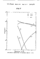
- FIG. 7 is a graph showing the equilibrium composition of NiO at 1 atmosphere.
- FIG. 8 is a graph showing the equilibrium composition of SnO 2 at 1 atmosphere.
- FIG. 9 is a graph showing the equilibrium composition of FeNiS 4 at 1 atmosphere.
- FIG. 10 is a graph showing the equilibrium composition of Al 2 SiO 5 at 1 atmosphere.
- FIG. 11 plots a Hartmann number against the dimensionless pressure gradient.
- FIG. 12 is a graph schematically illustrating the interrelationship of current density, magnetic field and force density.
- FIG. 13 is a sectional view of an arc heater.
- FIG. 14 is a partial sectional view of a wall.
- FIG. 15 is a partial sectional view of another embodiment of a wall.
- FIG. 16 is a partial sectional view of yet another embodiment of a wall.
- Varney U.S. Pat. No. 1,954,900 is an interesting early example of a process for reducing metallic ores by separating ionized vapors.
- a metallic compound is heated and ionized by an arc passing between two electrodes.
- a magnet drives the arc and the ionized gas from a reduction chamber to a condensing chamber or receptacle. Separation is accomplished by relying upon velocity, mass and gravity. Thus, the higher velocity particles fall by gravity into a different portion of the wall of the horizontally positioned collecting receptacle than do the slower velocity particles.
- the present invention separates a selected specie element from the remaining elements in the matter being processed using principles of magnetofluid dynamics.
- the principal aspects of the process are heating the matter from which a specie element is to be separated until the matter dissociates into a gaseous state and is at a temperature at which such specie element is partly ionized. At such temperature the remaining elements have no significant ionization and hence may be regarded as neutral.
- the gas and plasma is passed at a high velocity through a magnetic field having both parallel and perpendicular components relative to the direction of flow.
- the process is schematically illustrated in FIG. 1.
- the matter, including the specie element to be separated, is fed into the heater, vaporizer and ionizer 10 driven by an appropriate source of power.
- the matter then passes from the heater, vaporizer and ionizer 10 to the separator 12 where the partly ionized specie element is separated from the other elements of the matter.
- the separator 12 is energized to the extent necessary by an appropriate source of power which in the described embodiment is electrical and mechanical power.
- the specie element as shown, is taken from the separator while by-products consisting of the remaining matter are appropriately processed in by-product and recycling devices 14. As described hereinafter, it is desirable to recycle some of the by-products to assist, by way of heat transfer, in the heating and ionization process. Excess heat could also be used to drive appropriate thermal engines.
- Heaters, vaporizers and ionizers for accomplishing the heating and partial ionization process are described infra. Separators and the basic separating process are described in this section. The by-product and recycling processes are not described herein except that insofar as recycling of oxygen for heat exchange and calcining are set forth hereinafter. In yet another section, processes and apparatus for containing the hot gases are described.
- FIG. 2 there is shown an apparatus for partly ionizing one element in a compound and then separating the partly ionized element from the remaining elements of the compound.
- Aluminum is specifically referred to hereinafter. However, it should be understood that the principles apply generally to compounds where only one specie is ionized.
- the apparatus includes means 16 and 18 for feeding the compound into the vaporizers 19 and 20 described hereafter. The specific manner in which the compound 20 is fed into the vaporizers is not part of the present invention. Hence, it need not be described in detail.
- the vaporized compound passes from the vaporizers 19 and 20 into the arc heaters 22 and 24, provided with an appropriate cooling means. This compound is further heated until it dissociates into a gas consisting of the dissociated constituent elements. Although only two arc heaters 22 and 24 are shown, it should be understood that additional heaters may be positioned around the periphery of the top of the separator 26 for feeding the desired amount of gaseous material into the apparatus.
- the vaporized and dissociated compound is further heated to ionization temperature by arcs 23 and 25 positioned within the magnetic field B. If desired ionization can be accomplished using a radio frequency field rather than the arcs 23 and 25. Ionization must take place within the magnetic field. Otherwise, the ionized particles will not enter into it.
- the separator 26 is positioned immediately below the arc heaters 22 and 24 and, as shown, comprises a structure having a generally frusto-conical interior wall 28.
- the gas pressure generated in the arc heaters 22 and 24 feed the plasma into the separator 26 at an angle and velocity generally parallel to the wall 28 such that gaseous plasma flows with the appropriate velocity along the wall and at an angle ⁇ to the magnetic field B generated by the magnetic coil 30.
- Magnetic coil 30 is of the super conductive type (cryogenic) so as to be capable of generating a magnetic field of the appropriate field strength as hereinafter more specifically described.
- the wall structure 28 of the separator 26 may be made of porous material (preferably the same as the ore) through which is forced liquid, or liquid metal, or a combination of them (e.g., liquid aluminum, liquid alumina, or a combination of liquid aluminum and liquid alumina) for transpiration cooling as more particularly described hereinafter in Section V.
- the wall could also be alumina which is allowed to vaporize and is replaced from time to time or continuously.
- the separated metal condenses on the lower portion of the wall structure 28 and flows down into the annular receptacle 32 where it is collected, and from which it may be tapped off through the outlet 34.
- a slag 38 is shown floating above the metal 36 within the receptacle 32.
- Dense slag 39 is shown at the bottom of receptacle 32.
- the outlet 40 is provided for exhausting and recycling by-product gases and other matter from which the metal has been separated.
- by-product gases will consist primarily of oxygen as, by way of example, in the case of separating aluminum from Al 2 O 3 and iron from Fe 2 O 3 .
- FIG. 2 The structure shown in FIG. 2 can be modified such that plasma and gas flow along the outer surface of a cone.
- the separation process works equally well and a central ionizer at the apex of the cone could be used.
- FIG. 3 there is illustrated yet another apparatus embodying the principles of the invention.
- a compound such as alumina
- the means for feeding the compound into the channels 48 and 50 does not form a part of the present invention and hence is not described in detail. Additional feed means, as desired, may be provided.
- the compound moving at a high velocity, is deflected by deflector 52 into the melting section 54 where it is melted and heated to a temperature close to the boiling point of the compound.
- the compound is heated to this condition by a heat exchange process with oxygen fed back from the separator after the aluminum has been removed from the gas. As shown, the fed back oxygen impinges upon the oxygen deflector 58 so that it flows over and past the particles to heat and melt the same.
- the deflectors 52 and 58 also serve to guide the oxygen into chamber 62 from which it is exhausted through port 64 to a heat engine, calcining plant, or the like.
- the vaporization of the compound is illustrated in FIG. 3 by showing it in particle form in the region 66. In the region 68 it is illustrated in its liquid form by depicting droplets.
- the liquified compound moves at a high velocity into the separating section 76. At the top of this section it is vaporized and ionized by plasma torches 84 and 86.
- the annular channel through which the gaseous vapors are directed is conical, as defined by the annular wall 78 and the outer wall 80. This causes the gaseous vapor to flow at an angle to the magnetic field B generated by the super conductive magnetic coil 82.
- the liquified compound is heated so as to provide vaporization and the requisite partial ionization of the selected element to be separated from the other elements by means of plasma jets positioned at the head of the conical channel defined by the walls 78 and 80.
- the plasma jets are generated by plasma torches 84 and 86 driven by an appropriate source of electrical power.
- Such torches may be three phase alternating current torches which can be operated at 90% thermal efficiency to produce gases at temperatures of 5,400°K-7,000°K.
- a rotating arc process for vaporizating and partially ionizing may augment the plasma torches. Such rotating arc is illustrated in FIG. 13 and described in Section IV, infra.
- the magnetic coil 82 is preferably a solenoid which surrounds the entire conical annular channel 77 and generates a magnetic field B parallel to the axis of the apparatus.
- the length of the coil 82 is such that ionization takes place within the magnetic field.
- and the parallel magnetic field component B.sub. ⁇ acts upon the ionized element to drive it toward one of the walls 78 or 80. Since the magnetic field B is mostly in the direction of flow of the ionized element and such flow is angled inwardly toward the axis of the apparatus, the partially ionized element is driven and therefore diffuses toward the outer wall 80 and flows downward to be collected in the receptacle 88. A slag 90 is shown floating on the top surface of the liquid metal 92. The liquid metal may be tapped out of the receptacle 88 via conduit 94.
- the remaining elements of the gaseous vapors such as oxygen in the case of separating aluminum from alumina, returns through the center of the annular wall 78 as indicated by the arrows. From there it is conducted to the deflector 58 for a heat exchange with the incoming metal ore as described previously.
- the walls of the apparatus are appropriately cooled either by convective cooling or transpiration cooling as described in more detail in Section V.
- Ablative walls may also be used. So as not to unduly complicate the description of the invention, such cooling means are not shown in FIG. 3.
- the walls are preferably made of the same material as the matter being reduced.
- the walls may be made of sintered alumina when separating aluminum.
- the recirculating oxygen or other gaseous matter will also revaporize some of the slag 90 and conduct it through the apparatus where it will again become entrained with the incoming particles and be recycled for further separation of the selected element.
- FIG. 4 is the equilibrium composition of Al 2 O 3 at one atmosphere. Note that 2% ionization occurs at approximately 5,000°K in FIG. 4.
- FIG. 5 is the equilibrium composition of Fe 2 O 3 at one atmosphere.
- FIG. 6 is the equilibrium composition of CuO at one atmosphere.
- FIG. 7 is the equilibrium composition of NiO at one atmosphere.
- FIG. 8 is the equilibrium composition of SnO at one atmosphere.
- FIG. 9 is the equilibrium composition of FeS 2 .NiS 2 at one atmosphere.
- FIG. 10 is the equilibrium composition Al 2 SiO 5 at one atmosphere. The temperature at which between 1-10% ionization takes place is easily read from these graphs.
- the process is applicable to raw are as mined.
- the only treatment necessary is grinding and drying.
- the only exception to this would be the unexpected situation where an ore includes significant quantities of an element having an ionization potential at or lower than the ionization potential of the element sought. In that instance further separation by flotation or chemical treatment to remove the unwanted element may be necessary.
- the invention is based upon the fact that the selected specie element, such as aluminum ions (Al+), is the major ionic species in a gaseous mixture between 5,000°K and 10,000°K. Since the cross section of charge exchange between an atom and an ion of the same element is very large, each selected specie element has a high probability of being ionized within a short period of time.
- the selected specie element e.g., Al with Al+
- a chamber is provided in which a continuously generated ring of mixed plasma (partly ionized specie) and gas is forced to flow along the surface of a cone in an axial-magnetic field.
- mixed plasma partly ionized specie
- gas is forced to flow along the surface of a cone in an axial-magnetic field.
- plasma is used throughout this specification. As used herein, it is intended to mean that portion of an ionized gas or vapor of such extent that within it static charges are statistically screened by charges of opposite sign and of small extent compared to the extent of the gas.
- FIG. 2 shows the separator 26 with a conical wall 28. It is fed with an input of aluminum and oxygen in which at least part of the aluminum is ionized (Al+).
- the coil 30 provides a uniform magnetic field B having the direction indicated by the arrow. The flow of the plasma and gas is parallel to the wall 28 of the separator 26 and hence at an angle ⁇ to the magnetic field B.
- the hot gases flow along the conical wall gas and
- the flow channel 77 is defined by walls 78 and 80.
- the width of the flow channel is defined by the inlet from the arc heater 22 and 24.
- the gas is moving at a velocity v less than the speed of sound and at an angle ⁇ to the magnetic field B.
- the magnetic field is produced by the coil 30 (a super conducting solenoid in a liquid helium bath) and is nearly uniform over the cross section of the separator 26.
- the hot gas plasma move along the chamber wall, a large current carried primarily by the electrons is produced.
- the electrons exist by virtue of having been pulled off of the aluminum atoms.
- the electrons flow around the axis of the separator by reason of the fact that they are being forced to move at right angles to the perpendicular component of the magnetic field B.sub.
- This force density F is either radially in or out. If the plasma is travelling down a converging conical path, as shown in FIG. 2, the force is, by Lenz's law, outward. If the conical path is a diverging one, the force F would be such as to oppose that and hence would be radially inward.
- FIG. 2 the electrons are diffusing toward the wall 28 of the separator 26. As they start to move, an electric field arises due to the separation between the ions (Al+) and the electrons. This radial field pulls the ions after the electrons toward the wall surface 28 where they flow into the receptacle 32.
- the foregoing relationships between the magnetic field B, the current density J and the force F density is shown in FIG. 12. Note that the force is everywhere outward.
- ⁇ is the resistivity of the gas and plasma.
- the resonant charge exchange is important to the fulfillment of the process.
- the resonant charge transfer cross section is approximately 10 - 14 cm 2 . This means that a given atom changes its ionization state approximately 10 7 times per second for a temperature of several thousand degrees K and a pressure of the order of one atmosphere. Accordingly, an aluminum atom can only move a few tens of microns before changing its ionization state. This fact means that a very small percentage of ionization is capable of moving the whole body of aluminum by electric forces.
- equation 1 states the condition at any one position of the partly ionized gas mixture within the magnetic field.
- the velocity v may vary along the direction of flow of the gas. Indeed, the velocity of the gas will increase as it flows from the entrance to the exit of the separator 26. Such velocity is, preferably less than the speed of sound.
- the invention is equally applicable at supersonic velocities provided that cooling and heat exchange problems existing at such velocities can be resolved.
- the angle ⁇ in the embodiment shown in FIGS. 2 and 3 is fixed.
- the wall of the separation device may, if desired, be contoured to thereby vary the separating force, if desired.
- the electric force on each ion is nearly inversely proportional to the ionization of the ionized specie such as aluminum.
- the total force per unit volume force per ion times the number of ions per unit volume
- equation (1) is nearly independent of the percentage ionization. This can be carried only so far, however before ⁇ increases much.
- the limit is around few tenths percent ionization of the aluminum. This is an advantageous situation because partial ionization of about 1% is the amount of ionization that occurs when alumina for example is heated to a high enough temperature to thoroughly dissociate the molecule into its constituent atoms.
- the governing equations for calculating the performance and design requirements of the process consist of the fluid mechanical conservation equations for mass, momentum and energy and the electromagnetic field equations. Derivations of the fluid mechanical equations from rigorous kinetic theory are well known and may be found in standard reference texts on the subject.
- the purpose of this section is to derive an equation for the flux density of aluminum so that the throughput of the machine may be calculated.
- n A is the number density of aluminum atoms and ions
- T is the temperature of the gas and plasma
- m A is the mass of an aluminum atom or ion
- ⁇ is an electric potential which will arise
- ⁇ A is the collision frequency for momentum transfer from an aluminum atom to oxygen atoms.
- ⁇ A is taken as much greater than the momentum transfer collision frequency between an aluminum atom and electrons.
- Equation (2) the mean velocity of aluminum atoms can be derived in a straightforward manner taking the x-axis along B.
- n e is the number density of electrons
- v e is the drift velocity of the electrons
- ⁇ e is the collision frequency for momentum transfer from an electron to aluminum.
- ⁇ e is much greater than the momentum transfer collision frequency between an electron and oxygen atoms.
- Equation (7) the mean velocity of electrons can be derived in a straightforward manner: ##EQU4## Substituting for ⁇ y ⁇ from Eq. (9) into Eq. (5) yields
- the desired aluminum collection velocity is the velocity normal to the collecting surface:
- the pressure gradient may be calculated as a function of the average flow velocity, u m and the applied magnetic field, B.
- the pressure gradient may be computed from the following equation ##EQU14## in dimensionless form. Where ##EQU15## For fully developed flow, ##EQU16##
- the boundary conditions are:
- One difficulty with the plasma reduction process described herein is the tendency of the ionized species to drag the neutral species along with it. Including the neutral gas motion leads, for large magnetic forces, to a modified picture of the separation process in which initially both species are pushed toward the same side as soon as the gas enters the magnetic field. Then the neutral gas diffuses back to its original distribution while the partly ionized specie continues to diffuse in the enrichment direction. This reduces initial collection velocities by about a factor of two.
- the temperature of the wall is kept so high in the separator that the aluminum in the vapor phase does not condense until it leaves the separator.
- the ionization percentage must be much greater than that at which the frequency of electron momentum transfer collisions with atoms equals that with ions. When the former approximately equals or exceeds the latter, instabilities will prevent further separation. Ionization percentages exceeding the requirement stated above may be wasteful of energy if it occurs near walls as in the flow channel. For two parts aluminum in three parts oxygen, the condition is fulfilled at about 2% ionization. Use of lower grade clay inputs would increase by a factor f the dilution of aluminum. Thus, the temperature would have to be raised somewhat until the percentage ionization was f ⁇ 2%.
- the apparatus shown in FIGS. 2 and 3 is fed from the feed bins with commercial grade alumina powder.
- the powder flows from the feed means 16 and 18 into the arc heaters and vaporizers. At this point it has reached the temperature of about 5,000°K where the gaseous vapor contains about 2% aluminum ions. Physical separation now begins.
- v s speed of sound (e.g. 1735m/sec)
- ⁇ angle between flow and magnetic field direction (e.g. 0.1 radians)
- ⁇ plasma resistivity (e.g. 7.4 ⁇ 10 - 4 ohm meters)
- FIG. 3 uses the inner wall 78 to confine the flow of the gaseous plasma.
- the magnetic pressure gradient for this example is sufficient to confine the plasma flow against the outer wall.
- no inner wall is illustrated in the embodiment of FIG. 2.
- the oxygen is allowed to escape from the central section of the apparatus from where it may be conducted to a calcining plant. There it may be cooled and exhausted as a by-product.
- the aluminum continues to be held to the wall by the magnetic force density as the oxygen diffuses out of it. As the oxygen pressure inside the velocity stream is relieved and the Mach number increases, the aluminum will compress to about 40% of its original channel width and 75% of the aluminum will be contained in 20% of the original channel width.
- the enriched aluminum flows along the wall into the collection region defined by receptacle 32 where it is condensed. It should be indicated that channel widths of the input stream of plasma and gas is on the order of a decimeter.
- the exemplary magnetic field stabilizes the gaseous flow to transverse Reynolds numbers of about 6,000.
- a better approach is to take the Reynolds number at a substantially lower value as such: ##EQU18## where is the channel width
- ⁇ is the kinematic viscosity
- outlet pressure is as follows:
- the production rate R for a machine is determined according to the following formula: ##EQU19## where X is the diameter of the machine
- m a is the mass of an aluminum atom
- the factor 0.75 represents 75% collection utilizing a collector having a width equal to 0.2w (channel width).
- the factor 0.4 is the atomic fraction of aluminum
- the channel width is determined using equations (29) and (27) to yield ##EQU20## and ##EQU21##
- the height of the separating section 76 is determined in the following manner: ##EQU22## where D is the diffusion coefficient of oxygen through aluminum vapor, ##EQU23## where ⁇ is the mean free path for momentum transfer between an oxygen atom and the aluminum atoms ⁇ 10 micrometers at one atmosphere total average pressure, (P in /2)
- v is the mean collision speed between oxygen and aluminum atoms ⁇ 3 km/sec
- the factor of 2 is to account for the fact that the average Mach number exceeds the inlet Mach number, M.
- the flow angle is calculated in the following manner.
- equation (39) provides a means for determining input pressure P in .
- the angle ⁇ between the flow direction and the magnetic field B should be limited to less than 15° in order to achieve small electromagnetic drag. It should be greater than 0 in order to limit the height of the separator. The preferred range is between 2° and 8° .
- alumina Al 2 O 3
- electrical discharges can supply sufficient energy to cause such heating. See Varney U.S. Pat. No. 1,954,900.
- the problem with electrical discharge heating is that it is difficult to maintain the particles being heated within the arc long enough to acquire sufficient energy.
- an arc is rotated to define a cone. The solid particles are retained within the cone until they are vaporized. Upon vaporization, they pass through the cone.
- refractory materials can be vaporized only if they pass through a part of discharge volume where the gas, at the moment, is dissociated. This is necessary for large enthalpy transfer to the solid or liquid. Plasma jets are not well suited for this heating task. The difficulties are short residence time and getting an appreciable proportion of the material into intimate association with the arc and the dissociated gas. A rotating arc, however, meets and overcomes this problem.
- the arc heater referred to in discussion of FIG. 2 is shown in FIG. 13.
- the heater includes a cathode 100 positioned along the axis of a cylindrical chamber defined by the wall 104.
- An annular anode 102 is mounted in the chamber wall 104 and spaced axially from the cathode 100.
- the chamber wall 104 is surrounded by an electrically conductive solenoid coil which generates a uniform magnetic field B o , parallel to the axis of the chamber.
- the effect of the magnetic field B o is to interact with the arc current to force the arc 106 to rotate.
- the rotating arc 106 in effect defines a conical arc wall. To provide uniform heating of all of the feed material, the time for one revolution of the arc must be considerably less than the time required for the material to pass through the region being heated by the arc.
- the rotating arc is effectively a cone of highly ionized plasma having a temperature in excess of 5000°K.
- the wall is approximately 3 mm. thick.
- the interaction of the magnetic field B o with the arc current I to generate a force (B o ⁇ I) is sufficient to rotate the arc at between 6,000 to 12,000 r.p.m. At 12,000 r.p.m. the rotating arc will pass through each point in the conical arc wall 200 times per second.
- the solid and liquid feed material will see the rotating arc as a solid wall.
- the structural wall 104 is made of a highly thermally insulating material or is convectively cooled as described hereinafter.
- the material being fed is alumina (Al 2 O 3 ) particles which may have been preheated by oxygen to liquid droplets.
- Zone II The arc wall created by rotating arc 106 functions to keep all solid and liquid particles in Zone II until they are vaporized.
- the vaporization of material in Zone II provides sufficient pressure to cause the gas and vapor to flow out of Zone II into Zone III and thence into the separating apparatus 26 shown in FIG. 2.
- the conical rotating arc provides a sufficiently long residence time to vaporize solid particles because the vaporization of the leading edge of the particles supplies a force that pushes the particles away from the arc. Thus, the particle will not pass through the arc until it is completely vaporized.
- the plasma arc generated between the cathode 100 and the annular anode 102 has a temperature greater than 10,000°K.
- a generally spherical particle enters at a negligible initial velocity.
- the particles are moving downward under the influence of gravitational force and drag exerted by the ambient gas.
- heat is being transferred from the arc to the particle through the contact surface of the particle. If the heat transfer rate is fast enough, and the downward motion of the particle slow enough, the particle is partially vaporized. The vapor is released from the contact surface of the particle. This vapor ejection exerts a thrust on the particle away from the arc.
- the motion of the particle is governed by the gravitational force, drag force, and the thrust due to vapor ejection.
- the force due to the escaping vapors eject particles up to several tens of micrometers diameter back out of the arc. Thus, the particle is trapped above the arc until complete vaporization takes place.
- FIGS. 5-10 plots the equilibrium composition of Hematite (Fe 2 O 3 ) at 1 atmosphere.
- FIG. 7 plots the equilibrium composition of Bunsenite (NiO) at 1 atmosphere.
- FIG. 6 plots the equilibrium composition of Tenorite (CuO) at 1 atmosphere.
- FIG. 10 plots the equilibrium composition of (Al 2 SiO 5 ).
- FIG. 9 plots the equilibrium composition of Pentlandite (FeNiS 4 ).
- FIG. 8 plots the equilibrium composition of Cassiterite (SnO 2 ) at 1 atmosphere.
- the wall 28 for the separation section requires special design considerations because of the high temperatures present.
- the walls or a coating on the walls of the separating section and, where required, other parts of the apparatus should be made of that particular ore or of one or more constituents of the ore. This is so that the wall itself or its coating will not contaminate the process if it evaporates (ablates) or is in a steady state equilibrium with the vapor.
- the wall surface would have to be at about the boiling point of the ore and hence in the liquid state. At the boiling point of most ores, there are few materials that remain solid and do not react with the vaporized ore. Alumina boils at 3800°-4000°K. Thus, the present invention contemplates providing a liquid wall surface for containing the hot vaporized ores.
- Such a wall can take three forms.
- the first is to provide a solid wall made of the compound (e.g. a solid Al 2 O 3 wall) supported from the outside.
- the inside of the wall melts and becomes liquid. Evaporation from this liquid limits the temperature of the inside surface.
- the solid material is replaced continuously or periodically.
- FIG. 14 This is illustrated in FIG. 14 where ablative wall 200 for the separation section of an apparatus operated in accordance with the present invention is illustrated.
- the wall 200 is made of the same material as the compound being processed. In the case of Al 2 O 3 , the wall 200 may be made of alumina. As shown, the inside of the wall is coated with a condensate layer 202 past which the gas and plasma is flowing.
- a mechanism for replacing the wall can be provided. Such mechanism could provide for constantly forcing the wall 200 downwardly with new wall material as it is worn away.
- the magnetic coil will preferably be surrounded by a thick layer of powdered material to provide high thermal resistivity. Almost any conventional heat insulating powdered material can be used for this purpose.
- the second type of wall which may be used is one which is cooled by a liquid (e.g. Al 2 O 3 or Al 2 O 3 + Al) forced through a porous solid. This is transpiration cooling; that is, the temperature of the wall is limited by evaporation.
- a liquid e.g. Al 2 O 3 or Al 2 O 3 + Al
- FIG. 15 shows a wall 220 cooled by transpiration cooling.
- the wall is made of a porous material 228 so that the liquid used to absorb the incident heat flux by its evaporation may flow therethrough.
- the material 228 may be, by way of example, sintered tungsten or molybdenum.
- the liquid is fed to the wall 220 through conduits 222, 224 and 226 from a preheater (not shown). The liquid flows under pressure through the porous portion of the wall 228 and down with the plasma and gas toward the collection region.
- the liquid Since the liquid must not contaminate the plasma and gas, only the material being reduced or one of its constituents can be used as the transpiration cooling liquid. In the case where alumina is being reduced, the liquid must either be Al, Al 2 O 3 or a solution of Al and Al 2 O 3 .
- the use of pure aluminum is not desirable because too much aluminum is consumed to dissipate the heat flux compared to the aluminum produced. Pure Al 2 O 3 is not suitable as a cooling liquid because its boiling point is too high. Pure alumina boils at some point between 3800°K and 4036°K. However, a mixture of aluminum and alumina can be used because the aluminum lowers the boiling point of the alumina sufficiently to be compatible with a wall material made of molybdenum or tungsten.
- the third type of wall shown in FIG. 16 functions by maintaining a steady state with respect to evaporation and condensation of the vaporized ore. This is controlled by convective cooling of the outer surface of the wall.
- the convectively cooled wall 240 is shown in FIG. 16.
- the wall consists basically of a material 242 that is compatible with the compound being separated.
- the wall material 242 could be tungsten or molybdenum coated with aluminum oxide.
- the wall 242 could be backed by a porous material through which a gaseous coolant, such as air, is forced. The coolant channel is closed by the wall 244.
- the pretreatment process must include some method of separating this impurity.
- small percentages of metallic impurities will have their ionization suppressed by the ionization of the major metallic component being separated.
- the system does tolerate rather high metallic impurity concentration in the ore without pre-purification.
Landscapes
- Engineering & Computer Science (AREA)
- Chemical & Material Sciences (AREA)
- Manufacturing & Machinery (AREA)
- Plasma & Fusion (AREA)
- Environmental & Geological Engineering (AREA)
- General Life Sciences & Earth Sciences (AREA)
- Geochemistry & Mineralogy (AREA)
- Geology (AREA)
- Physics & Mathematics (AREA)
- Life Sciences & Earth Sciences (AREA)
- Materials Engineering (AREA)
- Mechanical Engineering (AREA)
- Metallurgy (AREA)
- Organic Chemistry (AREA)
- Physical Or Chemical Processes And Apparatus (AREA)
- Manufacture And Refinement Of Metals (AREA)
Priority Applications (10)
| Application Number | Priority Date | Filing Date | Title |
|---|---|---|---|
| US05/269,634 US3942975A (en) | 1971-08-18 | 1972-07-07 | Method and apparatus for reducing matter to constituent elements and separating one of the elements from the other elements |
| IL40055A IL40055A0 (en) | 1971-08-18 | 1972-08-04 | Method and apparatus for reducing matter to constituent elements and separating one of the elements from the other elements |
| AU45343/72A AU4534372A (en) | 1971-08-18 | 1972-08-07 | Method and apparatus for reducing matter to constituent elements and separating oneof the elements fromthe other element |
| IT52127/72A IT965978B (it) | 1971-08-18 | 1972-08-11 | Metodo ed apparecchio per ridurre un composto nei suoi elementi co stituenti e separare uno degli elementi dagli altri facendo uso di plasma ad elevata temperatura |
| BE787634A BE787634A (fr) | 1971-08-18 | 1972-08-17 | Procede et appareil de reduction de matiere en elements constituants, et de separation de l'un des elements de l'autre element |
| JP47082430A JPS4829668A (fr) | 1971-08-18 | 1972-08-17 | |
| DE2240954A DE2240954A1 (de) | 1971-08-18 | 1972-08-17 | Verfahren und vorrichtung zur reduzierung von materie zu bestandteilselementen und zur abtrennung eines der elemente von den anderen elementen |
| NL7211373A NL7211373A (fr) | 1971-08-18 | 1972-08-18 | |
| FR7229662A FR2149563A1 (fr) | 1971-08-18 | 1972-08-18 | |
| US365925A US3893845A (en) | 1972-07-07 | 1973-06-01 | Method for reducing matter to constituent elements and separating one of the elements from the other elements |
Applications Claiming Priority (2)
| Application Number | Priority Date | Filing Date | Title |
|---|---|---|---|
| US17267471A | 1971-08-18 | 1971-08-18 | |
| US05/269,634 US3942975A (en) | 1971-08-18 | 1972-07-07 | Method and apparatus for reducing matter to constituent elements and separating one of the elements from the other elements |
Related Parent Applications (1)
| Application Number | Title | Priority Date | Filing Date |
|---|---|---|---|
| US17267471A Continuation-In-Part | 1971-08-18 | 1971-08-18 |
Publications (1)
| Publication Number | Publication Date |
|---|---|
| US3942975A true US3942975A (en) | 1976-03-09 |
Family
ID=26868334
Family Applications (1)
| Application Number | Title | Priority Date | Filing Date |
|---|---|---|---|
| US05/269,634 Expired - Lifetime US3942975A (en) | 1971-08-18 | 1972-07-07 | Method and apparatus for reducing matter to constituent elements and separating one of the elements from the other elements |
Country Status (9)
| Country | Link |
|---|---|
| US (1) | US3942975A (fr) |
| JP (1) | JPS4829668A (fr) |
| AU (1) | AU4534372A (fr) |
| BE (1) | BE787634A (fr) |
| DE (1) | DE2240954A1 (fr) |
| FR (1) | FR2149563A1 (fr) |
| IL (1) | IL40055A0 (fr) |
| IT (1) | IT965978B (fr) |
| NL (1) | NL7211373A (fr) |
Cited By (12)
| Publication number | Priority date | Publication date | Assignee | Title |
|---|---|---|---|---|
| US4686022A (en) * | 1985-09-25 | 1987-08-11 | The Boeing Company | Method and apparatus for producing a monatomic beam of ground-state atoms |
| US5019237A (en) * | 1989-09-19 | 1991-05-28 | Paul Briant | Metal-ion vapor accelerator cell |
| US5681434A (en) * | 1996-03-07 | 1997-10-28 | Eastlund; Bernard John | Method and apparatus for ionizing all the elements in a complex substance such as radioactive waste and separating some of the elements from the other elements |
| WO1999020582A1 (fr) * | 1997-10-23 | 1999-04-29 | Birken, Stephen, M. | Systeme et procede pour produire des corps simples purs a partir de composes parents |
| US5912396A (en) * | 1994-05-05 | 1999-06-15 | Wong; Alfred Y. | System and method for remediation of selected atmospheric conditions |
| US6293406B1 (en) * | 2000-08-21 | 2001-09-25 | Archimedes Technology Group, Inc. | Multi-mass filter |
| US20070095726A1 (en) * | 2005-10-28 | 2007-05-03 | Tihiro Ohkawa | Chafftron |
| US20090078560A1 (en) * | 2007-08-23 | 2009-03-26 | Thomas Charles Savage | Devices, Apparatus, Methods and Processes for Generating Hydrogen, Oxygen and Electricity from Chemical Compounds without Producing Undesirable By-Products |
| EP2558604A1 (fr) * | 2011-06-10 | 2013-02-20 | SS Advanced Metal Technologies LLC | Système et procédé pour le traitement thermique de corps minéralisés |
| US20140013950A1 (en) * | 2011-05-19 | 2014-01-16 | Kabushiki Kaisha Kobe Seiko Sho (Kobe Steel Ltd.) | Oxygen-enriched air producing device and oxygen-enriched air producing method |
| US10905998B2 (en) | 2017-07-20 | 2021-02-02 | Brett Evan Patrick | Process and apparatus to remove carbon-14 from carbon-dioxide in atmospheric gases and agricultural products grown in controlled environments |
| WO2022198251A1 (fr) * | 2021-03-22 | 2022-09-29 | Manfred Hettmer | Procédé et appareil de fourniture de substances élémentaires |
Families Citing this family (2)
| Publication number | Priority date | Publication date | Assignee | Title |
|---|---|---|---|---|
| US8110175B2 (en) * | 2006-07-24 | 2012-02-07 | Nichols Timothy O | System and process for extracting and collecting substances from a molecular combination |
| JP6100098B2 (ja) * | 2013-05-29 | 2017-03-22 | 住友重機械工業株式会社 | 還元装置及び還元方法 |
Citations (4)
| Publication number | Priority date | Publication date | Assignee | Title |
|---|---|---|---|---|
| US2763125A (en) * | 1951-04-05 | 1956-09-18 | Kadosch Marcel | Means for controlling the direction of a stream of ionized fluid |
| US3004158A (en) * | 1957-10-30 | 1961-10-10 | Licentia Gmbh | Gas centrifuge for isotope separation |
| US3443087A (en) * | 1963-10-21 | 1969-05-06 | Comp Generale Electricite | Isotopic separation process |
| US3522425A (en) * | 1967-11-28 | 1970-08-04 | Gen Electric | Apparatus for selective separation of ions of different mobilities in a gas stream |
-
1972
- 1972-07-07 US US05/269,634 patent/US3942975A/en not_active Expired - Lifetime
- 1972-08-04 IL IL40055A patent/IL40055A0/xx unknown
- 1972-08-07 AU AU45343/72A patent/AU4534372A/en not_active Expired
- 1972-08-11 IT IT52127/72A patent/IT965978B/it active
- 1972-08-17 DE DE2240954A patent/DE2240954A1/de active Pending
- 1972-08-17 BE BE787634A patent/BE787634A/fr unknown
- 1972-08-17 JP JP47082430A patent/JPS4829668A/ja active Pending
- 1972-08-18 FR FR7229662A patent/FR2149563A1/fr not_active Withdrawn
- 1972-08-18 NL NL7211373A patent/NL7211373A/xx unknown
Patent Citations (4)
| Publication number | Priority date | Publication date | Assignee | Title |
|---|---|---|---|---|
| US2763125A (en) * | 1951-04-05 | 1956-09-18 | Kadosch Marcel | Means for controlling the direction of a stream of ionized fluid |
| US3004158A (en) * | 1957-10-30 | 1961-10-10 | Licentia Gmbh | Gas centrifuge for isotope separation |
| US3443087A (en) * | 1963-10-21 | 1969-05-06 | Comp Generale Electricite | Isotopic separation process |
| US3522425A (en) * | 1967-11-28 | 1970-08-04 | Gen Electric | Apparatus for selective separation of ions of different mobilities in a gas stream |
Cited By (19)
| Publication number | Priority date | Publication date | Assignee | Title |
|---|---|---|---|---|
| US4686022A (en) * | 1985-09-25 | 1987-08-11 | The Boeing Company | Method and apparatus for producing a monatomic beam of ground-state atoms |
| US5019237A (en) * | 1989-09-19 | 1991-05-28 | Paul Briant | Metal-ion vapor accelerator cell |
| US5912396A (en) * | 1994-05-05 | 1999-06-15 | Wong; Alfred Y. | System and method for remediation of selected atmospheric conditions |
| US5681434A (en) * | 1996-03-07 | 1997-10-28 | Eastlund; Bernard John | Method and apparatus for ionizing all the elements in a complex substance such as radioactive waste and separating some of the elements from the other elements |
| WO1999010086A1 (fr) * | 1996-03-07 | 1999-03-04 | Bernard John Eastlund | Procede et appareil permettant d'ioniser tous les composants d'une substance complexe telle que des dechets radioactifs |
| WO1999020582A1 (fr) * | 1997-10-23 | 1999-04-29 | Birken, Stephen, M. | Systeme et procede pour produire des corps simples purs a partir de composes parents |
| US6293406B1 (en) * | 2000-08-21 | 2001-09-25 | Archimedes Technology Group, Inc. | Multi-mass filter |
| US6386374B1 (en) * | 2000-08-21 | 2002-05-14 | Archimedes Technology Group, Inc. | Multi-mass filter with electric field variations |
| US20070095726A1 (en) * | 2005-10-28 | 2007-05-03 | Tihiro Ohkawa | Chafftron |
| US20090078560A1 (en) * | 2007-08-23 | 2009-03-26 | Thomas Charles Savage | Devices, Apparatus, Methods and Processes for Generating Hydrogen, Oxygen and Electricity from Chemical Compounds without Producing Undesirable By-Products |
| US8404098B2 (en) | 2007-08-23 | 2013-03-26 | Diaxiom Technologies Inc. | Devices, apparatus, methods and processes for generating hydrogen, oxygen and electricity from chemical compounds without producing undesirable by-products |
| US20140013950A1 (en) * | 2011-05-19 | 2014-01-16 | Kabushiki Kaisha Kobe Seiko Sho (Kobe Steel Ltd.) | Oxygen-enriched air producing device and oxygen-enriched air producing method |
| US9254493B2 (en) * | 2011-05-19 | 2016-02-09 | Kobe Steel, Ltd. | Oxygen-enriched air producing device and oxygen-enriched air producing method |
| EP2558604A1 (fr) * | 2011-06-10 | 2013-02-20 | SS Advanced Metal Technologies LLC | Système et procédé pour le traitement thermique de corps minéralisés |
| EP2558604A4 (fr) * | 2011-06-10 | 2015-03-25 | Global Metal Technologies Llc | Système et procédé pour le traitement thermique de corps minéralisés |
| US10905998B2 (en) | 2017-07-20 | 2021-02-02 | Brett Evan Patrick | Process and apparatus to remove carbon-14 from carbon-dioxide in atmospheric gases and agricultural products grown in controlled environments |
| US11192067B2 (en) | 2017-07-20 | 2021-12-07 | Brett Evan Patrick | Process and apparatus to remove carbon-14 from carbon-dioxide in atmospheric gases and agricultural products grown in controlled environments |
| US11554345B2 (en) | 2017-07-20 | 2023-01-17 | Brett Patrick | Process and apparatus to remove carbon-14 from carbon-dioxide in atmospheric gases and agricultural products grown in controlled environments |
| WO2022198251A1 (fr) * | 2021-03-22 | 2022-09-29 | Manfred Hettmer | Procédé et appareil de fourniture de substances élémentaires |
Also Published As
| Publication number | Publication date |
|---|---|
| JPS4829668A (fr) | 1973-04-19 |
| IL40055A0 (en) | 1972-10-29 |
| AU4534372A (en) | 1974-02-14 |
| DE2240954A1 (de) | 1973-03-01 |
| FR2149563A1 (fr) | 1973-03-30 |
| BE787634A (fr) | 1972-12-18 |
| NL7211373A (fr) | 1973-02-20 |
| IT965978B (it) | 1974-02-11 |
Similar Documents
| Publication | Publication Date | Title |
|---|---|---|
| US3942975A (en) | Method and apparatus for reducing matter to constituent elements and separating one of the elements from the other elements | |
| Bjørnstad et al. | Methods for production of intense beams of unstable nuclei: new developments at ISOLDE | |
| US4090855A (en) | Method and apparatus for separation of gaseous particles of different masses by centrifugal forces | |
| US3843351A (en) | Method and apparatus for separating a constituent of a compound,such as a metal from an ore,by chemical reaction and physical separation using a plasma in the presence of a magnetic field | |
| US6267850B1 (en) | Separation of isotopes by ionization | |
| Chang et al. | Dust particle charging characteristics under a collisionless magneto-plasma | |
| Alton | An axial geometry cesium sputter negative ion source with continuous tungsten surface ionizer | |
| US2979449A (en) | Carbothermic reduction of metal oxides | |
| US4146389A (en) | Thermal reduction process of aluminium | |
| Ushio | Arc discharge and electrode phenomena | |
| EP1144701B1 (fr) | Retraitement de matieres uraniferes par fluorination et separation des hexafluorures d'uranium obtenus dans un reacteur a plasma | |
| Dugdale | The application of the glow discharge to material processing | |
| US3364296A (en) | Electron beam furnace | |
| US3307936A (en) | Purification of metals | |
| Ravn | Progress in targets and ion sources for on-line separators | |
| Petrovskaya et al. | Fabrication of nano-micro-sized 14C enriched constructive elements in plasma deactivation treatment of irradiated reactor graphite | |
| Hagebø et al. | Methods of production of short-lived isotopes at the ISOLDE (isotope separator on-line) mass separator | |
| Güntherschulze | Electric rectifiers and valves | |
| Miyamoto et al. | Steady state operation of an ampere-class hydrogen negative ion source | |
| GB2038880A (en) | Reduction of Metal Oxide in Dispersed Electrical Discharge | |
| JP3403475B2 (ja) | 核燃料物質の分離抽出方法 | |
| Tumanov | Plasma technologies in reshaping industrial production | |
| Steurer | Plasma separation | |
| Pozwolski | Tandem acceleration of dust plasma and impact fusion | |
| Sheer et al. | Invited Review: Development and Application of the High Intensity Convective Electric Arc |