US3708748A - Retrospective pulse modulation and apparatus therefor - Google Patents
Retrospective pulse modulation and apparatus therefor Download PDFInfo
- Publication number
- US3708748A US3708748A US00031959A US3708748DA US3708748A US 3708748 A US3708748 A US 3708748A US 00031959 A US00031959 A US 00031959A US 3708748D A US3708748D A US 3708748DA US 3708748 A US3708748 A US 3708748A
- Authority
- US
- United States
- Prior art keywords
- circuitry
- interval
- pulse modulation
- data
- intervals
- Prior art date
- Legal status (The legal status is an assumption and is not a legal conclusion. Google has not performed a legal analysis and makes no representation as to the accuracy of the status listed.)
- Expired - Lifetime
Links
Images


Classifications
-
- G—PHYSICS
- G11—INFORMATION STORAGE
- G11B—INFORMATION STORAGE BASED ON RELATIVE MOVEMENT BETWEEN RECORD CARRIER AND TRANSDUCER
- G11B20/00—Signal processing not specific to the method of recording or reproducing; Circuits therefor
- G11B20/10—Digital recording or reproducing
- G11B20/14—Digital recording or reproducing using self-clocking codes
- G11B20/1403—Digital recording or reproducing using self-clocking codes characterised by the use of two levels
- G11B20/1407—Digital recording or reproducing using self-clocking codes characterised by the use of two levels code representation depending on a single bit, i.e. where a one is always represented by a first code symbol while a zero is always represented by a second code symbol
- G11B20/1411—Digital recording or reproducing using self-clocking codes characterised by the use of two levels code representation depending on a single bit, i.e. where a one is always represented by a first code symbol while a zero is always represented by a second code symbol conversion to or from pulse width coding
-
- G—PHYSICS
- G06—COMPUTING; CALCULATING OR COUNTING
- G06F—ELECTRIC DIGITAL DATA PROCESSING
- G06F3/00—Input arrangements for transferring data to be processed into a form capable of being handled by the computer; Output arrangements for transferring data from processing unit to output unit, e.g. interface arrangements
- G06F3/01—Input arrangements or combined input and output arrangements for interaction between user and computer
- G06F3/02—Input arrangements using manually operated switches, e.g. using keyboards or dials
- G06F3/0202—Constructional details or processes of manufacture of the input device
-
- G—PHYSICS
- G06—COMPUTING; CALCULATING OR COUNTING
- G06K—GRAPHICAL DATA READING; PRESENTATION OF DATA; RECORD CARRIERS; HANDLING RECORD CARRIERS
- G06K7/00—Methods or arrangements for sensing record carriers, e.g. for reading patterns
- G06K7/01—Details
- G06K7/016—Synchronisation of sensing process
- G06K7/0166—Synchronisation of sensing process by means of clock-signals derived from the code marks, e.g. self-clocking code
-
- H—ELECTRICITY
- H04—ELECTRIC COMMUNICATION TECHNIQUE
- H04L—TRANSMISSION OF DIGITAL INFORMATION, e.g. TELEGRAPHIC COMMUNICATION
- H04L25/00—Baseband systems
- H04L25/38—Synchronous or start-stop systems, e.g. for Baudot code
- H04L25/40—Transmitting circuits; Receiving circuits
- H04L25/49—Transmitting circuits; Receiving circuits using code conversion at the transmitter; using predistortion; using insertion of idle bits for obtaining a desired frequency spectrum; using three or more amplitude levels ; Baseband coding techniques specific to data transmission systems
Definitions
- ABSTRACT Digital data in self-timing reference isfree from error a pair of reference pulses are spaced apart by a given interval.
- a binary unit is thereafter manifested by a pulse following at the same or similar interval and a binary zero is manifested by a pulse following at a differing interval.
- Each manifestation of a binary number thereafter depends on the interval between preceding pulses.
- a principle advantage of retrospective pulse modulation lies in demodulation. Large variations in the spacing and relatively larger variations in the scanning speed are accommodated readily.
- Magnetic tape and like records can not only be addressed at conventional high speeds in searching and at conventional low speeds later used in reproducing but, also can be searched continuously as the change is made between those speeds.
- Adaptive rate communications are particularly enhanced by the principle. Optical scanning of bar codes is improved by differing the capability permits input to almost any digital data processing system.
- the invention relates to digital data handling systems, and it particularly pertains to methods of modulating and demodulating a signal pulse series, together with modern apparatus therefor, although, it is not limited thereto.
- binary data comprising naughts and units are represented in a series of pulses spaced in progression as the data is arranged. F or example, a start pulse is generated and at a given time interval thereafter, an initial reference pulse is generated.
- One binary character for example, the binary unit, or number 1, is thereafter manifested by a pulse spaced substantially at the same interval as between the initial and reference pulses.
- a binary naught, or 0 (zero) is then denoted by a further pulse following the last pulse by an interval different from the spacing between the preceding pulses.
- the different spacing is of the order of 2:1; for example, a binary unit may be manifested by three pulses in series with equidistant spacing between the succeeding pulses and a binary naught would be manifested by three pulses appearing in series with a spacing between two of the pulses twice as great as that between one of the previous pulses and the succeeding pulse.
- the manifestation, or coding, of the binary data, after the start and reference pulses, is on a single pulse per character but the value or identity of that character is dependent on the manifestation of the previous value or character.
- a pulse denoting one binary character is established after two succeeding spacings substantially equal to each other and the other binary character is af fected by a pulse occurring after two other pulses spaced by substantially different spacings but without regard to the order of the occurrence of the different spacings.
- a basic modulator for retrospective pulse modulation comprises a generator forming pulses at substantially equal intervals and a modulator arranged to blank a single pulse at those intervals requisite for manifesting a character by a wider spacing between pulses in relationship to spacing between the two preceding pulses.
- a pulse may be inserted intermediately of two succeeding pulses delivered by the generator.
- a demodulator for a restrospective pulse modulated signal comprises a pair of identical circuits for measuring the spacing between pulses, a switching arrangement enabling the measuring circuits alternately, and a comparing circuit for comparing the measure-' ments on an equals-not equals basis.
- a bistable reciproconductive circuit, a pair of resistor-capacitor integrating circuits, and a differential amplifying circuit of conventional form may be arranged for this purpose.
- Presetting of the measuring circuits basically is accomplished by differentiating circuits effective at the beginning of each measuring time to discharge the capacitor and thereafter allow it to be charged in accordance with the spacing between pulses.
- Simple gating circuitry and a bistable reciproconductive circuit for pegging the spacing between the last succeeding pulses may be of conventional form for this basic modulator. Alternately a pulse counting arrangement may be used where the auxiliary circuitry is readily available.
- An application of retrospective pulse modulation and the basic apparatus therefor is advantageous in adaptive rate transmission of telegraph signals.
- This type of communications system transmits in both directions and error detecting circuitry at the receiving locations afford indications of overfast transmission.
- the indication of overfast transmission at a receiving location is returned to the transmitting location where the indication is applied to control circuitry for lowering the fundamental pulse repetition rate,preferably in prearranged steps to avoid -hunting of the rate controlling circuitry.
- retrospective pulse modulation affords a flexible system for searching magnetic tape at high speed in order to locate a portion or block of the tape to be reproduced at the conventional low reproducing speed. Because the spacing between pulses manifests the information, large variations in speed are readily tolerated without loss of intelligence.
- conventional speed changing circuitry and apparatus are enabled in conventional manner to lower the speed of transport of the tape from the high searching speed to the relatively low reproducing speed, and stop the tape entirely if that is desired, without changing the address reading circuitry in any way.
- the principle of retrospective pulse modulation is highly advantageous in optoelectronically translating printed data into digital signals for electronic computing and data processing systems.
- the data is printed in the form of a series of lines parallel to each other and spaced apart in a manner equivalent to the pulse train signals described above.
- a simple optical sensing arrangement for example, a light source and photo diode arrangement, is passed from a starting line or bar generally normally of the series of lines with a smooth but not necessarily uniform rate. Variations in the spacing of the bars, in the speed of scanning, and in the direction or angle of crossing of the bars by the optoelectronic scan will not seriously affect the data. No synchronizing or clocking apparatus is needed so that hand-held optical scanners are practical and inexpensive.
- Buffering at the electronic computer or data processor is simple.
- This retrospective bar coding is applicable to credit card, time clock cards, admission and exiting cards and identification cards of all types.
- a principle advantage is that a card reader may be a small box with a slot in which the card can slide between or adjacent to optical or magnetic or mechanical sensing devices alone; no card feeding apparatus or synchronizing apparatus is necessary.
- railroad freight cars can be marked with a bar code identifying the car and read by a photo-optical reader adjacent the track over a wide range of train speeds and in either the forward or reverse direction.
- a simple apparatus according to the invention can be used to read labels on packaged goods, tags attached to goods of conventional form except for the printing of the bar code according to the invention.
- a standard character generating keyboard is also contemplated for entering data with regard to objects of configuration and/or location not lending themselves to the attachment of a label convenient in size and form.
- FIG. 3 is a basic retrospective pulse demodulator according to the invention.
- FIG. 4 is a graphical representation of waveforms useful in understanding the functioning of the apparatus illustrated in FIGS. 2 and 3;
- FIG. 5 is a functional diagram of an adaptive rate transmission communication system according to the invention.
- FIG. 6 is an illustration of a conventional magnetic tape record media apparatus operable with retrospective pulse modulation according to the invention.
- FIG. 7 depicts an alternate manifestation of the retrospective pulse modulation and a simple means for addressing magnetic tape based on the invention
- FIG. 8 illustrates the use of a hand-held optical scanner device with bar coding according to the invention.
- FIG. 9 is a graphical representation of alternate bar coding arrangements according to the invention.
- FIG. 1 Information in the form of an ll order binary number, 10100010101 is coded in this general example.
- a series of parallel lines 9-21 can be considered as narrow electric pulses established at time intervals proportional to the spacing between the lines 9-21, or as printed lines or bars for optically manifesting the information desired, or as indications of raised or depressed surfaces manifesting the information for mechanical sensing, or as representations of lines of magnetic dipoles of uniform polarity, or as other manifestations by physical form as will occur to those skilled in the art.
- a start line or bar 9 is followed at a predetermined spacing by a reference bar 10 for initiating the retrospective modulation.
- the first information manifesting bar 11 follows the reference 10 by a spacing substantially equal to the spacing between the start bar 9 and the reference bar 10 to manifest a binary unit; obviously a binary naught might be better manifested by this arrangement depending upon the situation facing the designer.
- the following bar 12 is arranged on the the former basis to denote a binary naught by spacing a bar 12 substantially twice the distance from the preceding bar 11 as that bar follows the reference bar 10. In a sense the information is carried by the spacing between bars.
- the binary unit is set down at a time .at which the spacing between the two preceding bars 9 and 10 is equal to the spacing between the bars 11 and l0.
- a binary unit (1) is next denoted by setting down a bar 13 at twice the spacing from the preceding bar 12 as was arranged between the start bar 9 and the reference bar 10.
- a bar 14 following the preceding bar 13 at a spacing smaller than the spacing between the preceding pulses l2 and 13 and equal to the spacing between the start bar 9 and the reference bar 10 will denote a binary naught (0) likewise a bar 15 following the preceding bar 14 by a spacing greater than that between the preceding bars 13 and 14 still denotes binary zero as will bar 16 following the bar 15 by a shorter spacing.
- FIG. 1 gives an example of each of the possibili ties of data manifestation in basic binary digit retrospective pulse modulation where the immediate preceding spacing is reflected in the spacing of the digit under consideration. It is within the contemplation of the invention that a different preceding manifestation may be used if desired.
- the manifestation of a binary digit might retrospectively look at not the immediately preceding pulse interval but the penulti mate one, or the one before that, and so on.
- the pulse interval to be used as a reference will be varied in a given message for a crypto graph communication system of extreme simplicity but of a high degree of security.
- this approach will involve circuit delay and the like although many of the advantages of the invention will be available.
- Such variations in the retrospective pulse modulation system proposed will be found useful where certain delay is unavoidable or possibly advantageous in the operation of other elements of the system rather than the Modem apparatus.
- a collating sorter for information bearing matrix (IBM )gards is an example of such a machine for use in a system wherein delay must be accommodated but at the same time it can be overcome without losing advantages.
- a basic modulating circuit arrangement 24 is shown in the functional diagram of H6. 2.
- a squarewave generator 28 followed by a differentiating circuit 34) and a full wave rectifying circuit 32 produces a train of pulses at the pulse train output terminal 34$ uniformly spaced one by one. These pulses are passed through an AND gating circuit 36, when it is in the enabled state to output terminals 40.
- the AND gating circuit 36 is armed by the application of a control voltage applied at transmitting or modulating control terminals d2, and
- reciproconductive circuit is construed to include all dual current flow path element (including vacuum tubes, transistors and other current flow controlling devices) regenerative circuit arrangements inwhich current alternates in one and then the other of those elements in response to ap plied triggering pulses.
- free running multivibrator is sometimes applied to the astable reciproconductive circuit" which is one in which conduction continuously alternates between the elements after the application of a single triggering pulse (which may be merely a single electric impulse resulting from closing a switch for energizing the circuit).
- Such a circuit oscillates continuously at a. rate dependent on the time constants of various components of the circuit arrangement and/or the applied energizing voltage.
- the term monostable reciproconductive circuit will be used to indicate such a circuit in which a single trigger is applied to a single input terminal to trigger the reciproconductive circuit to the unstable state once and return.
- This monostable version is sometimes called a single-shot circuit in the vernacular principally because of the erosion of the original term flipflop and because it is shorter than the term selfrestoring flip-flop circuit later used in an attempt to more clearly distinguish from the term bistable flipflop circuit even more lately in vogue.
- Bistable reciproconductive circuits are divided into the binary reciproconductive circuit" which has a single input terminal to which triggering pulses are applied to alternate the state of conduction each time a pulse is applied.
- Such a circuit is now frequently referred to as a binary flip-flop.
- the bistable reciproconductive circult having two input terminals between whichsuccessive triggers must be alternately applied to switch from one stable state to the other will be referred to as a bilateral reciproconductive circuit.
- This version is presently familiarly called both a flip-flop and a loclrover circuit.
- the monostable reciproconductive circuit 46 in its normai state arms a message AND gating circuit 48.
- the latter AND gating circuit 48 is enabled at output pulse time by a signal shaping circuit 50 arranged to generate a broadened gating pulse which is available at shift pulse output terminals 52.
- Gating pulses are delivered at the output of the message AND gating circult 48 to enable four three-way AND circuits 54-57.
- the outputs of the AND gating circuits 54 and 57 are connected to the set terminal. of a last pulse translated pegging reciproconductive circuit 58 and the reset terminal is connected to the outputs of AND gating circuits 55 and 56.
- AND gating circuits 54 and 55 are armed by the B (or blanking) terminal 66 of the reciproconductive circuit 58 while the AND gating circuits 56 and 57 are armed by the P (or passing) terminal on.
- a naughts input terminal so is connected to AND gating circuit 55 and 57 for enabling them on the input of a naught signal while similarly a units input terminal M is connected to enable AND gating circuits 54 and 56, the input of a unit signal.
- An inverting circuit dd couples the outputs of AND gating circuits 54 and 57 to the OR gating circuit 44 while the AND circuit 55 and 56 are coupled directly by the OR gating circuit 44 to the AND gating circuit 36.
- Pulses from the shift pulse output terminal 52 at output pulse time are delivered to a message input device (not shown) such as a shift register arrangement to gate message naughts and units to the terminals 60 and 6E.
- a message input device such as a shift register arrangement to gate message naughts and units to the terminals 60 and 6E.
- the presence of a data level on terminal 61 will raise the output lines of either AND gate 54 or AND gating circuit 56,
- the pulses at terminals 34 will be blanked or passed in accordance with the status of the terminals 61 and which may be a signal shaping circuit like that of the shift pulse generator 50, is also coupled to the input terminals 70.
- the heart of the demodulator 72 comprises a binary reciproconductive circuit 82 having the output terminals individually connected to ramp voltage generators 84 and 86 which are in turn coupled to a comparing circuit 88, shown here as being of the differential amplifier type having an output terminal 98 connected to an AND gating circuit 92 to which the reciproconductive circuit 76 and the gating pulse generating circuit 78 are connected.
- Differentiating circuits 94 and 96 are enabled as the binary reciproconductive circuit 82 switches and resets the ramp generators 84 and 86, respectively.
- the ramp generator 84 for example, is reset by a spike from the differentiating circuit 94 as the reciproconductive circuit 82 switches on a pulse received at the input terminal 70.
- the ramp generator 84 continues to rise until the reciproconductive circuit 82 switches on the succeeding pulse which permits the ramp generator 84 to hold its attained voltage level while the other ramp generator 86 functions in the same manner.
- one ramp generator 84 measures the spacing between alternate pairs of succeeding pulses and the other ramp generator 86 measures the spacing between the other pairs of them.
- the outputs of the ramp generators 84, 86 are compared in the comparing circuit 88.
- the spacings are equal, the attained voltages are substantially equal and substantially zero output appears at the comparator terminal 90. If the spacings are unequal, the ramp voltages will be unequal and an output voltage above zero will appear at the output cornparator terminal 90.
- the levels at the output terminal 90 are converted to pulses by action of the AND gating circuit 92 at the pulse output terminals 98. If output levels are desired, a Schmitt or level distinguishing type reciproconductive circuit 100 is used as shown. The hysteresis characteristic of the Schmitt trigger circuit is of advantage in rejecting all doubtful comparisons.
- the retrospective pulse modulation according to the invention is operable with asynchronous and synchronous apparatus.
- the associated apparatus is capable of delivering a train of substantially uniformly or at least similarly timed pulses, as is very Simple circuitry can be used to reject a match deemed too far from equal for the purpose intended.
- FIG. 4(a) A square wave produced by the square wave generator 28 is shown in FIG. 4(a). This wave is applied to the differentiating circuit 30 to produce a wave ll2 having positive going spikes 114 and negative going spikes 116 as shown in FIG. 4(b). This wave is applied to a full wave rectifier 32 from which a wave H8 having positive going spikes only emanates as shown in FIG. 4(c). From this latter wave, a gating wave 120 as shown in FlG. 4(d) is obtained by the shaping circuit 54).
- This latter circuit is functionally contemplated by a clipping circuit for reducing the amplitude followed by a high-gain amplifier circuit and preferably thereafter by a regenerating circuit (such as a bistable reciproconductive circuit) to provide a square wave based on the broader lower portions of the pulse wave H8 below a clipping level line 120.
- a regenerating circuit such as a bistable reciproconductive circuit
- FIG. 4 (g) An enlarged example of the development of the square wave pulse from a spike is shown in FIG. 4 (g) in the timed relationship described.
- the first four waves are shown in idealized form having precise amplitude and precise interval for clarity and understanding the operation of the circuitry described above, however, it should be noted at this point that it is an advantage of the invention to translate information accurately with less accurate waveforms produced by less expensive and less critical apparatus.
- the wave 118 is a uniform, continuous pulse wave.
- the terminal 42 is brought up to a level as shown by modulation gating level wave 124 of FIG. 4(e).
- the monostable reciproconductive circuit 46 is triggered to produce a change of levels at one output terminal represented by the wave 126 in FlG. 40").
- Information represented by pulses li-Zl are applied in time sequence to the input terminals 6H and 60 in conventional manner.
- Readily adaptable conventional apparatus for this purpose comprises an entirely conventional shift register having output lines coupled to the terminal 60 and 61 and a shift line coupled to the terminal 52 for translating levels 136 and 131 as represented in FIG.
- FIG. 4(j) illustrates the modulation of the uniform continuous pulse wave for conveying the information represented by the information pulses 11-21 in the time relationship according to the invention.
- the curves 142 and H43 shown in FIG. 4(k) and (l) are the waves that appear atthe terminal 66 and 68 of the last pulse pegging reciproconductive circuit 58 for operating the gating circuits 54-57 as described.
- the resulting output wave at the output terminal 40 is represented by the wave shown in FIG. 4(m) which wave is translated by conventional means to the input terminal 70 of the demodulator 72.
- wave 150 is applied to the input switch and reciproconductive circuit 82 from the output terminals of which complementary pulse waves R54 and are obtained as shown in FIG. 4 (n) and (0). These waves are differentiated by circuits 94 and 96 to produce resetting pulse waves 158 and 159, respectively, as shown in FIG. 4(p) and (q). In accordance with this switching and resetting, the ramp generators 84 and 86 produce output waves 164 and 165 as shown in FIG. 4( r) and (s). These waves are applied to the differential amplifier-type comparing circuit 88 whose output terminal 90 produces a wave illustrated in FIG.
- Waves 170 and 176 represented in FIG. 4(a) and (v) are the output waves at terminals 98 and 102, respectively.
- utilization circuitry and other circuitry of apparatus to which the invention is applied may call for retrospective comparison of not the immediately preceding spacing but one several spacings earlier.
- Suitable holding and delaying circuitry of conventional form is applicable to such an arrangement. Less drift can be tolerated, obviously, but the overall objects of the invention are still obtained in such a form of retrospective pulse modulation. Deliberate and wide changes in frequency are contemplated in many applications of retrospective pulse modulation according to the invention.
- FIG. depicting the essentials of an adaptive rate communications system employing retrospective pulse modulation according to the invention.
- a modulator 24' which may be essentially the same as that shown in FIG. 1 is supplied at carrier train input terminals 182 with a square wave oscillation from a generator 28'.
- the modulating information is applied at modulation information input terminals 180 by way of translating circuitry 184, which may be amplifying circuit, signal shaping circuits, a clipping circuitry or other circuitry as necessary for readying the information for blanking or passing pulses at the modulating control input terminals 185.
- the generator 28 need differ only from that previously described in that the pulse repetition rate can be varied by means of rate control circuitry 186 to which a controlled level is applied at control level input terminals 188.
- Such generator and control circuitry are known for varying the rate of a square wave oscillator. The most common example of this arfor selecting one of several discrete values of energizing potential for the generator 28. Synchronizing or shifting information obtained at the terminal 52' of the modulating circuit 24 are available at terminals 52", suitable shaping circuitry 50' or other circuitry of conventional form for modifying the shift control pulses and the like may be interposed between the terminals 52' and 52".
- the output terminal 40' delivers the retrospective pulse modulated wave to suitable transmitting terminal equipment for carrier communications, electrical or optical wave transmissions, wire transmission, radio transmission and the like to complementary receiving terminal facilities connected to input terminal of a demodulating circuit 72 which may be that shown in FIG. 3 hereinbefore.
- the demodulated signal is available at output terminals 102' for application to data assembler circuitry 190 wherein the data is assembled and translated to circuitry using conventional form of data for handling in a handling circuit 192 and delivery to data output terminals 194.
- An error detecting circuit 196 is connected to the data assembler circuitry 190 and to the handling circuitry 192 for preventing data recognized as erroneous from occurring at the output terminals 194. Such circuitry is well known and need not be described further.
- the output of the error detecting circuitry 196 is brought to terminals 198 for application to transmitting terminal facilities to convey a rate control signal to receiving terminal facilities to which the control level input terminals 188 are attached.
- the carrier terminal facilities may be similar to those described above as the situation dictates.
- the arrangement is depicted in simplest form for clarity in understanding the concept here. Actually a modulator and demodulator would be installed at each station and the transmission multiplexed therebetween in conventional fashion except for the type of modulation used being that according to the invention.
- the generator 28' and the rate determining circuitry 197 initially are operating at a given rate. The absence of error signals from the error detecting circuitry 196 is translated in the rate determining circuitry 197 to call for the maximum rate and the presence of error signals translated to call for an appropriately reduced rate. A correspondingly appropriate signal at the terminals 198 is delivered to the terminals 188 causing the rate control circuitry 186 to decrease the pulse recurrence rate of the generator 28'.
- Another application of the invention is in magnetic medium recording and reproducing.
- the invention is applicable to the storage media insubstantially all its various forms.
- An example of such an application is found in the Direct Access Data Storage apparatus described in U. 8. Pat. No. 3,378,827 issued to Fredrich Rudolph I-lertrich on Apr. 16, 1968.
- This apparatus comprises a plurality of interchangeable magnetic strip record bins, each bearing a magnetic label which is scanned by control station apparatus for routing to a recording and/or reproducing station.
- the speed variations of this apparatus are such that the coding of the invention is of great advantage both in the accessing of the bins and in the recording and/or reproducing of addresses on the magnetic strip records stored in the bins.
- the versatility of the invention particularly is emphasized in a magnetic tape recording and reproducing system of the type wherein blocks of information are reproduced at a relatively low reproducing speed as required.
- the particular block to be produced is located by searching for it at a relatively higher speed.
- the prior art apparatus suffers from disadvantage in the region between the high and the low speed as the tape is nearing the location of the block of information to be reproduced.
- An example of this type of apparatus is found in U. S. Pat. No. 3,435,310 issued on the th of Mar., 1969 to Edward Franklin Bradley. While tone burst recording and counting has proven satisfactory in many instances, these prior art arrangements require extensive circuitry and require considerable record space for accomplishingthe desired function. Retrospective pulse modulation according to the invention greatly simplifies these problems.
- FIG. 6 a known configuration of strip record medium transport is shown schematically.
- This configuration is described in U. S. Pat. application Ser. No. 766,424 of Dale Darwin Decker et al., which matured as U. S. Pat. No. 3,514,049 on the 26th day of May, 1970 for Strip Record Medium Contact Belt Driven Transport.
- This arrangement is frequently used with magnetic tape as the strip record medium and operated in a searching mode at speeds up to fifty times that used in the reproducing mode.
- the embodiment of the invention will be so described with the clear understanding that other strip record media may similarly be transported according to the invention by those skilled in the art.
- a length of magnetic tape 210 wound on a supply reel 212 is guided past an electromagnetic transducer 214 and wound on a takeup reel 216.
- the tape 210 is transported by means of a driving belt 220 passing over the tape on the supply reel 212, a drive capstan 222, the tape on the takeup reel 216, a roller 224, another roller 226, and a further roller 228.
- the drive capstan 222 is most frequently arranged as shown to insure a large area of contact between the driving belt 220 and the tape 210 on the reels 212 and 216.
- one or both rollers 224 and 228 are arranged in known fashion to maintain substantially constant tension in the belt 220.
- the roller 226 is frequently an idler roller but in some arrangements, the roller 226 is also constituted as an additional drive capstan, with the rollers 224 and 228 arranged to insure a large area of contact of the tape 220 with the auxiliary drive capstan 226.
- the peripheral speeds of the drive capstans 222 and 226 differ by a small percentage (the capstan 222 being the faster) so that constant tension is maintained in the tape 210 as it passes over the electromagnetic transducer 214; the tension also serving to hold the tape 210 firmly in place at all speeds.
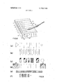
- a fundamental method of preparing magnetic tape with retrospective pulse modulated addresses utilizes a punched paper tape as shown in FIG. 7.
- a simple manual control punch may be used to set up a multiple of addresses in a punched paper tape, as for example, that shown in FIG. 7(a).
- start and reference punches and end of address block punches preferably will be placed in rows different from the address number punches as shown. This facilitates circuit arrangements for controlling the movement of the paper tape, as well as visual observation, and the recording of corresponding information magnetically on the magnetic tape.
- a label 250 shown in FIG. 8 on the near side of a rectangular object 252 of generally rectangular configuration can be scanned manually by a probe 254 containing an optical device for sensing the difference between the background and the marks on the label.
- a probe 254 containing an optical device for sensing the difference between the background and the marks on the label Such an arrangement would be extremely handy in a merchandising enterprise. Labels attached to each article for sale identify that article and initiate computer assisted operations in the merchandising organization for performing all the necessary calculations, printing a sale slip for the customer listing the date of purchase, a brief identity of the items, quantity of each, price each and extended together with a total price.
- inventory and sales records are generated and/or updated.
- the optical systems do not require synchronizing and/or speed control.
- the operator such as a checker, merely passes the tip of the probe 254 over the label in the direction indicated by the arrowhead 258 and across the bars 260. While uniform rate and direction of movement is recognized as desirable, variations normal in human endeavor will not affect the translation of the bar data to electric pulse data in accordance with retrospective pulse modulation on the label.
- An aspect of the invention that should not be overlooked is the freedom of transducing data several times without adding the errors.
- An example of a practical operation is the optical scanning of labels manually for recording the resulting data on a magnetic tape recorder of low speed regulation and later entering that data into a central computing system having an entirely different range of speed and much tighter regulation.
- each package preferably bears a label such as the label 250 and the sales clerk merely runs a probe 254 over the label.
- a simple keyboard may be used instead of the label.
- Such a simple keyboard is illustrated by the object 252 and the form shown at FIG. 9(b).
- Other configurations may be' used, such as dots of two colors interposed in the'transverse direction, if desired; with which it is not necessary to offset at all. Color filters in the probe will direct the light properly for producing the output pulse trains.
- Predetermined start and reference bar code combinations are contemplated for initializing the circuitry for operating on the particular color bar codes.
- a raster label manifested in light and dark line segments on a raster label may be a keyboard or checker identification number.
- a plurality of surfaces 270 have bar codes for letters and numbers, and if desired, special characters or symbols.
- the probe 254 is brought across the corresponding surface as though it were on a label. In the interest of compactness, the bars are reduced in height and theprobe 254 is drawn across the bars by guiding against ledges 280 at the crest of the saw-tooth crosssection of the keyboard device 252.
- expensive keyboard devices are obviated and no additional circuitry or components are needed to accommodate articles on which labels are difficult toplace or use.
- FIG. 9(a) shows a layout of a label such as previously described.
- the arrowhead is used to indicate the direction in which the scan should be made where there is manual control over the scanning. Scanning from the other end of the label will result in mutilated data or gibberish at the outset.
- circuitry for sensing whether the direction is normal or inverse and treating the data accordingly. Such an ar rangement does not necessarily complicate the apparatus unduly.
- the addition of a single bar to the label in the form of a start bit at the end is sufficient.
- the processor is arranged eventually to reverse the message. The extra bar is justified, however, where the item and the label may provide the opportunity to scan in an initial direction or in but one direction only whether forwards or backwards.
- Another solution to this problem encompasses dual coding in differential manner so that the scan is always made in the proper direction regardless of the direction of the item.
- bars of two different colors both contrasting well with the background, are contemplated.
- the bars of the different colors are offset slightly from each other in the Alternately different colors are contemplated for the interval or color different between manifestations in the form of transition marks.
- Two successive intervals of the same color denote a binary unit (I) and successive unlike colors a naught (0).
- Reversible coding is had with two more colors. Each pair of colors serves as marks for the other colors. This is one example of using the penultimate interval for the reference interval.
- the interval manifested can be considered frequency. Extending this principle to audio and radio frequency energy is well within the skill of the artisan.
- the bar coding described hereinbefore is readily tional programming procedures.
- the bar code is then read by a probe having a nose sufficiently large to be placed over the display segment containing the bar coding.
- a mechanical plunger closes an electric switch on being pressed against the face of the CRT in conventional fashion for indicating actuation and then causes a spring loaded mirror and/or a prism to scan the bar code beneath the nose of the probe or pressure is continued by the student.
- the switch is reopened and the scanning is completed.
- the probe must then be lifted from the CRT face before scanning again.
- Optical recognition bars of substantial width will provide pulses at the transitions between bar and background.
- the spacing between transitions forms the retrospective pulse code as shown in FIG. 9(e) where the same information is coded as in the two preceding lines.
- FIG. 9(e) A similar arrangement useful in magnetic record tracks is illustrated schematically in FIG. 9(e) where the transitions between alternate polarities recorded convey the information.
- labels may be separated from each other by large area bars 298 as shown in FIG. 9(d). Such an arrangement is useful in chaining data groups as 'willbe described hereinafter in more detail.
- a shorter label is had with an arrangement of dualwidth lines or blocks and dual width intervals as shown in FIG. 9(1) and this label is read with a detector sensing both types of transition.
- retrospective pulse modulation comprises start and reference pulses followed by a continuous string of pulses at two different intervals in a binary system of conveying intelligence.
- the data rate is as good as many of the prior an pulse trained modulation schemes but no better. It affords the important advantage of being selfclocking and is capable of working with synchronous and asynchronous systems with simple interfacing apparatus.
- characters comprising eight pulses or lines will cover the entire alphameric range with 28 additional combinations for special characters and control signals. It is contemplated that strings of such characters, each character having its own start and reference pulses, be transmitted and an electronic counter be used in the decoding process for each character. The counter is reset so that the pulse used for reset is used as the new start pulse for the next succeeding character. In this manner, only the space between the last bar of one group and the first bar of the next does not carry infonnation.
- One code set uses a narrow space as the reference space; one set uses a wide space as the reference space; and another set is the minimum length code set shown in the second column using either the narrow or the wide reference space to minimize code length.
- the fourth possible set comprises maximum length characters and therefore is the least attractive.
- An advantage of the code sets over the continuous coding is that chaining is not used; each stands alone and is not dependent upon its predecessor. Each can be put on a typewriter device and printed as a sequency of Binary Coded Decimal (BCD) characters. This means a more simplified printing device can be used,
- a checking feature is to construct the message string or print the label so that the space between character codes is at least twice as large as the widest last bit space in the code character as shown in Table ll below showing an example of a three digit number encoded.
- Line A is the decimal number 017 corresponding to the coding at line B while the binary data delivered to the data processing system is shown at line C. Discarded bits are shown at line D. This will always insure that there are two zeros between each character which are'ignored in sending data to the processor.
- Table III below shows characters whose codes can be free standing or can be chained.
- Each character code is to be the same length as that of any other character. This is accomplished by realizing that the wide spaces within different characters need not be exactly the same. For example, the wide space in character 2 is the normal spacing of twice that of the narrow space, but the wide space in character 3 has been selected so that the character code is the same overall length as all of the rest. Characters 3, 7, 9, l2, 14 all contain this extra wide space. Since character 15 has no wide space, the narrow spaces are equally expanded to fill the length. Because of the nature of the decoding circuitry, these variations in spacing within a string of characters are completely acceptable. The circuitry is arranged to detect spacings that are the same or different from the retrospective spacing on which the coding is based.
- the code set includes a startreference space for each character and therefore they may be printed as a series of free standing characters.
- the decoding circuitry uses the first four data bits and discards the fifth of each character.
- the fixed length code saves 14 percent in label length as well as 14 percent in data transmission time and computer handling time.
- Table V shows coded portions of the decimal numbers 0-9 for use with such a printing device for producing the shortest length label possible for binary-coded-decimal characters.
- the numbers only are given here in the interest of brevity; alphabetic and special characters are generated in the same fashion and the coding is applicable to both free characters and to chaining.
- the last code bar spacing of a character is used as a starting reference for the next character in the latter mode.
- a simple hand printing device comprises a plurality of type bands or wheels having all the characters desired in both forms shown in Table V on each band or wheel.
- the second column shows the bar code of each type bar for the numerals in the first column when the narrow spaced S-R bars (as shown at line are used to initiate a line of bars. Note the alignment of the bars in the column with respect to the# key.
- the fifth column shows the bar arrangement of the type bar (usually allotted to an upper case" character) for that number in the first column when a wide spacing is used for reference (that is, when the last interval of the preceding coded character is a wide interval).
- the wide spacing is indicated by the dotted lines (:2) to show the alignment but not even these dots appear on the type bar.
- the narrow start version is printed with the typewriter shift key down and the wide start elements are printed with the shift key up as indicated in the fourth and seventh columns.
- the typewriter is manually or automatically shifted up. This is accomplished automatically by adding a tab on the key bar of each print bar ending with a wide spacing. As the print bar returns from printing, the tab is arranged to trip the shift lever of an electric typewriter to shift the type segments to the shift up position.
- the escapement is proportional to the length of the coded type bar in this arrangement as evidenced by the numbers of units of escapement given in the third and sixth columns.
- One BCD notation useful here is the 7-4-2-1 base shown in the second column. This bit value combination will be recognized as being one used in 2 out of 5" protected coding.
- Table Vlll below shows an example of a chained" group of characters from the The code patterns described immediately hereinbefore are reproduceable in optically or magnetically recording media. Frequently one carrier can utilize both. For example, a credit card. a students registration card or the like can have optically. electrically. magnetically and mechanically readable data, the latter being embossed in the manner of conventional credit cards.
- the reading apparatus need only have a slotted guideway in which the card is drawn by the holder. Optical, magnetic, electric and mechanical sensing apparatus is positioned internally along the guideway.
- the magnetic sensors commercially available are entirely suitable where a guide is available for insuring appropriate orientation and means are present for insuring appropriate speed since the conventional inexperienced magnetic recording and reproducing transducers have a more limited range of speed and orientation than the other three types of sensors.
- Speed is readily controlled by a simple resistor-capacitor timing circuit controlling an electric lock on a gate or an electric switch arrangement actuating an indicator acknowledging proper speed and also entry to the associated data processing system.
- Retrospective pulse modulation encoding and decoding apparatus comprising,
- a pulse train generating circuit for producing substantially uniformly spaced pulses at the output terminals thereof
- said modulating circuit being arranged for selectively varying the spacing of said pulses from said generating circuit as applied at said modulating circuit input terminals in response to the data applied at said data input terminals for delivering pulses spaced apart at said modulating circuit output terminals by a plurality of differing intervals with data of one nature represented by a plurality of pulses spaced apart by successive, equal intervals and data of another nature represented by a plurality of pulses spaced apart by successive, unequal intervals,
- measuring circuitry responsive to pulses emanating from the output terminals of said modulating circuit and having logical circuitry for measuring successive intervals between said emanating pulses
- comparing circuitry coupled to said measuring circuitry for comparing successive pairs of intervals with each interval after the first interval being compared with the preceding and thereafter the succeeding interval
- circuitry coupled to said comparing circuitry for interpreting equal pairsof intervals as information of one nature and unequal pairs of intervals as information of another nature.
- Retrospective pulse modulation encoding and decoding apparatus as defined in claim 1 and incorporating rate determining circuitry coupled to said comparing circuitry for producing an output indicative of the efficacy of the translation of pulses from said comparing circuitry, and
- controlling circuitry coupled between rate determining circuitry and said generating circuit for varying the recurrence rate of said generating circuit in response to the output of said rate determining circuitry.
- Retrospective pulse modulation encoding and decoding apparatus as defined in claim 2 and wherein said rate determining and controlling circuitry are arranged for maximum recurrence rate in the absence of output from said rate determining circuitry and for reducing the recurrence rate as that output increases.
- a retrospective pulse modulation communication system comprising,
- a pulse train generating circuit for producing electric pulses spaced apart in time at output terminals, and arranged for control of the spacing of said pulses by a control potential at control terminals of said generating circuit
- a rate controlling circuit connected to said generating circuit for producing said control potential in response to a control signal applied at control terminals of said controlling circuit
- modulating circuitry having two input circuits and an output circuit
- said modulating circuitry being arranged for altering the spacing of said pulses by a plurality of intervals with each interval after the first interval associated with a preceding interval for representing elements of said characters in accordance with the information in said signal demodulating circuitry having an input circuit arranged for responding to said output circuit of said modulating circuitry and an output circuit,
- said demodulating circuitry responding to the spacing of said pulses by measuring successive intervals therebetween and comparing successive pairs of intervals with each interval after the first interval being compared with the preceding and thereafter the succeeding interval except for the last interval,
- error detecting circuitry coupled to said demodulating circuitry, and circuitry coupled between said error detecting circuitry and said generating circuit for varying the rate of generation of said pulses inversely to the rate of errors detected by said error detecting circuitry.
- Retrospective pulse modulation encoding and decoding apparatus comprising,
- an advancement device coupled to said elements for positioning said recording element relative to said retaining element successively in a given direction in substantially uniform intervals
- circuitry coupled to said scanning element for measuring successive intervals of said wave and comparing successive pairs of said intervals with each interval after the first interval being compared with the preceding interval and with the succeeding interval except for the last interval for substantially equal and substantially unequal intervals on each comparison thereby for reproducing said data.
- Retrospective pulse modulation encoding and decoding apparatus as defined in claim and wherein said mechanism includes means for initiating the recording by a pair of manifestations spaced apart by one of said intervals.
- Retrospective pulse modulation encoding and decoding apparatus as defined in claim 6 and wherein said initiating means are active before each character of information.
- Retrospective pulse modulation encoding and decoding apparatus as defined in claim 6 and wherein said initiating means are active for manifesting said pair of manifestations at one of at least two differing intervals.
- Retrospective pulse modulation encoding and decoding apparatus as defined in claim 6 and incorporating means for separating each' character from the preceding and the succeeding characters in the se- 10.
- Retrospective pulse modulation encoding and decoding apparatus as defined in claim 9 and wherein said separating means are active over an interval differing from either of said two intervals.
- Retrospective pulse modulation encoding and decoding apparatus as defined in claim 6 and wherein said initiating means are active for overlapping the final manifestation of any previous character.
- Retrospective pulse modulation encoding and decoding apparatus as defined in claim 6 and wherein said initiating means are active for overlapping the final two manifestations of any previous character.
- Retrospective pulse modulation encoding and decoding apparatus as defined in claim 5 and wherein said mechanism is active for manifesting characters of a minimum overall intervals.
- Retrospective pulse modulation encoding and decoding apparatus as defined in claim 13 and wherein said mechanism is active for manifesting characters of a uniform overall interval.
- Retrospective pulse modulation encoding and decoding apparatus as defined in claim 5 and wherein said recording apparatus is a printer for recording said data on a paper document in the form of printed bars arranged parallel to each other and spaced apart in said given direction, and said scanning element is an optical scanner with a photoelectric device for producing said electric wave.
- said recording apparatus is a printer for recording said data in the form of bars of a plurality of widths, and said scanning element producers said electric wave in response to the sensing of both edges of said bars. 17.
- Retrospective pulse modulation encoding and decoding apparatus as defined in claim 15 and wherein said recording apparatus is a magnetic transducer for recording said data on a magnetic record document in the form of transitions of a plurality of magnetic domains and said scanning element is an electromagnetic transducer.
- said recording apparatus is a magnetic transducer for recording said data on a magnetic record document in the form of transitions of a plurality of magnetic domains and said scanning element is an electromagnetic transducer.
- Retrospective pulse modulation encoding and decoding apparatus as defined in claim 5 and wherein said recording apparatus is a punch for recording said data in the form of apertures spaced apart in said document, and f said scanning element includes electric contact devices for producing said electric wave.
- said recording apparatus is a punch for recording said in the form of apertures spaced apart in said document, and said scanning element includes a photosensitive device for producing said electric wave.
- said scanning element is arranged for movement over said document at a speed independent of the rate of recording of information on said document for producing said electric wave.
Landscapes
- Engineering & Computer Science (AREA)
- Theoretical Computer Science (AREA)
- Physics & Mathematics (AREA)
- Signal Processing (AREA)
- General Engineering & Computer Science (AREA)
- General Physics & Mathematics (AREA)
- Human Computer Interaction (AREA)
- Artificial Intelligence (AREA)
- Computer Vision & Pattern Recognition (AREA)
- Spectroscopy & Molecular Physics (AREA)
- Computer Networks & Wireless Communication (AREA)
- Signal Processing For Digital Recording And Reproducing (AREA)
- Dc Digital Transmission (AREA)
- Compression, Expansion, Code Conversion, And Decoders (AREA)
Applications Claiming Priority (1)
| Application Number | Priority Date | Filing Date | Title |
|---|---|---|---|
| US3195970A | 1970-04-27 | 1970-04-27 |
Publications (1)
| Publication Number | Publication Date |
|---|---|
| US3708748A true US3708748A (en) | 1973-01-02 |
Family
ID=21862326
Family Applications (1)
| Application Number | Title | Priority Date | Filing Date |
|---|---|---|---|
| US00031959A Expired - Lifetime US3708748A (en) | 1970-04-27 | 1970-04-27 | Retrospective pulse modulation and apparatus therefor |
Country Status (13)
| Country | Link |
|---|---|
| US (1) | US3708748A (de) |
| JP (2) | JPS5037081B1 (de) |
| BE (1) | BE766359A (de) |
| CA (2) | CA958487A (de) |
| CH (1) | CH528183A (de) |
| DE (1) | DE2120096B2 (de) |
| DK (1) | DK135438C (de) |
| ES (1) | ES390388A1 (de) |
| FR (1) | FR2092464A5 (de) |
| GB (1) | GB1324223A (de) |
| NL (1) | NL7103604A (de) |
| NO (1) | NO136631C (de) |
| SE (1) | SE369014B (de) |
Cited By (13)
| Publication number | Priority date | Publication date | Assignee | Title |
|---|---|---|---|---|
| US3755654A (en) * | 1972-07-31 | 1973-08-28 | Ibm | Digital decoding of retrospective pulse modulation |
| US3763351A (en) * | 1972-07-14 | 1973-10-02 | Ibm | Bar code scanner |
| US3849632A (en) * | 1972-06-19 | 1974-11-19 | Pitney Bowes Inc | Reading apparatus for optical bar codes |
| DE2421389A1 (de) * | 1973-06-22 | 1975-01-23 | Ibm | Schaltungsanordnung zum ableiten von datenimpulsen aus stoerungsbehafteten eingangssignalen |
| US3932731A (en) * | 1974-08-02 | 1976-01-13 | Bell Telephone Laboratories, Incorporated | Code converter |
| US3988729A (en) * | 1975-01-29 | 1976-10-26 | The United States Of America As Represented By The Administrator Of The National Aeronautics And Space Administration | Differential pulse code modulation |
| US4012716A (en) * | 1971-11-16 | 1977-03-15 | Monarch Marking Systems, Inc. | Coded record and method of and system for interpreting the record |
| DE2645460A1 (de) * | 1975-10-29 | 1977-05-12 | Ibm | Verfahren und vorrichtung zum auswerten von selbsttaktierend codierten signalen |
| US4264934A (en) * | 1979-04-23 | 1981-04-28 | Bell Telephone Laboratories, Incorporated | Rate adaptive writer for a card having a magnetizable surface |
| US4519054A (en) * | 1982-06-03 | 1985-05-21 | News Log International, Inc. | Method for formatting optically encoded digital data on a substrate and the data record carrier formed thereby |
| DE19927318A1 (de) * | 1999-06-15 | 2000-12-21 | Mannesmann Vdo Ag | Verfahren zur drahtlosen Übertragung von Daten |
| US6380965B1 (en) * | 1994-10-14 | 2002-04-30 | Esselte N.V. | Tape printing apparatus |
| GB2411800A (en) * | 2004-03-04 | 2005-09-07 | Philip John Connor | Spread spectrum communication system using impulse modulation |
Families Citing this family (6)
| Publication number | Priority date | Publication date | Assignee | Title |
|---|---|---|---|---|
| IT992697B (it) * | 1972-09-07 | 1975-09-30 | Ibm | Circuito demudulatore perfezionato |
| US4027267A (en) * | 1976-06-01 | 1977-05-31 | International Business Machines Corporation | Method of decoding data content of F2F and phase shift encoded data streams |
| JPS60180461U (ja) * | 1984-05-10 | 1985-11-30 | セノ−株式会社 | 腹背筋トレ−ニングマシン |
| DE3639252C1 (en) * | 1986-11-17 | 1991-05-02 | Honeywell Regelsysteme Gmbh | Transmitting pulsed digital signals immune to interference - spacing at intervals to represent 1 and 0 and recovering at receiver by resettable time window |
| DE3640003C2 (de) * | 1986-11-22 | 1996-07-25 | Schunk Produktionsgesellschaft | Verfahren und Vorrichtung zur Informationsübertragung, insbesondere für mobile Informationsträgersysteme |
| US11987930B2 (en) | 2019-11-26 | 2024-05-21 | Kornit Digital Ltd. | Method for printing on colored synthetic fabrics utilizing a dye discharge material |
Citations (4)
| Publication number | Priority date | Publication date | Assignee | Title |
|---|---|---|---|---|
| US3427444A (en) * | 1965-02-15 | 1969-02-11 | Ibm | Coding circuits for data transmission systems |
| US3510780A (en) * | 1966-09-12 | 1970-05-05 | Motorola Inc | Two-state communication devices having combined clock and information signals |
| US3524926A (en) * | 1966-06-15 | 1970-08-18 | Xerox Corp | System for delta encoding at selected intervals |
| US3597752A (en) * | 1969-09-17 | 1971-08-03 | Burroughs Corp | Fm magnetic recording and sensing utilizing bit periods of different lengths |
-
1970
- 1970-04-27 US US00031959A patent/US3708748A/en not_active Expired - Lifetime
-
1971
- 1971-03-11 FR FR7110266A patent/FR2092464A5/fr not_active Expired
- 1971-03-18 NL NL7103604A patent/NL7103604A/xx unknown
- 1971-03-25 JP JP46016953A patent/JPS5037081B1/ja active Pending
- 1971-04-15 CA CA110,403A patent/CA958487A/en not_active Expired
- 1971-04-19 GB GB997971*[A patent/GB1324223A/en not_active Expired
- 1971-04-20 ES ES390388A patent/ES390388A1/es not_active Expired
- 1971-04-22 CH CH586971A patent/CH528183A/de not_active IP Right Cessation
- 1971-04-24 DE DE19712120096 patent/DE2120096B2/de not_active Withdrawn
- 1971-04-26 SE SE05399/71A patent/SE369014B/xx unknown
- 1971-04-26 NO NO1549/71A patent/NO136631C/no unknown
- 1971-04-26 DK DK199971A patent/DK135438C/da active
- 1971-04-27 BE BE766359A patent/BE766359A/xx unknown
-
1976
- 1976-09-07 JP JP51106360A patent/JPS5267222A/ja active Granted
-
1977
- 1977-08-18 CA CA285,173A patent/CA1037607A/en not_active Expired
Patent Citations (4)
| Publication number | Priority date | Publication date | Assignee | Title |
|---|---|---|---|---|
| US3427444A (en) * | 1965-02-15 | 1969-02-11 | Ibm | Coding circuits for data transmission systems |
| US3524926A (en) * | 1966-06-15 | 1970-08-18 | Xerox Corp | System for delta encoding at selected intervals |
| US3510780A (en) * | 1966-09-12 | 1970-05-05 | Motorola Inc | Two-state communication devices having combined clock and information signals |
| US3597752A (en) * | 1969-09-17 | 1971-08-03 | Burroughs Corp | Fm magnetic recording and sensing utilizing bit periods of different lengths |
Cited By (14)
| Publication number | Priority date | Publication date | Assignee | Title |
|---|---|---|---|---|
| US4012716A (en) * | 1971-11-16 | 1977-03-15 | Monarch Marking Systems, Inc. | Coded record and method of and system for interpreting the record |
| US3849632A (en) * | 1972-06-19 | 1974-11-19 | Pitney Bowes Inc | Reading apparatus for optical bar codes |
| US3763351A (en) * | 1972-07-14 | 1973-10-02 | Ibm | Bar code scanner |
| US3755654A (en) * | 1972-07-31 | 1973-08-28 | Ibm | Digital decoding of retrospective pulse modulation |
| DE2421389A1 (de) * | 1973-06-22 | 1975-01-23 | Ibm | Schaltungsanordnung zum ableiten von datenimpulsen aus stoerungsbehafteten eingangssignalen |
| US3932731A (en) * | 1974-08-02 | 1976-01-13 | Bell Telephone Laboratories, Incorporated | Code converter |
| US3988729A (en) * | 1975-01-29 | 1976-10-26 | The United States Of America As Represented By The Administrator Of The National Aeronautics And Space Administration | Differential pulse code modulation |
| DE2645460A1 (de) * | 1975-10-29 | 1977-05-12 | Ibm | Verfahren und vorrichtung zum auswerten von selbsttaktierend codierten signalen |
| US4264934A (en) * | 1979-04-23 | 1981-04-28 | Bell Telephone Laboratories, Incorporated | Rate adaptive writer for a card having a magnetizable surface |
| US4519054A (en) * | 1982-06-03 | 1985-05-21 | News Log International, Inc. | Method for formatting optically encoded digital data on a substrate and the data record carrier formed thereby |
| US6380965B1 (en) * | 1994-10-14 | 2002-04-30 | Esselte N.V. | Tape printing apparatus |
| DE19927318A1 (de) * | 1999-06-15 | 2000-12-21 | Mannesmann Vdo Ag | Verfahren zur drahtlosen Übertragung von Daten |
| GB2411800A (en) * | 2004-03-04 | 2005-09-07 | Philip John Connor | Spread spectrum communication system using impulse modulation |
| GB2411800B (en) * | 2004-03-04 | 2006-12-06 | Philip John Connor | Spread spectrum communication system |
Also Published As
| Publication number | Publication date |
|---|---|
| DK135438C (da) | 1977-10-10 |
| JPS5267222A (en) | 1977-06-03 |
| JPS5037081B1 (de) | 1975-11-29 |
| SE369014B (de) | 1974-07-29 |
| FR2092464A5 (de) | 1972-01-21 |
| GB1324223A (en) | 1973-07-25 |
| JPS5616462B2 (de) | 1981-04-16 |
| DK135438B (da) | 1977-04-25 |
| DE2120096B2 (de) | 1972-09-28 |
| CH528183A (de) | 1972-09-15 |
| NO136631B (de) | 1977-06-27 |
| CA1037607A (en) | 1978-08-29 |
| ES390388A1 (es) | 1974-06-01 |
| CA958487A (en) | 1974-11-26 |
| NO136631C (no) | 1977-10-05 |
| DE2120096A1 (de) | 1971-11-11 |
| NL7103604A (de) | 1971-10-29 |
| BE766359A (fr) | 1971-09-16 |
Similar Documents
| Publication | Publication Date | Title |
|---|---|---|
| US3708748A (en) | Retrospective pulse modulation and apparatus therefor | |
| US3882301A (en) | Retrospective pulse modulation including bar coding and apparatus therefor | |
| US2791310A (en) | Character printing and encoding apparatus | |
| US2952008A (en) | Record actuated timing and checking means | |
| US3000000A (en) | Automatic reading system | |
| US4059224A (en) | Code recognition record medium and technique | |
| US3281806A (en) | Pulse width modulation representation of paired binary digits | |
| US4356473A (en) | Monetary document profile location and predetermined selected path apparatus | |
| US2811102A (en) | Random printing means | |
| US3626160A (en) | Magnetic record sensing device | |
| US3108254A (en) | Machine reading of handwritten characters | |
| US4012716A (en) | Coded record and method of and system for interpreting the record | |
| US3809863A (en) | Article coding system | |
| US3701886A (en) | Method of representing data codes with equal width bar and device for reading same | |
| US3737632A (en) | Rate adaptive nonsynchronous demodulator apparatus for biphase binary signals | |
| US2856256A (en) | Coded magnetic binary recorders | |
| US4259569A (en) | Code sensing system | |
| US3283303A (en) | Synchronized and coded character recognition system | |
| US3602697A (en) | Card-reading system | |
| US3359405A (en) | Data record and sensing means therefor | |
| GB1519256A (en) | Code discriminator | |
| US2807664A (en) | Information translating system | |
| US3805175A (en) | Retrospective pulse modulation decoding method and apparatus | |
| US3391387A (en) | Character recognition system | |
| US3559170A (en) | Methods and apparatus for data input to a computer |