US3663841A - Ultrasonic transducers - Google Patents
Ultrasonic transducers Download PDFInfo
- Publication number
- US3663841A US3663841A US30702A US3663841DA US3663841A US 3663841 A US3663841 A US 3663841A US 30702 A US30702 A US 30702A US 3663841D A US3663841D A US 3663841DA US 3663841 A US3663841 A US 3663841A
- Authority
- US
- United States
- Prior art keywords
- radiating
- radiating member
- piezoelectric element
- transducer
- unitary
- Prior art date
- Legal status (The legal status is an assumption and is not a legal conclusion. Google has not performed a legal analysis and makes no representation as to the accuracy of the status listed.)
- Expired - Lifetime
Links
- 239000006096 absorbing agent Substances 0.000 claims description 5
- 239000013078 crystal Substances 0.000 abstract description 3
- 101150038956 cup-4 gene Proteins 0.000 description 11
- 241000283984 Rodentia Species 0.000 description 5
- 230000005855 radiation Effects 0.000 description 5
- 239000000463 material Substances 0.000 description 4
- 230000008878 coupling Effects 0.000 description 3
- 238000010168 coupling process Methods 0.000 description 3
- 238000005859 coupling reaction Methods 0.000 description 3
- 239000004033 plastic Substances 0.000 description 3
- 229920003023 plastic Polymers 0.000 description 3
- 230000001846 repelling effect Effects 0.000 description 3
- 230000035945 sensitivity Effects 0.000 description 3
- 241001465754 Metazoa Species 0.000 description 2
- JRPBQTZRNDNNOP-UHFFFAOYSA-N barium titanate Chemical compound [Ba+2].[Ba+2].[O-][Ti]([O-])([O-])[O-] JRPBQTZRNDNNOP-UHFFFAOYSA-N 0.000 description 2
- 238000004880 explosion Methods 0.000 description 2
- 241000282414 Homo sapiens Species 0.000 description 1
- 239000004793 Polystyrene Substances 0.000 description 1
- 241000607479 Yersinia pestis Species 0.000 description 1
- 229910002113 barium titanate Inorganic materials 0.000 description 1
- 239000000919 ceramic Substances 0.000 description 1
- 230000000295 complement effect Effects 0.000 description 1
- 238000013016 damping Methods 0.000 description 1
- 238000006073 displacement reaction Methods 0.000 description 1
- 230000000694 effects Effects 0.000 description 1
- 230000003993 interaction Effects 0.000 description 1
- 238000012986 modification Methods 0.000 description 1
- 230000004048 modification Effects 0.000 description 1
- 229920002223 polystyrene Polymers 0.000 description 1
- 239000000843 powder Substances 0.000 description 1
- 230000000750 progressive effect Effects 0.000 description 1
Images

Classifications
-
- B—PERFORMING OPERATIONS; TRANSPORTING
- B06—GENERATING OR TRANSMITTING MECHANICAL VIBRATIONS IN GENERAL
- B06B—METHODS OR APPARATUS FOR GENERATING OR TRANSMITTING MECHANICAL VIBRATIONS OF INFRASONIC, SONIC, OR ULTRASONIC FREQUENCY, e.g. FOR PERFORMING MECHANICAL WORK IN GENERAL
- B06B1/00—Methods or apparatus for generating mechanical vibrations of infrasonic, sonic, or ultrasonic frequency
- B06B1/02—Methods or apparatus for generating mechanical vibrations of infrasonic, sonic, or ultrasonic frequency making use of electrical energy
- B06B1/06—Methods or apparatus for generating mechanical vibrations of infrasonic, sonic, or ultrasonic frequency making use of electrical energy operating with piezoelectric effect or with electrostriction
- B06B1/0644—Methods or apparatus for generating mechanical vibrations of infrasonic, sonic, or ultrasonic frequency making use of electrical energy operating with piezoelectric effect or with electrostriction using a single piezoelectric element
- B06B1/0655—Methods or apparatus for generating mechanical vibrations of infrasonic, sonic, or ultrasonic frequency making use of electrical energy operating with piezoelectric effect or with electrostriction using a single piezoelectric element of cylindrical shape
Definitions
- ABSTRACT An ultrasonic transducer which includes a piezo-electric element of annular form having electrodes provided upon its inner and outer curved surfaces to permit the crystal to be vibrated in the circumferential mode, wherein a radiating member in the form of a cup or tube closed at one end is fitted to the annulus, support means being attached to the bottom of the cup or tube.
- This invention relates to ultrasonic transducers, and more particularly to such transducers capable of radiating ultrasonic power at a relatively high level (above watts r.m.s) for use, for example, for rodent repelling purposes.
- the ultrasonic signal should be radiated at a frequency which does not affect human beings and other animals it is not desired to disturb. Further, the frequency of the radiated signal must fall within the critical range of maximum sensitivity of the animal to be repelled.
- the transducer should be capable of being designed to operate in explosion hazard areas and have a very low failure rate. In addition it is desirable that the transducer should radiate the ultrasonic signals in as broad a field as possible and with the maximum power.
- I-lom type dynamic loud speakers have been employed to convert the electrical signals generated for pest control into ultrasonic waves. These devices have a number of limitations and problems associated with their use for this purpose.
- a tweeter is designed to operate from about 5 kc/s up to a maximum of 20 kc/s. Because the critical sensitivity of the rodent to be repelled lies between 20 and 50 kc/s the tweeter is operated beyond its upper limit with a consequent large reduction in power.
- Dynamic speakers of whatever type have a resonant frequency much below that of the desired ultrasonic frequency and therefore considerable power is required to drive the diaphragm and this introduces unacceptable losses.
- the present invention consists in an ultrasonic transducer which includes a piezo-electric element of annular form having electrodes provided upon its inner and outer curved surfaces to permit the crystal to be vibrated in the circumferential mode, wherein a radiating member in the form of a cup or tube closed at one end is fitted to the annulus, support means being attached to the bottom of the cup or tube.
- FIG. 1 is a longitudinal section through an ultrasonic transducer according to the present invention.
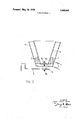
- FIGS. 2 and 3 show two modifications to FIG. 1.
- FIG. 1 shows an ultrasonic transducer arranged to convert electrical signals into radiated ultrasonic energy in the region of one fixed frequency for the purpose of repelling rodents.
- the transducer includes a piezo-electric ceramic ring 1 formed from Barium Titanate, Lead Zirconate or other polarized polycrystalline material having silvered surfaces 2 and which can be caused, when energized by a suitable electrical generator via leads 3, to vibrate in the circumferential mode.
- a piezo-electric ceramic ring 1 formed from Barium Titanate, Lead Zirconate or other polarized polycrystalline material having silvered surfaces 2 and which can be caused, when energized by a suitable electrical generator via leads 3, to vibrate in the circumferential mode.
- a radiating member in the fonn of a tapered cup or tube 4 closed at one end and dimensioned to resonate at a common frequency with the ring 1, which frequency is made to coincide with the sharply critical threshold of the rodents sensitivity.
- the whole assembly is impedance matched into air and eliminates the need for a conventional diaphragm.
- the cup 4 is mounted on a bracket 5 with the aid of a bolt 6 and resilient washer 7 at or adjacent to the geometrical center of the base of the cup 4, the best position preferably being ascertained by finding the node with the aid of a powder.
- the ring 1 is in direct contact with the cup 4 for the radiation of ultrasonic energy with the greatest efficiency, the whole assembly being supported in such a manner as to allow maximum vibration in the desired mode.
- the cup behaves as a resonant element and is dimensioned so as to amplify the vibrations of the ring and increase the area of radiation. Since the mode of vibration is circumferential, the transducer exhibits the multi-path radiation characteristics required for general radiation coverage of an area.
- the cup 4 is preferably made an interference fit within the ring 1. It is composed of a therrnosetting plastics material, and the density of the material, the thickness of the walls and the overall length of the cup are chosen to provide resonance at the desired frequency, the final tuning being effected by grinding the periphery at the open end of the cup 4 to achieve maximum displacement, i.e., an antinode.
- Allowance is made for the efiect of the mass of air acting upon the cup by dimensioning the ring to resonate, by itself, at a frequency say 5 percent higher than the final desired frequency.
- a Barium Titanate ring of outside diameter 2.8 inches, inside diameter 2.3 inches and length 1 inch resonated at 23 kc/s. Attached to a cup, the overall effective frequency fell to 21.98 kc/s.
- two cups may be secured together coaxially on a common support to face in opposite directions, two rings being provided to fonn a twin unit.
- a plastic plate 8 is provided to bear upon ring 1 rear face, pressure being exerted by bolt 6 and associated washer through cup 4 base.
- Mechanical coupling of ring 1 to cup 4 is then progressive via the resilient washer 7 which is mounted between bracket 5 and end plate 8.
- the acoustic efficiency is increased by fitting the ring 1 into a further tapered cup 9 positioned co-axially with the cup 4, thereby adding to the total vibrating area since the ring 1 is in contact with both cups 4 and 9.
- the outer cup 9 is dimensioned so that at resonance it is complementary to the inner cup 4 (i.e., no standing waves are formed) and both cups are molded from a polystyrene plastic material chosen to suit the operating parameter imposed.
- the spacing between the two cups 4 and 9 is such as to avoid acoustic interaction.
- a vibration absorber 8 having threaded studs 8a and 8b has a natural frequency of 1,500 c/s and is secured to nodal points on the cups 4 and 9 thereby presenting a negligible load.
- the absorber 8 serves to couple the bottoms of both cups 4 and 9, with the ring 1 trapped between the two cups 4 and 9, and to couple all these components to the brackets 5.
- a transducer for radiating ultrasonic power when energized by an electrical signal of ultrasonic frequency comprising, in combination:
- a radiating member having the shape of a truncated cone with a continuous conical portion closed at one end thereof by a flat 'portion unitary and integral with said conical portion and open at the other end thereof with a free unsupported periphery;
- said annular piezoelectric element being in direct contact with said continuous conical portion of said radiating member between said unitary integral flat portion and said free unsupported periphery in an annular line of contact whereby said radiating member may be caused to resonate at said ultrasonic frequency with said unsupported periphery positioned at an antinode;
- said annular line of contact being disposed in a plane substantially parallel to a plane containing said unitary integral flat portion of said radiating member;
- a transducer for radiating ultrasonic power in accordance with claim 1, wherein said radiating member is in an interference fit in said piezoelectric element.
Landscapes
- Engineering & Computer Science (AREA)
- Mechanical Engineering (AREA)
- Transducers For Ultrasonic Waves (AREA)
Abstract
An ultrasonic transducer which includes a piezo-electric element of annular form having electrodes provided upon its inner and outer curved surfaces to permit the crystal to be vibrated in the circumferential mode, wherein a radiating member in the form of a cup or tube closed at one end is fitted to the annulus, support means being attached to the bottom of the cup or tube.
Description
UnlIeG Stat X 5 1 JFK Parker ULTRASONIC TRANSDUCERS Joseph Donald Parker, London, England Electro-Mechanieal Design Limited, London, England Filed: Apr. 22, 1970 Appl. No.: 30,702
Inventor:
Assignee:
US. Cl. ..3l0/8.2, 179/110 A, 310/83, 310/94, 31 /96 Int. Cl. ..H01v7/00 Field ofSearch ..3 l0/8.8, 8.7, 8.4, 8.3, 8.2, 310/81, 9.6, 9.1, 9.5; 340/10; 179/110 References Cited UNITED STATES PATENTS Ballantine... ens/110A Harris ...310/8.4 X Nicolson ..179/1 10 [is] 3,663,841 1 May 16,1972
2,561,084 7/1951 Wickham et al I 79/1 10 2,005,741 6/1935 Hayes ....179/l10 3,302,163 l/1967 Andrews ..340/1O FOREIGN PATENTS OR APPLICATIONS 1,175,947 1/1970 Great Britain Primary Examiner-J. D. Miller Assistant Examiner-B. A. Reynolds Attorneylrving M. Weiner [57] ABSTRACT An ultrasonic transducer which includes a piezo-electric element of annular form having electrodes provided upon its inner and outer curved surfaces to permit the crystal to be vibrated in the circumferential mode, wherein a radiating member in the form of a cup or tube closed at one end is fitted to the annulus, support means being attached to the bottom of the cup or tube.
5 Claims, 3 Drawing Figures aten ted May 16, 1912 2 Sheets-Sheet 2 INVENTOR JosaPH DON/1L0 PHRKER ATTORNEY FIG. 3.
ULTRASONIC TRANSDUCERS This invention relates to ultrasonic transducers, and more particularly to such transducers capable of radiating ultrasonic power at a relatively high level (above watts r.m.s) for use, for example, for rodent repelling purposes.
It is an essential feature of certain rodent repelling devices that the ultrasonic signal should be radiated at a frequency which does not affect human beings and other animals it is not desired to disturb. Further, the frequency of the radiated signal must fall within the critical range of maximum sensitivity of the animal to be repelled. The transducer should be capable of being designed to operate in explosion hazard areas and have a very low failure rate. In addition it is desirable that the transducer should radiate the ultrasonic signals in as broad a field as possible and with the maximum power.
I-lom type dynamic loud speakers (Tweeters) have been employed to convert the electrical signals generated for pest control into ultrasonic waves. These devices have a number of limitations and problems associated with their use for this purpose. Primarily a tweeter is designed to operate from about 5 kc/s up to a maximum of 20 kc/s. Because the critical sensitivity of the rodent to be repelled lies between 20 and 50 kc/s the tweeter is operated beyond its upper limit with a consequent large reduction in power. Dynamic speakers of whatever type have a resonant frequency much below that of the desired ultrasonic frequency and therefore considerable power is required to drive the diaphragm and this introduces unacceptable losses. Because of the small diaphragm diameter and associated horn, at high frequencies the angle of radiation is narrow and sharply directional necessitating a number of speakers to cover a given area. Dynamic speakers used for this purpose are inherently unreliable when operated above 20 kc/s and the presence of a current carrying voice coil which dissipates heat can make the speaker unsuitable in certain explosion hazard areas.
The present invention consists in an ultrasonic transducer which includes a piezo-electric element of annular form having electrodes provided upon its inner and outer curved surfaces to permit the crystal to be vibrated in the circumferential mode, wherein a radiating member in the form of a cup or tube closed at one end is fitted to the annulus, support means being attached to the bottom of the cup or tube.
IN THE ACCOMPANYING DRAWINGS FIG. 1 is a longitudinal section through an ultrasonic transducer according to the present invention, and
FIGS. 2 and 3 show two modifications to FIG. 1.
In carrying the invention into effect according to one convenient mode by way of example, FIG. 1 shows an ultrasonic transducer arranged to convert electrical signals into radiated ultrasonic energy in the region of one fixed frequency for the purpose of repelling rodents.
The transducer includes a piezo-electric ceramic ring 1 formed from Barium Titanate, Lead Zirconate or other polarized polycrystalline material having silvered surfaces 2 and which can be caused, when energized by a suitable electrical generator via leads 3, to vibrate in the circumferential mode.
Within the ring 1 there is fitted a radiating member in the fonn of a tapered cup or tube 4 closed at one end and dimensioned to resonate at a common frequency with the ring 1, which frequency is made to coincide with the sharply critical threshold of the rodents sensitivity. The whole assembly is impedance matched into air and eliminates the need for a conventional diaphragm.
To facilitate mounting the device without damping and to increase the acoustic coupling, the cup 4 is mounted on a bracket 5 with the aid of a bolt 6 and resilient washer 7 at or adjacent to the geometrical center of the base of the cup 4, the best position preferably being ascertained by finding the node with the aid of a powder.
In this way, the ring 1 is in direct contact with the cup 4 for the radiation of ultrasonic energy with the greatest efficiency, the whole assembly being supported in such a manner as to allow maximum vibration in the desired mode. The cup behaves as a resonant element and is dimensioned so as to amplify the vibrations of the ring and increase the area of radiation. Since the mode of vibration is circumferential, the transducer exhibits the multi-path radiation characteristics required for general radiation coverage of an area.
The cup 4 is preferably made an interference fit within the ring 1. It is composed of a therrnosetting plastics material, and the density of the material, the thickness of the walls and the overall length of the cup are chosen to provide resonance at the desired frequency, the final tuning being effected by grinding the periphery at the open end of the cup 4 to achieve maximum displacement, i.e., an antinode.
Allowance is made for the efiect of the mass of air acting upon the cup by dimensioning the ring to resonate, by itself, at a frequency say 5 percent higher than the final desired frequency. In a particular example, a Barium Titanate ring of outside diameter 2.8 inches, inside diameter 2.3 inches and length 1 inch resonated at 23 kc/s. Attached to a cup, the overall effective frequency fell to 21.98 kc/s.
If desired two cups may be secured together coaxially on a common support to face in opposite directions, two rings being provided to fonn a twin unit.
In an alternative arrangement shown in FIG. 2 a plastic plate 8 is provided to bear upon ring 1 rear face, pressure being exerted by bolt 6 and associated washer through cup 4 base. Mechanical coupling of ring 1 to cup 4 is then progressive via the resilient washer 7 which is mounted between bracket 5 and end plate 8. By effectively restricting vibration of ring 1 in the longitudinal mode, the amplitude of vibration in the unrestricted mode, i.e., circumferential direction is increased. Moreover thering l and cup 4 are positively located with respect to each other. 1
In a further. alternative arrangement shown in FIG. 3, the acoustic efficiency is increased by fitting the ring 1 into a further tapered cup 9 positioned co-axially with the cup 4, thereby adding to the total vibrating area since the ring 1 is in contact with both cups 4 and 9.
The outer cup 9 is dimensioned so that at resonance it is complementary to the inner cup 4 (i.e., no standing waves are formed) and both cups are molded from a polystyrene plastic material chosen to suit the operating parameter imposed. The spacing between the two cups 4 and 9 is such as to avoid acoustic interaction.
A vibration absorber 8 having threaded studs 8a and 8b has a natural frequency of 1,500 c/s and is secured to nodal points on the cups 4 and 9 thereby presenting a negligible load. The absorber 8 serves to couple the bottoms of both cups 4 and 9, with the ring 1 trapped between the two cups 4 and 9, and to couple all these components to the brackets 5. As a nut 10 is tightened on stud 8a, it progressively increases the mechanical coupling between ring 1 and the two cups 4 and 9 so that a certain degree of amplitude tuning adjustment can be obtained in this way.
In certain circumstances, it may be desirable to eliminate the inner cup 4, suitable means being provided for bracing the ring 1 against the absorber 8.
What we claim is:
l. A transducer for radiating ultrasonic power when energized by an electrical signal of ultrasonic frequency, comprising, in combination:
a piezoelectric element having an annular shape;
electrodes provided upon the inner and the outer curved surfaces of said piezoelectric element to permit said element to be vibrated in a circumferential mode when said electrical signal is applied to said electrodes;
a radiating member having the shape of a truncated cone with a continuous conical portion closed at one end thereof by a flat 'portion unitary and integral with said conical portion and open at the other end thereof with a free unsupported periphery;
said annular piezoelectric element being in direct contact with said continuous conical portion of said radiating member between said unitary integral flat portion and said free unsupported periphery in an annular line of contact whereby said radiating member may be caused to resonate at said ultrasonic frequency with said unsupported periphery positioned at an antinode;
said annular line of contact being disposed in a plane substantially parallel to a plane containing said unitary integral flat portion of said radiating member; and
support means attached to said closed end of said radiating member at a node on said unitary integral flat portion of said radiating member.
2. A transducer for radiating ultrasonic power in accordance with claim 1, wherein said radiating member is in an interference fit in said piezoelectric element.
3. A transducer for radiating ultrasonic power in accordance with claim 1, wherein, said radiating member is fitted in said piezoelectric element, and said piezoelectric element is fitted into a second radiating member having the shape of a truncated cone with a continuous conical portion closed at one end thereof by a flat portion unitary and integral with said conical portion and open at the other end thereof with a
Claims (5)
1. A transducer for radiating ultrasonic power when energized by an electrical signal of ultrasonic frequency, comprising, in combination: a piezoelectric element having an annular shape; electrodes provided upon the inner and the outer curved surfaces of said piezoelectric element to permit said element to be vibrated in a circumferential mode when said electrical signal is applied to said electrodes; a radiating member having the shape of a truncated cone with a continuous conical portion closed at one end thereof by a flat portion unitary and integral with said conical portion and open at the other end thereof with a free unsupported periphery; said annular piezoelectric element being in direct contact with said continuous conical portion of said radiating member between said unitary integral flat portion and said free unsupported periphery in an annular line of contact whereby said radiating member may be caused to resonate at said ultrasonic frequency with said unsupported periphery positioned at an antinode; said annular line of contact being disposed in a plane substantially parallel to a plane containing said unitary integral flat portion of said radiating member; and support means attached to said closed end of said radiating member at a node on said unitary integral flat portion of said radiating member.
2. A transducer for radiating ultrasonic power in accordance with claim 1, wherein said radiating member is in an interference fit in said piezoelectric element.
3. A transducer for radiating ultrasonic power in accordance with claim 1, wherein, said radiating member is fitted in said piezoelectric element, and said piezoelectric element is fitted into a second radiating member having the shape of a truncated cone with a continuous conical portion closed at one end thereof by a flat portion unitary and integral with said conical portion and open at the other end thereof with a free unsupported periphery.
4. A transducer for radiating ultrasonic power in accordance with claim 3, wherein a vibration absorber couples the closed ends of both said radiating members with said piezoelectric element disposed between both said radiating members.
5. A transducer for radiating ultrasonic power in accordance with claim 4, wherein said vibration absorber is attached at a node on said closed end of each said radiating member.
Applications Claiming Priority (1)
| Application Number | Priority Date | Filing Date | Title |
|---|---|---|---|
| US3070270A | 1970-04-22 | 1970-04-22 |
Publications (1)
| Publication Number | Publication Date |
|---|---|
| US3663841A true US3663841A (en) | 1972-05-16 |
Family
ID=21855564
Family Applications (1)
| Application Number | Title | Priority Date | Filing Date |
|---|---|---|---|
| US30702A Expired - Lifetime US3663841A (en) | 1970-04-22 | 1970-04-22 | Ultrasonic transducers |
Country Status (1)
| Country | Link |
|---|---|
| US (1) | US3663841A (en) |
Cited By (4)
| Publication number | Priority date | Publication date | Assignee | Title |
|---|---|---|---|---|
| US3860838A (en) * | 1972-06-26 | 1975-01-14 | Sumitomo Electric Industries | Piezoelectric buzzer assembly |
| US3986669A (en) * | 1976-03-23 | 1976-10-19 | Martner John G | Ultrasonic tubular emulsifier and atomizer apparatus and method |
| WO2001093344A1 (en) * | 2000-06-01 | 2001-12-06 | The Government Of The United States Of America, As Represented By The Secretary Of The Navy | Piezoelectric acoustic actuator |
| US20200057301A1 (en) * | 2017-04-26 | 2020-02-20 | Murata Manufacturing Co., Ltd. | Cleaning device, and image capturing apparatus including cleaning device |
Citations (7)
| Publication number | Priority date | Publication date | Assignee | Title |
|---|---|---|---|---|
| US1688744A (en) * | 1927-05-25 | 1928-10-23 | Wired Radio Inc | Multiple acoustic device |
| US2005741A (en) * | 1932-12-15 | 1935-06-25 | Harvey C Hayes | Magneto-strictive sound generator |
| US2102668A (en) * | 1933-06-14 | 1937-12-21 | Rca Corp | Piezoelectric loudspeaker |
| US2561084A (en) * | 1946-05-01 | 1951-07-17 | Borg George W Corp | Piezoelectric microphone |
| US2947823A (en) * | 1958-01-31 | 1960-08-02 | Harris Transducer Corp | Electromechanical transducer |
| US3302163A (en) * | 1965-08-31 | 1967-01-31 | Jr Daniel E Andrews | Broad band acoustic transducer |
| GB1175947A (en) * | 1968-08-21 | 1970-01-01 | Electro Mechanical Design Ltd | Ultrasonic Transducers |
-
1970
- 1970-04-22 US US30702A patent/US3663841A/en not_active Expired - Lifetime
Patent Citations (7)
| Publication number | Priority date | Publication date | Assignee | Title |
|---|---|---|---|---|
| US1688744A (en) * | 1927-05-25 | 1928-10-23 | Wired Radio Inc | Multiple acoustic device |
| US2005741A (en) * | 1932-12-15 | 1935-06-25 | Harvey C Hayes | Magneto-strictive sound generator |
| US2102668A (en) * | 1933-06-14 | 1937-12-21 | Rca Corp | Piezoelectric loudspeaker |
| US2561084A (en) * | 1946-05-01 | 1951-07-17 | Borg George W Corp | Piezoelectric microphone |
| US2947823A (en) * | 1958-01-31 | 1960-08-02 | Harris Transducer Corp | Electromechanical transducer |
| US3302163A (en) * | 1965-08-31 | 1967-01-31 | Jr Daniel E Andrews | Broad band acoustic transducer |
| GB1175947A (en) * | 1968-08-21 | 1970-01-01 | Electro Mechanical Design Ltd | Ultrasonic Transducers |
Cited By (7)
| Publication number | Priority date | Publication date | Assignee | Title |
|---|---|---|---|---|
| US3860838A (en) * | 1972-06-26 | 1975-01-14 | Sumitomo Electric Industries | Piezoelectric buzzer assembly |
| US3986669A (en) * | 1976-03-23 | 1976-10-19 | Martner John G | Ultrasonic tubular emulsifier and atomizer apparatus and method |
| WO2001093344A1 (en) * | 2000-06-01 | 2001-12-06 | The Government Of The United States Of America, As Represented By The Secretary Of The Navy | Piezoelectric acoustic actuator |
| US20200057301A1 (en) * | 2017-04-26 | 2020-02-20 | Murata Manufacturing Co., Ltd. | Cleaning device, and image capturing apparatus including cleaning device |
| US20210132372A1 (en) * | 2017-04-26 | 2021-05-06 | Murata Manufacturing Co., Ltd. | Cleaning device, and image capturing apparatus including cleaning device |
| US11002954B2 (en) * | 2017-04-26 | 2021-05-11 | Murata Manufacturing Co., Ltd. | Cleaning device, and image capturing apparatus including cleaning device |
| US11467396B2 (en) * | 2017-04-26 | 2022-10-11 | Murata Manufacturing Co., Ltd. | Cleaning device, and image capturing apparatus including cleaning device |
Similar Documents
| Publication | Publication Date | Title |
|---|---|---|
| US5196755A (en) | Piezoelectric panel speaker | |
| JP3123431B2 (en) | Piezo speaker | |
| US4413198A (en) | Piezoelectric transducer apparatus | |
| US8085621B2 (en) | Ultrasonic transducer with improved method of beam angle control | |
| US3548116A (en) | Acoustic transducer including piezoelectric wafer solely supported by a diaphragm | |
| US4190784A (en) | Piezoelectric electroacoustic transducers of the bi-laminar flexural vibrating type | |
| US3849679A (en) | Electroacoustic transducer with controlled beam pattern | |
| NZ206428A (en) | Phased array directional acoustic transducer | |
| KR101576134B1 (en) | Dynamic speaker having piezo speaker) | |
| JPS5911237B2 (en) | piezoelectric speaker | |
| US3778758A (en) | Transducer | |
| US5825902A (en) | Spherical piezoelectric speaker | |
| US4456849A (en) | Piezoelectric ultrasonic transducer with damped suspension | |
| US3663841A (en) | Ultrasonic transducers | |
| US4796725A (en) | Electrostatic transducer | |
| US3517226A (en) | Ultrasonic piezoelectric transducer with acoustic lens | |
| JP3690937B2 (en) | Piezoelectric speaker | |
| US3079471A (en) | Loudspeaker | |
| RU2647509C1 (en) | Electroacoustical transducer | |
| US3985201A (en) | Infinite sound reproduction chamber | |
| JP3538817B2 (en) | Underwater transmitter / receiver capable of emitting multiple frequencies | |
| RU2088045C1 (en) | Electroacoustic transducer | |
| US1760252A (en) | Multiple resonant acoustic device | |
| US3308904A (en) | Kelly loudspeakers | |
| RU182040U1 (en) | ACOUSTIC TRANSMITTER |
Legal Events
| Date | Code | Title | Description |
|---|---|---|---|
| AS | Assignment |
Owner name: TAI PAN CORPORATION INC. THE PMB 9, THE FORTRESS G Free format text: ASSIGNMENT OF ASSIGNORS INTEREST.;ASSIGNOR:RADER, HILDA;REEL/FRAME:004060/0366 Effective date: 19821101 |