US3633645A - Thin-film apparatus - Google Patents
Thin-film apparatus Download PDFInfo
- Publication number
- US3633645A US3633645A US27254A US3633645DA US3633645A US 3633645 A US3633645 A US 3633645A US 27254 A US27254 A US 27254A US 3633645D A US3633645D A US 3633645DA US 3633645 A US3633645 A US 3633645A
- Authority
- US
- United States
- Prior art keywords
- disc member
- treatment
- distributor ring
- ring arrangement
- intermediate disc
- Prior art date
- Legal status (The legal status is an assumption and is not a legal conclusion. Google has not performed a legal analysis and makes no representation as to the accuracy of the status listed.)
- Expired - Lifetime
Links
Images

Classifications
-
- B—PERFORMING OPERATIONS; TRANSPORTING
- B01—PHYSICAL OR CHEMICAL PROCESSES OR APPARATUS IN GENERAL
- B01D—SEPARATION
- B01D1/00—Evaporating
- B01D1/22—Evaporating by bringing a thin layer of the liquid into contact with a heated surface
- B01D1/222—In rotating vessels; vessels with movable parts
- B01D1/223—In rotating vessels; vessels with movable parts containing a rotor
-
- B—PERFORMING OPERATIONS; TRANSPORTING
- B01—PHYSICAL OR CHEMICAL PROCESSES OR APPARATUS IN GENERAL
- B01D—SEPARATION
- B01D1/00—Evaporating
- B01D1/22—Evaporating by bringing a thin layer of the liquid into contact with a heated surface
Definitions
- a distributor ring arrangement is associated with the inlet connection, such distributor ring arrangement being secured concentrically upon the rotor and being recessed or inset in diameter with respect to the treatment chamber wall towards the axis of the rotor.
- the distributor ring arrangement incorporates a respective ring-shaped or annular disc member at its upper and lower end.
- an intermediate disc member is secured to the distributor ring arrangement parallel to and at a spacing from the upper disc member, this intermediate disc member approximately coinciding in diameter with the upper disc member.
- a plurality of axially extending vane portions which extend radially up to the treatment chamber wall are provided at the distributor ring arrangement. These vane portions, starting from the lower disc member, and viewed in axial direction, terminating at a distance from the intermediate disc member.
- the present invention relates to a new and improved thinfilm apparatus for the treatment of flowable materials which is of the type comprising an essentially vertically arranged, rotationally symmetrical treatment chamber, the cylindrical wall portion of which is equipped with an inlet connection or stud for the introduction of the material to be treated and a rotor arranged coaxially within the treatment chamber.
- a distributor ring arrangement which is disposed concentrically upon the rotor and in diameter is recessed or inset with respect to the treatment chamber wall towards the axis of the rotor is provided for the inlet connection.
- a respective ring-shaped disc member is located at the upper and lower ends of the distributor ring arrangement, these disc members delimiting in axial direction the space or compartment partially bounded by the distributor ring arrangement and the treatment chamber wall and which together with such form a space for receiving and distributing the material introduced into the treatment chamber.
- a thin-film treatment apparatus is already known to the art which is of the type wherein its rotationally symmetrical, approximately vertically arranged treatment chamber is equipped with a coaxially arranged rotor.
- This rotor is equipped with a plurality of axially extending wiper blades which are directed radially towards the inner wall of the treatment chamber and serve to distribute the material to be treated upon the inner wall of such treatment chamber.
- this prior art thin-film apparatus is provided with a distributor ring which is mounted at the rotor and recessed or inset towards the axis of such rotor. This distributor ring is located opposite the inlet connection for the material appearing at the upper end of the treatment chamber at the cylindrical chamber wall portion.
- a respective ring-shaped disc member is secured at the axial ends of the distributor ring.
- This distributor ring forms together with the disc members and the treatment wall an annular compartment for receiving the material introduced into the treatment chamber.
- the material which flows downwardly along the outer wall of the distributor ring has reached the ring-shaped disc member which bounds the lower end of the distributor ring, then, such material is engaged by the disc member and thrown towards the treatment wall.
- the material then flows along the inner wall of the treatment chamber towards the outlet connection between the opening formed by the inner wall of the treatment chamber and the outer edge of the ring-shaped disc member.
- this type construction of distributor ring has associated therewith the drawback that the material, which, upon entry into the heated treatment chamber, quickly expands due to the sudden thermal influences, that is to say, is subjected to a flash action, enters into the vapor compartment arranged above the distributor ring via the gap formed by the treatment wall and the ring-shaped discs. The withdrawn vapors are thus unnecessarily charged with droplets of material introduced into the treatment chamber. Furthermore, it has been found that in this type apparatus the distributor ring does not tendto uniformly spread the material throughout the entire periphery of the treatment wall, so that this treatment wall is only completely contacted by material throughout its entire periphery after a certain distance from the distributor ring.
- Another, more specific object of the present invention relates to an improved thin-film apparatus which essentially prevents entrapment of the material to be treated by the vapor stream, provides for a much more uniform and complete distribution of material upon the treatment wall, and ensures for an economical, reliable and satisfactory processing of the material entering the thin-film apparatus.
- Still another significant object of the present invention relates to an improved thin-film apparatus which is extremely simple in construction, relatively inexpensive to manufacture, highly reliable in operation, efficient in processing the material introduced for treatment into the apparatus, and ensures for increased economy in the overall treatment process.
- the I inventive thin-film apparatus is generally manifested by the features that an intermediate disc member is secured at the distributor ring arrangement parallel to and at a spacing from the upper disc member thereof, this intermediate disc member possessing a diameter which approximately corresponds with the diameter of the upper disc member. Furthermore, a plurality of axially extending vane portions are arranged at the distributor ring, these vane portions further extending radially towards the treatment chamber wall and starting from the lower disc member, viewed in axial direction, terminating at a spacing from the aforementioned intermediate disc member.
- the more uniform distribution of the material by virtue of the inventive apparatus, directly beneath the distributor ring, can be attributed to the unhindered entry of the material into the distributor ring and the directly thereafter engagement of such material by the vane portions at the distributor ring.
- the damming up action exerted upon the material by the rotating vane portions in the peripheral direction generates greater frictional forces between the vane portions and the material, so that with the same centrifugal forces with the inventive distributor ring a greater expenditure of time is necessary than with the previously known constructions, in order to throw the material upon the treatment wall. This time delay enables the material which is already at the operable region of the distributor ring to be uniformly applied over the entire periphery of the treatment wall.
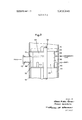
- FIG. 1 is a schematic elevational view of a preferring embodiment of inventive thin-film apparatus, specifically a thinfilm evaporator, equipped with a distributor ring arrangement designed according to the invention;
- FIG. 2 shows in fragmentary enlarged view details of the distributor ring arrangement utilized in the apparatus structure of FIG. 1.
- FIG. 1 there is shown a preferred embodiment of inventive thin-film apparatus, namely a vertically arranged thin-film evaporator, generally designated by reference numeral 10.
- This thin-film evaporator will be seen to embody a rotationally symmetrical treatment chamber 12 which is enclosed by a heatable or coolable jacket means 14.
- a vapor compartment 16 possessing a diameter approximately corresponding to the diameter of the treatment chamber or compartment 12 is arranged at the upper end of this treatment compartment.
- vaporchamber or compartment 16 The free upper end of vaporchamber or compartment 16 is sealed by means of a suitable cover member 18.'Further, the lower end to the treatment compartment 12 is'closed by a conically constructed discharge stud of connection 20.
- An inlet connection or stud 22 is arranged directly beneath the vapor compartment 16 at the jacket means 14 of the treatment compartment 12. Additionally, a vapor discharge connection or stud 24 is likewise provided at the jacket or outer wall of the vapor compartment 16.
- a rotor assembly 30 is coaxially arranged in the treatment compartment 12 as well as in the vapor compartment 16.
- This rotor assembly 30 will be seen to comprise a centrally arranged tubular portion 32, at the ends of which there are secured the shaft studs 36 and 38.
- the shaft stud 36 is rotatably mounted in a bearing means 40 arranged at the cover member 18, whereas the lower shaft stud 38 is supported in a bearing means 42 retained at the discharge connection by means of a plurality of webs 46.
- the aforementioned upper shaft stud 36 is operatively connected with a suitable drive motor 44.
- a plurality of axially extending vane means 34 are secured to the tubular portion 32, these vane means 34 also extending up to the region of the inner wall of the treatment chamber or compartment 12, as shown.
- a distributor ring arrangement 50 is provided at the rotor 30.
- This distributor ring arrangement 50 embodies a tubular member 52 disposed substantially coaxially with respect to rotor 30, and the diameter of such tubular member 52 being inset or recessed towards the center with respect to the diameter of rotor 30, Further, the ends ofthe tubular member 52 are bounded by annular or ring-shaped disc members 54 and 60, as shown, with the internal diameter of these disc members 54 and 60 approximately coinciding with the diameter of the tubular member 52.
- a plurality of axially extending vane portions 62 are secured to the lower portion of the tubular member 52, these vane portions 62 additionally extending radially up to the region of the inner wall of the treatment compartment 12. It will be seen that beginning at the lower disc member 60, at which there bear the lower, radially extending edges of the vane portions 62, the latter extend axially in the direction of the intermediate ring-shaped disc member 56 where such vane portions terminate at a spacing therefrom. Vane portions 62 together with the lower disc member 60 and the tubular member 52 form a distributor cham beror compartment 63.
- annular compartmentor space 66 the space between the intermediate ringshaped disc member 56 and the upper edges of the vane portions 62 is conveniently referred to as an annular compartmentor space 66, the significance of which will be more fully explained hereinafter.
- the distributor ring arrangement 50 is advantageously constructed and subdivided in such a manner that the axial extension of the expansion compartment 64, the therewith merging annular compartment or space 66, as well as the distributor chamber or compartment section 63 are approximately equal to one another. Additionally, it is of sig nificance that the axial extent of the annular compartment 66 approximately corresponds to the width of the inlet connection 22, as best shown in Fig. 2, and further, that the upper edges of the vane portions 62 are situated in a horizontally extending straight line with the lowermost turning point of the wall curvature of the inlet connection 22.
- the rotor assembly 30 is placed into rotational movement through the action of the drive motor 44.
- the jacket means 14 depending upon requirements, is either heated by a suitable heat carrying medium, or else fed with a suitable cooling medium for the purpose of cooling the treatment chamber 12.
- the material to be treated upon entering the treatment chamber 12 arrives at the annular compartment 66 of the distributor ring arrangement 50.
- the material dams up at the inlet region of the annular compartment 66, the intermediate ring-shaped disc member 56 preventing penetration into the expansion chamber or compartment 64.
- the material collected in the annular compartment 66 flows towards the lower ring-shaped disc member 60.
- the material penetrates into the distributor compartment 63 and at that location is entrained in the peripheral direction of the rotor assembly 30 by the vane portions or members 62.
- the material is thrown, through the action of the centrifugal forces, out of the distributor compartment 63 onto the inner wall of the treatment chamber 12.
- the frictional forces which prevail during the rotation of the rotor 30 between the vane portions 30 and the material have a delaying action with regard to the period of time that the material is slung or thrown away, in such a manner that the last material portions will practically first be thrown away from the rotor 30 after a complete revolution thereof.
- the vapors appearing in the annular or ring-shaped compartment 66 move through the gap 72 into the vapor compartment 16, whereby they initially expand in the expansion compartment 64 and thus separate any entrained droplets on the wall of the tubular member 52.
- the ring-shaped disc members 54 and 56 throw the droplets again onto the inner wall of the treatment chamber 12.
- the vapors appearing in the treatment chamber 12 flow through the space which is retained free by the tubular member 52, in the direction of the arrow 65,
- the inventive thin-film apparatus described by way of example as a thin film evaporator 10, possesses the advantage that the distributor ring arrangement 50 disposed in the evaporator ensures for a better distribution of the material to be treated upon the inner wall of the treatment chamber 12 directly beneath the inlet connection 22 of the evaporator 10. Due to the inventive measures there is achieved an increased utilization of the useful treatment surface, so that, for instance, there can, in turn, be attained a reduction of the manufacturing costs for a product.
- a thin-film apparatus for treatment of flowable materials comprising means defining an essentially vertically arranged, rotationally symmetrical treatment compartment bounded by a circumferentially entire wall portion, inlet connection means provided at an elevated position on said wall portion for the introduction of the material to be treated, rotor means arranged substantially coaxially within said treatment compartment, a distributor ring arrangement provided for said inlet connection means, said distributor ring arrangement being substantially concentrically secured to said rotor means and possessing a diameter which is inset with respect to the wall portion of said treatment compartment towards the axis of said rotor means, said distributor ring arrangement incorporating respective ring-shaped disc members arranged at its upper and lower ends, said ring-shaped disc members bounding in axial direction the space partially delimited by said distributor ring arrangement and said treatment compartment wall portion and forming together with said space a chamber for receiving and distributing the material introduced into said treatment compartment by said inlet means, said distributor ring arrangement further including an intermediate disc member which is secured thereto parallel to and axially spaced from said upper
Landscapes
- Chemical & Material Sciences (AREA)
- Chemical Kinetics & Catalysis (AREA)
- Vaporization, Distillation, Condensation, Sublimation, And Cold Traps (AREA)
- Processing And Handling Of Plastics And Other Materials For Molding In General (AREA)
Abstract
A thin-film apparatus for the treatment of flowable material which is of the type comprising an essentially vertically arranged rotationally symmetrical treatment chamber, the cylindrical wall portion of which possesses an inlet connection for the introduction of the material to be treated. Arranged within the treatment chamber is a substantially coaxial rotor. A distributor ring arrangement is associated with the inlet connection, such distributor ring arrangement being secured concentrically upon the rotor and being recessed or inset in diameter with respect to the treatment chamber wall towards the axis of the rotor. The distributor ring arrangement incorporates a respective ring-shaped or annular disc member at its upper and lower end. Furthermore, an intermediate disc member is secured to the distributor ring arrangement parallel to and at a spacing from the upper disc member, this intermediate disc member approximately coinciding in diameter with the upper disc member. Additionally, a plurality of axially extending vane portions which extend radially up to the treatment chamber wall are provided at the distributor ring arrangement. These vane portions, starting from the lower disc member, and viewed in axial direction, terminating at a distance from the intermediate disc member.
Description
United States Patent [72] Inventors Janos Miklos Gorbei;
Franc Dermota, both of Zurich, Switzerland [21] Appl. No. 27,254 [22] Filed Apr. 10, 1970 [45] Patented Jan. 11, 1972 [73] Assignee Luwa AG Zurich, Switzerland [32] Priority Apr. 15, 1969 [33] Switzerland [31] 5649/69 [54] THIN-FILM APPARATUS 4 Claims, 2 Drawing Figs.
[52] US. Cl 159/6 W, 159/43,159/13 A [51] Int. Cl 801d l/22 [50] Field of Search 159/6 W, 13 A,43; 202/236; 203/89; 62/347; 165/115, 118
[56] References Cited UNITED STATES PATENTS 2,807,321 9/1957 Schneider 159/13 A FOREIGN PATENTS 795,871 6/1958 Great Britain 159/13 A Primary Examiner-Norman Yudkoff Assistant Examiner-J. Sofer Attorney-Werner W. Kleeman ABSTRACTrA thin-film apparatus for the treatment of flowable material which is of the type comprising an essentially vertically arranged rotationally symmetrical treatment chamber, the cylindrical wall portion of which possesses an inlet connection for the introduction of the material to be treated. Arranged within the treatrnent chamber is a substantially coaxial rotor. A distributor ring arrangement is associated with the inlet connection, such distributor ring arrangement being secured concentrically upon the rotor and being recessed or inset in diameter with respect to the treatment chamber wall towards the axis of the rotor. The distributor ring arrangement incorporates a respective ring-shaped or annular disc member at its upper and lower end. Furthermore, an intermediate disc member is secured to the distributor ring arrangement parallel to and at a spacing from the upper disc member, this intermediate disc member approximately coinciding in diameter with the upper disc member. Additionally, a plurality of axially extending vane portions which extend radially up to the treatment chamber wall are provided at the distributor ring arrangement. These vane portions, starting from the lower disc member, and viewed in axial direction, terminating at a distance from the intermediate disc member.
[ "L. -VAPOR ,150 H -HEAT|NG OR ll'l I'll COOLING MEDIUM CONCENTRATE THIN-FILM APPARATUS BACKGROUND OF THE INVENTION The present invention relates to a new and improved thinfilm apparatus for the treatment of flowable materials which is of the type comprising an essentially vertically arranged, rotationally symmetrical treatment chamber, the cylindrical wall portion of which is equipped with an inlet connection or stud for the introduction of the material to be treated and a rotor arranged coaxially within the treatment chamber. A distributor ring arrangement which is disposed concentrically upon the rotor and in diameter is recessed or inset with respect to the treatment chamber wall towards the axis of the rotor is provided for the inlet connection. A respective ring-shaped disc member is located at the upper and lower ends of the distributor ring arrangement, these disc members delimiting in axial direction the space or compartment partially bounded by the distributor ring arrangement and the treatment chamber wall and which together with such form a space for receiving and distributing the material introduced into the treatment chamber.
A thin-film treatment apparatus is already known to the art which is of the type wherein its rotationally symmetrical, approximately vertically arranged treatment chamber is equipped with a coaxially arranged rotor. This rotor is equipped with a plurality of axially extending wiper blades which are directed radially towards the inner wall of the treatment chamber and serve to distribute the material to be treated upon the inner wall of such treatment chamber. Furthermore, this prior art thin-film apparatus is provided with a distributor ring which is mounted at the rotor and recessed or inset towards the axis of such rotor. This distributor ring is located opposite the inlet connection for the material appearing at the upper end of the treatment chamber at the cylindrical chamber wall portion. A respective ring-shaped disc member is secured at the axial ends of the distributor ring. This distributor ring forms together with the disc members and the treatment wall an annular compartment for receiving the material introduced into the treatment chamber. As soon as the material which flows downwardly along the outer wall of the distributor ring has reached the ring-shaped disc member which bounds the lower end of the distributor ring, then, such material is engaged by the disc member and thrown towards the treatment wall. The material then flows along the inner wall of the treatment chamber towards the outlet connection between the opening formed by the inner wall of the treatment chamber and the outer edge of the ring-shaped disc member.
However, this type construction of distributor ring has associated therewith the drawback that the material, which, upon entry into the heated treatment chamber, quickly expands due to the sudden thermal influences, that is to say, is subjected to a flash action, enters into the vapor compartment arranged above the distributor ring via the gap formed by the treatment wall and the ring-shaped discs. The withdrawn vapors are thus unnecessarily charged with droplets of material introduced into the treatment chamber. Furthermore, it has been found that in this type apparatus the distributor ring does not tendto uniformly spread the material throughout the entire periphery of the treatment wall, so that this treatment wall is only completely contacted by material throughout its entire periphery after a certain distance from the distributor ring. By virtue of the above-described disadvantages not only is there lost, together with the vapor current, valuable material to be treated, but also, by virtue of the unsatisfactory distribution of the material there results an incomplete utilization of the useful heat treatment surface. Both of these advantages considerably increase the expense of the heat treatment of the material.
SUMMARYOF THE INVENTION According, it a primary objective of the present invention to provide an improved thin-film apparatus of the mentioned type which effectively overcomes the aforementioned drawbacks of the prior art constructions.
Another, more specific object of the present invention relates to an improved thin-film apparatus which essentially prevents entrapment of the material to be treated by the vapor stream, provides for a much more uniform and complete distribution of material upon the treatment wall, and ensures for an economical, reliable and satisfactory processing of the material entering the thin-film apparatus.
Still another significant object of the present invention relates to an improved thin-film apparatus which is extremely simple in construction, relatively inexpensive to manufacture, highly reliable in operation, efficient in processing the material introduced for treatment into the apparatus, and ensures for increased economy in the overall treatment process.
Now, in order to implement these and still further objects of the invention, which will become more readily apparent as the description proceeds, the I inventive thin-film apparatus is generally manifested by the features that an intermediate disc member is secured at the distributor ring arrangement parallel to and at a spacing from the upper disc member thereof, this intermediate disc member possessing a diameter which approximately corresponds with the diameter of the upper disc member. Furthermore, a plurality of axially extending vane portions are arranged at the distributor ring, these vane portions further extending radially towards the treatment chamber wall and starting from the lower disc member, viewed in axial direction, terminating at a spacing from the aforementioned intermediate disc member.
It is indeed already known to the art to employ for thin-film evaporators having an internally disposed rotor, a rotationally symmetrical distributor ring for the purpose of distributing the material entering the treatment chamber upon the inner wall thereof. Furthermore, rotor vanes have been utilized heretofore for the purpose of uniformly spreading the material upon the inner wall of the treatment chamber. Both of the abovementioned prior art devices, however, could not operate satisfactorily since the distributor ring associated with the one inlet connection was not capable of wiping the material entering the treatment chamber to the desired degree upon the treatment wall, whereas the utilization of distributor vanes directly in front of the inlet opening was not completely satisfactory because, on the one hand, there was ascertained an increased foam and spray formation in the vapor compartment and, on the other hand, a large erosive wear of the distributor vanes.
The more uniform distribution of the material by virtue of the inventive apparatus, directly beneath the distributor ring, can be attributed to the unhindered entry of the material into the distributor ring and the directly thereafter engagement of such material by the vane portions at the distributor ring. The damming up action exerted upon the material by the rotating vane portions in the peripheral direction generates greater frictional forces between the vane portions and the material, so that with the same centrifugal forces with the inventive distributor ring a greater expenditure of time is necessary than with the previously known constructions, in order to throw the material upon the treatment wall. This time delay enables the material which is already at the operable region of the distributor ring to be uniformly applied over the entire periphery of the treatment wall.
BRIEF DESCRIPTION OF THE DRAWINGS The invention will be better understood and objects other than those set forth above will become apparent, when consideration is given to the following detailed description thereof. Such description makes reference to the annexed drawings therein:
FIG. 1 is a schematic elevational view of a preferring embodiment of inventive thin-film apparatus, specifically a thinfilm evaporator, equipped with a distributor ring arrangement designed according to the invention; and
FIG. 2 shows in fragmentary enlarged view details of the distributor ring arrangement utilized in the apparatus structure of FIG. 1.
DETAILED DESCRIPTION OF THE PREFERRED EMBODIMENTS Describing now the drawings, in FIG. 1 there is shown a preferred embodiment of inventive thin-film apparatus, namely a vertically arranged thin-film evaporator, generally designated by reference numeral 10. This thin-film evaporator will be seen to embody a rotationally symmetrical treatment chamber 12 which is enclosed by a heatable or coolable jacket means 14. A vapor compartment 16 possessing a diameter approximately corresponding to the diameter of the treatment chamber or compartment 12 is arranged at the upper end of this treatment compartment. The free upper end of vaporchamber or compartment 16 is sealed by means of a suitable cover member 18.'Further, the lower end to the treatment compartment 12 is'closed by a conically constructed discharge stud of connection 20. An inlet connection or stud 22 is arranged directly beneath the vapor compartment 16 at the jacket means 14 of the treatment compartment 12. Additionally, a vapor discharge connection or stud 24 is likewise provided at the jacket or outer wall of the vapor compartment 16.
Now, a rotor assembly 30 is coaxially arranged in the treatment compartment 12 as well as in the vapor compartment 16. This rotor assembly 30 will be seen to comprise a centrally arranged tubular portion 32, at the ends of which there are secured the shaft studs 36 and 38. The shaft stud 36 is rotatably mounted in a bearing means 40 arranged at the cover member 18, whereas the lower shaft stud 38 is supported in a bearing means 42 retained at the discharge connection by means of a plurality of webs 46. The aforementioned upper shaft stud 36 is operatively connected with a suitable drive motor 44. A plurality of axially extending vane means 34 are secured to the tubular portion 32, these vane means 34 also extending up to the region of the inner wall of the treatment chamber or compartment 12, as shown.
Continuing, as best observed by referring to FIG. 2, it will be recognized that at the region of the inlet connection 22 a distributor ring arrangement 50 is provided at the rotor 30. This distributor ring arrangement 50 embodies a tubular member 52 disposed substantially coaxially with respect to rotor 30, and the diameter of such tubular member 52 being inset or recessed towards the center with respect to the diameter of rotor 30, Further, the ends ofthe tubular member 52 are bounded by annular or ring- shaped disc members 54 and 60, as shown, with the internal diameter of these disc members 54 and 60 approximately coinciding with the diameter of the tubular member 52.
Apart from the foregoing, it will also be observed that the marginal edges of these disc members 54 and 60 which limit the outer circumference or periphery therefore extend up to the region of the inner wall of the treatment compartment 12 and leave free a respective gap 70 and 72 between the treatment wall and the disc members 54, 60. An intermediate ringshaped or annular disc member 56 is arranged parallel and at a spacing below from the upper ring member 54 coaxially with respect to the tubular member 52, the dimensions of the intermediate ring-shaped disc 56 substantially corresponding to those of the ring- shaped disc members 54 and 60. The ringshaped disc members 54 and 56 partially delimit together with the wall of the treatment chamber 12 and the tubular member 52 an expansion space or compartment 64. A plurality of axially extending vane portions 62 are secured to the lower portion of the tubular member 52, these vane portions 62 additionally extending radially up to the region of the inner wall of the treatment compartment 12. It will be seen that beginning at the lower disc member 60, at which there bear the lower, radially extending edges of the vane portions 62, the latter extend axially in the direction of the intermediate ring-shaped disc member 56 where such vane portions terminate at a spacing therefrom. Vane portions 62 together with the lower disc member 60 and the tubular member 52 form a distributor cham beror compartment 63.
Furthermore, the space between the intermediate ringshaped disc member 56 and the upper edges of the vane portions 62 is conveniently referred to as an annular compartmentor space 66, the significance of which will be more fully explained hereinafter. The distributor ring arrangement 50 is advantageously constructed and subdivided in such a manner that the axial extension of the expansion compartment 64, the therewith merging annular compartment or space 66, as well as the distributor chamber or compartment section 63 are approximately equal to one another. Additionally, it is of sig nificance that the axial extent of the annular compartment 66 approximately corresponds to the width of the inlet connection 22, as best shown in Fig. 2, and further, that the upper edges of the vane portions 62 are situated in a horizontally extending straight line with the lowermost turning point of the wall curvature of the inlet connection 22.
During operation of the thin film evaporator 10 heretofore described and shown, the rotor assembly 30 is placed into rotational movement through the action of the drive motor 44. At the same time, the jacket means 14, depending upon requirements, is either heated by a suitable heat carrying medium, or else fed with a suitable cooling medium for the purpose of cooling the treatment chamber 12. The material to be treated upon entering the treatment chamber 12 arrives at the annular compartment 66 of the distributor ring arrangement 50. The material dams up at the inlet region of the annular compartment 66, the intermediate ring-shaped disc member 56 preventing penetration into the expansion chamber or compartment 64. In the event that the material expands to such a degree because such materialis heated much too quickly, so that this material then penetrates through the gap or space 72 into the expansion chamber 64, then the material which has penetrated mostly in the form of foam into this expansion chamber 64 will be deposited upon the bounding wall of such chamber, and thereafter will be thrown back upon the treatment chamber wall. Due to the action of gravity the material again arrives at the annular compartment or chamber 66.
Now the material collected in the annular compartment 66 flows towards the lower ring-shaped disc member 60. The material penetrates into the distributor compartment 63 and at that location is entrained in the peripheral direction of the rotor assembly 30 by the vane portions or members 62. During rotation of the distributor ring 50 the material is thrown, through the action of the centrifugal forces, out of the distributor compartment 63 onto the inner wall of the treatment chamber 12. The frictional forces which prevail during the rotation of the rotor 30 between the vane portions 30 and the material have a delaying action with regard to the period of time that the material is slung or thrown away, in such a manner that the last material portions will practically first be thrown away from the rotor 30 after a complete revolution thereof. Due to this delaying action there is achieved that the material will be uniformly distributed directly beneath the distributor ring arrangement 50 upon the entire periphery of the inner wall of the treatment chamber 12, and consequently, there will be insured for a better utilization of the available treatment surface. The material which is thrown onto the inner wall of the treatment chamber 12 flows through the gap 70 into the treatment compartment 12. The vanes 34 spread this material into a thin layer upon the inner wall of the treatment compartment 12, where it then tends to flow towards the discharge or outlet connection 20 under the influence of gravity.
The vapors appearing in the annular or ring-shaped compartment 66 move through the gap 72 into the vapor compartment 16, whereby they initially expand in the expansion compartment 64 and thus separate any entrained droplets on the wall of the tubular member 52. The ring-shaped disc members 54 and 56 throw the droplets again onto the inner wall of the treatment chamber 12. The vapors appearing in the treatment chamber 12 flow through the space which is retained free by the tubular member 52, in the direction of the arrow 65,
tainer.
In contrast to the previously known similar type apparatuses, the inventive thin-film apparatus described by way of example as a thin film evaporator 10, possesses the advantage that the distributor ring arrangement 50 disposed in the evaporator ensures for a better distribution of the material to be treated upon the inner wall of the treatment chamber 12 directly beneath the inlet connection 22 of the evaporator 10. Due to the inventive measures there is achieved an increased utilization of the useful treatment surface, so that, for instance, there can, in turn, be attained a reduction of the manufacturing costs for a product.
While there is shown and described present preferred emvariously embodied and practiced within the scope of the following claims.
What is claimed:
A thin-film apparatus for treatment of flowable materials, comprising means defining an essentially vertically arranged, rotationally symmetrical treatment compartment bounded by a circumferentially entire wall portion, inlet connection means provided at an elevated position on said wall portion for the introduction of the material to be treated, rotor means arranged substantially coaxially within said treatment compartment, a distributor ring arrangement provided for said inlet connection means, said distributor ring arrangement being substantially concentrically secured to said rotor means and possessing a diameter which is inset with respect to the wall portion of said treatment compartment towards the axis of said rotor means, said distributor ring arrangement incorporating respective ring-shaped disc members arranged at its upper and lower ends, said ring-shaped disc members bounding in axial direction the space partially delimited by said distributor ring arrangement and said treatment compartment wall portion and forming together with said space a chamber for receiving and distributing the material introduced into said treatment compartment by said inlet means, said distributor ring arrangement further including an intermediate disc member which is secured thereto parallel to and axially spaced from said upper disc member, said intermediate disc member approximately con-esponding in diameter to said upper disc member, a plurality of axially extending vane portions arranged at said distributor ring arrangement and also extending radially towards said treatment chamber wall portion, said vane portions extending axially from said lower disc member and terminating at an axially spaced location from said intermediate disc member.
2. A thin-film apparatus for treatment of flowable material as defined in claim 1, wherein said vane portions include end portions facing towards said intermediate disc member, the spacing between said upper disc member and said intermediate disc member as well as the length of said vane portions being intermediate disc member and said end portions of said vane portions confronting said intermediate disc member, said lastmentioned spacing receiving the material from the inlet means and being coextensive therewith.
3. A thin-film apparatus for treatment of flowable materials as defined in claim 1, wherein said vane portions incorporate end portions confronting said intermediate disc member, the spacing between said intermediate disc member and said end portions of said vane portions confronting said intermediate disc member approximately equaling the internal width of said inlet connection means and being coextensive therewith.
4. A thin-film apparatus for treatment of flowable materials as defined in claim 3, wherein said end portions of said vane portions confronting said intermediate disc member are in substantially horizontal alignment with the lowermost point of the curvature of the wall portion of said inlet connection means.
approximately equal to the spacing between said,
Claims (4)
1. A thin-film apparatus for treatment of flowable materials, comprising means defining an essentially vertically arranged, rotationally symmetrical treatment compartment bounded by a circumferentially entire wall portion, inlet connection means proviDed at an elevated position on said wall portion for the introduction of the material to be treated, rotor means arranged substantially coaxially within said treatment compartment, a distributor ring arrangement provided for said inlet connection means, said distributor ring arrangement being substantially concentrically secured to said rotor means and possessing a diameter which is inset with respect to the wall portion of said treatment compartment towards the axis of said rotor means, said distributor ring arrangement incorporating respective ring-shaped disc members arranged at its upper and lower ends, said ringshaped disc members bounding in axial direction the space partially delimited by said distributor ring arrangement and said treatment compartment wall portion and forming together with said space a chamber for receiving and distributing the material introduced into said treatment compartment by said inlet means, said distributor ring arrangement further including an intermediate disc member which is secured thereto parallel to and axially spaced from said upper disc member, said intermediate disc member approximately corresponding in diameter to said upper disc member, a plurality of axially extending vane portions arranged at said distributor ring arrangement and also extending radially towards said treatment chamber wall portion, said vane portions extending axially from said lower disc member and terminating at an axially spaced location from said intermediate disc member.
2. A thin-film apparatus for treatment of flowable material as defined in claim 1, wherein said vane portions include end portions facing towards said intermediate disc member, the spacing between said upper disc member and said intermediate disc member as well as the length of said vane portions being approximately equal to the spacing between said intermediate disc member and said end portions of said vane portions confronting said intermediate disc member, said last-mentioned spacing receiving the material from the inlet means and being coextensive therewith.
3. A thin-film apparatus for treatment of flowable materials as defined in claim 1, wherein said vane portions incorporate end portions confronting said intermediate disc member, the spacing between said intermediate disc member and said end portions of said vane portions confronting said intermediate disc member approximately equaling the internal width of said inlet connection means and being coextensive therewith.
4. A thin-film apparatus for treatment of flowable materials as defined in claim 3, wherein said end portions of said vane portions confronting said intermediate disc member are in substantially horizontal alignment with the lowermost point of the curvature of the wall portion of said inlet connection means.
Applications Claiming Priority (1)
| Application Number | Priority Date | Filing Date | Title |
|---|---|---|---|
| CH564969A CH515063A (en) | 1969-04-15 | 1969-04-15 | Thin film apparatus |
Publications (1)
| Publication Number | Publication Date |
|---|---|
| US3633645A true US3633645A (en) | 1972-01-11 |
Family
ID=4297112
Family Applications (1)
| Application Number | Title | Priority Date | Filing Date |
|---|---|---|---|
| US27254A Expired - Lifetime US3633645A (en) | 1969-04-15 | 1970-04-10 | Thin-film apparatus |
Country Status (4)
| Country | Link |
|---|---|
| US (1) | US3633645A (en) |
| JP (1) | JPS4928832B1 (en) |
| CH (1) | CH515063A (en) |
| DE (1) | DE2013462C3 (en) |
Cited By (2)
| Publication number | Priority date | Publication date | Assignee | Title |
|---|---|---|---|---|
| US4054485A (en) * | 1974-10-09 | 1977-10-18 | Luwa Ag | Thin film apparatus |
| US5185060A (en) * | 1989-07-26 | 1993-02-09 | Shinko Pantec Co., Ltd. | Film evaporator |
Citations (2)
| Publication number | Priority date | Publication date | Assignee | Title |
|---|---|---|---|---|
| US2807321A (en) * | 1952-11-04 | 1957-09-24 | Bayer Ag | Feeding means for evaporators |
| GB795871A (en) * | 1954-05-04 | 1958-06-04 | Bayer Ag | A process for the recovery of dry substances from their solutions or suspensions by evaporation in thin layers |
-
1969
- 1969-04-15 CH CH564969A patent/CH515063A/en not_active IP Right Cessation
-
1970
- 1970-03-20 DE DE2013462A patent/DE2013462C3/en not_active Expired
- 1970-04-10 US US27254A patent/US3633645A/en not_active Expired - Lifetime
- 1970-04-15 JP JP45031629A patent/JPS4928832B1/ja active Pending
Patent Citations (2)
| Publication number | Priority date | Publication date | Assignee | Title |
|---|---|---|---|---|
| US2807321A (en) * | 1952-11-04 | 1957-09-24 | Bayer Ag | Feeding means for evaporators |
| GB795871A (en) * | 1954-05-04 | 1958-06-04 | Bayer Ag | A process for the recovery of dry substances from their solutions or suspensions by evaporation in thin layers |
Cited By (2)
| Publication number | Priority date | Publication date | Assignee | Title |
|---|---|---|---|---|
| US4054485A (en) * | 1974-10-09 | 1977-10-18 | Luwa Ag | Thin film apparatus |
| US5185060A (en) * | 1989-07-26 | 1993-02-09 | Shinko Pantec Co., Ltd. | Film evaporator |
Also Published As
| Publication number | Publication date |
|---|---|
| JPS4928832B1 (en) | 1974-07-30 |
| CH515063A (en) | 1971-11-15 |
| DE2013462A1 (en) | 1971-09-09 |
| DE2013462B2 (en) | 1977-07-21 |
| DE2013462C3 (en) | 1978-03-02 |
Similar Documents
| Publication | Publication Date | Title |
|---|---|---|
| US2546381A (en) | Apparatus for concentrating liquids | |
| US3808701A (en) | Apparatus for drying fluent materials | |
| US1853682A (en) | Atomizing apparatus | |
| US2639747A (en) | Rotary granulating machine | |
| US3633645A (en) | Thin-film apparatus | |
| US2542270A (en) | Scraper apparatus for centrifugal evaporators | |
| US1589097A (en) | Apparatus for continuously separating liquids from solids | |
| US3625273A (en) | Thin film apparatus having a two-part heat treatment chamber | |
| US3030657A (en) | Device for granulation | |
| US4054485A (en) | Thin film apparatus | |
| US3242969A (en) | Polymer desolventizer of the rotary wiped falling film type | |
| US2625320A (en) | Centrifuge for rapid extraction of fine particles from suspensions | |
| US3199574A (en) | Falling film-evaporators and rotor structure therefor | |
| US2010902A (en) | Process and apparatus for converting liquid substances into the form of granules | |
| GB1266250A (en) | ||
| US3741466A (en) | Jet centrifuge | |
| GB1254501A (en) | Installation for treating liquids | |
| US1775036A (en) | Dehydrator | |
| US2304221A (en) | Drying apparatus | |
| US2084487A (en) | Method and means for recovering gold | |
| GB1251946A (en) | ||
| US2176142A (en) | Cooling means for grinding mill disks | |
| US1931496A (en) | Centrifugal machine | |
| GB930141A (en) | Apparatus for mixing and agglomerating pulverulent to granular materials | |
| JP3266299B2 (en) | Thin film evaporator |