US3568254A - Apparatus for deep draw molding - Google Patents
Apparatus for deep draw molding Download PDFInfo
- Publication number
- US3568254A US3568254A US760757A US3568254DA US3568254A US 3568254 A US3568254 A US 3568254A US 760757 A US760757 A US 760757A US 3568254D A US3568254D A US 3568254DA US 3568254 A US3568254 A US 3568254A
- Authority
- US
- United States
- Prior art keywords
- plug
- sheet
- cavity
- mold
- sides
- Prior art date
- Legal status (The legal status is an assumption and is not a legal conclusion. Google has not performed a legal analysis and makes no representation as to the accuracy of the status listed.)
- Expired - Lifetime
Links
Images

Classifications
-
- B—PERFORMING OPERATIONS; TRANSPORTING
- B29—WORKING OF PLASTICS; WORKING OF SUBSTANCES IN A PLASTIC STATE IN GENERAL
- B29C—SHAPING OR JOINING OF PLASTICS; SHAPING OF MATERIAL IN A PLASTIC STATE, NOT OTHERWISE PROVIDED FOR; AFTER-TREATMENT OF THE SHAPED PRODUCTS, e.g. REPAIRING
- B29C51/00—Shaping by thermoforming, i.e. shaping sheets or sheet like preforms after heating, e.g. shaping sheets in matched moulds or by deep-drawing; Apparatus therefor
- B29C51/04—Combined thermoforming and prestretching, e.g. biaxial stretching
- B29C51/06—Combined thermoforming and prestretching, e.g. biaxial stretching using pressure difference for prestretching
-
- B—PERFORMING OPERATIONS; TRANSPORTING
- B29—WORKING OF PLASTICS; WORKING OF SUBSTANCES IN A PLASTIC STATE IN GENERAL
- B29C—SHAPING OR JOINING OF PLASTICS; SHAPING OF MATERIAL IN A PLASTIC STATE, NOT OTHERWISE PROVIDED FOR; AFTER-TREATMENT OF THE SHAPED PRODUCTS, e.g. REPAIRING
- B29C51/00—Shaping by thermoforming, i.e. shaping sheets or sheet like preforms after heating, e.g. shaping sheets in matched moulds or by deep-drawing; Apparatus therefor
- B29C51/10—Forming by pressure difference, e.g. vacuum
Definitions
- the present invention relates to an apparatus for forming hollow articles and more particularly to an apparatus for producing relatively deep, thin wall thermoplastic containers.
- Plug assist thermoforming of containers is well-known in the art. It involves clamping a heated sheet of thermoplastic material over the open mouth of a mold cavity which conforms to the shape of the container, mechanically drawing a portion of the heated sheet into the cavity by means of an advancing plug to partially form the container, and then pneumatically moving the par- -tially formed container ofi the plug against the cavity walls to finish form the container.
- a heated sheet of thermoplastic material over the open mouth of a mold cavity which conforms to the shape of the container, mechanically drawing a portion of the heated sheet into the cavity by means of an advancing plug to partially form the container, and then pneumatically moving the par- -tially formed container ofi the plug against the cavity walls to finish form the container.
- the sheet is in place over the mouth of the cavity and before plug Contact, it is usually prestretched away from the cavity either as a result of the weight of the sheet itself when the cavity faces downwardly, or by means of a positive gas pressure acting against the sheet when the cavity is facing upwardly.
- This prestretching is to avoid the costly approach of utilizing an excessively thick sheet to provide adequate material to form the deep container, and to avoid prevmature contact or chilling of the hot sheet by the mold surfaces.
- the container to be formed is noncircular, eg., rectangular, it has been found that the sheet stretches non-uniformly at this stage of the process, i.e.,
- the portion of the sheet which initially contacts theplug surface has a tendency to become trapped and to remain there against the plug face throughout the forming operation, thereby resulting in a container having a bottom which is thicker than that of the sides.
- This effect is, of course, a function of the temperature and surface characteristics of the plug face, but these parameters are often diicult to control, especially with relatively small plug cross sections.
- vAdherence of the sheet to the plug surface also occurs along the sides of the plug as it penetrates deeper into the cavity, thereby producing localized thickness variations and-drag marks in the finished container. Also,
- thermoforming plug which effectively overcomes all of these past diiiiculties and permits deep draw thermofonning of containers having improved distribution of plastic material therein.
- thermoforming plug conguration It-is an additional object of this invention to provide an improved thermoforming plug conguration.
- an apparatus for forming a relatively deep, thin walled container from a sheet of thermoplastic material comprising a mold including a cavity having a ⁇ periphery generally conforming to the shapeof the container, a contoured plug disposed opposite tothe mold, having a plurality of sides with two of the sides having depressions formed therein, means for actuating the plug to draw a predetermined area of the plastic sheet into the cavity of the mold to provide a partially formed container and means for expanding the partially formed container against the wall of the cavity of the mold.
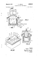
- FIG. I is a semi-diagrammatical sectional view of apparatus embodying the present invention at ⁇ an early stage in the thermoforming process
- FIG. II is a view taken along the line II-II of FIG. l after the plug has engaged the sheet;
- FIG. III is a perspective view illustrating the position fof the sheet with respect to the advancing plug in the stage of the process depicted in FIG. II;
- FIG. IV is a view similar to FIGS. I and II illustrating 70 the nal step in forming the container;
- FIG. V is a perspective view of an alternate form of the plug of the present invention.
- FIG. VI is a sectional view of the plug of FIGS. I-IV.
- the container is to be a generally rectangular box being about 2.01/2 inches wide, 37 inches long and 20%. inches deep.
- the thermoplastic which is in the form of a sheet S having an initial thickness of about 230y mils, is clamped against the top surface 12 of mold 10 by means of clamping plate 14 having a central opening in which the sheet is exposed.
- the central opening generally conforms in shape to that of the cross section of the mold cavity which in the present preferred embodiment is rectangular.
- Sheet S has been previously brought into association with suitable conventional heating means (not shown) such as electrical resistance heaters, in a manner well-known to those skilled in the art, in order to heat the sheet to a temperature appropriate to the particular plastic and place it in a deformable state.
- suitable conventional heating means such as electrical resistance heaters
- Mold has a rectangularly shaped cavity 16 therein having peripheral dimensions which generally conform to the shape of the container being formed.
- the pressure in cavity 16 may be increased or decreased by means of conduit 18 communicating with an intermediate fluid space 20, which in turn communicates with cavity 16 by means of small passages 22 which are appropriately spaced to perform an expansion of the plastic material when suction is applied in space 20 during a later step of the process.
- Conduit 18 is connected to manifold 19' having three branches therein, i.e., 21 which is connected to a source of pressurized fluid (not shown), 23 which is connected to a vacuum source (not shown) and 25 which is open to the atmosphere.
- Suitable valves V are located in each of the three branches 21, 23 and 25 so as to provide for varying the pressure in space 20- from theupstream level at the ends of branches 21, 23 and 25.
- contoured plug 28 is provided, and is initially disposed opposite mold 10 and mounted on vertically reciprocable platen 30, which in turn is connected by means of shaftV 32 to a suitable actuating mechanism (not shown).
- Punch 28 is elongated in cross section, and in the embodiment shown has a plurality of sides, being generally rectangular in configuration, except that it has somewhat the general shape of an hour glass or dogbone depending on the direction from which it is viewed, and which is achieved by means of depressions formed in two oppositely disposed sides.
- plug 28 is solid in cross section but could be hollow and comprises a bottom wall 34, a pair of oppositely disposed elongated sides 36. Each side 36 has (FIG.
- Plug 28 further comprises a pair of integral, oppositely disposed short sides 42 extending between elongated sides 36 and connected thereto along the longitudinally extending edges 38 of sides 36. Oppositely disposed short sides 42 similarly have two longitudinally extending edges 44 and two laterally extending edges 46. The two pairs of oppositely disposed elongated and short sides 36 and 42 extend upwardly from the periphery of bottom wall 34. Plug 28 further comprises top wall 48 extending around the upper extremities of the pairs of oppositely disposed elongated and short sides. As depicted in FIG. III, each of the oppositely disposed elongated sides taper slightly inwardly from each of their two longitudinally extending edges 38 toward the center lines of these sides.
- Plug 28 is heated in a well-known manner to a desired temperature, for example, by means of electrical heating .elements incorporated therein.
- the heating elements may 4 metal, wood or plastic. In the present embodiment aluminum is employed.
- the mold may be continuously vented, i.e., the fluid being introduced to the cavity may be allowed to escape between the top surface 12 of the mold and the underside of sheet S.
- This initial stretching of the material takes place freely over the entirearea within the clamped portion of the sheet Without chilling by contact with the mold.
- the portions of the clamped sheet in the area of the center of the elongated sides stretches and thins to a greater degree than that of the remainder of the sheet, and consequently, the sheet thickness after this stretching is non-uniform throughout the clamped area.
- heated plug 28 is caused to descend into the ballooned plastic bubble by vertically reciprocating platen 30 to which the plug is attached. It will be understood that the reverse is also satisfactory, i.e., upward plug movement into a downwardly facing plastic bubble.
- valve V on line 25 of manifold 19 which opens tothe atmosphere may be partially opened to bleed olf air and maintain the pres sure within the cavity at the desired level.
- the inwardly tapered elongated sides 36 of plug 28 also aid in maintaining the plastic material out of substantial contact with the major portion of the elongated sides of punch 28, except for the contact which must occur along the longitudinally extending edges thereof in order to draw the plastic into the mold cavity.
- the vsecondary billow A which vis that maintained during plug descent, may ⁇ bev retained ,essentially untilthe punchreaches itspoint of maximum descent and bottoms iout inthe mold cavity.
- va vacuum ⁇ is drawn on ythe mold cavity by opening the'valve on conduit Lv,2.3- which connects ,with the vacuum source.
- the hot plastic material immediately snaps to the shape of the cavity resulting in a finish formed container C.
- the plastic loses its heat rapidly since the mold is relatively cool, the mold temperature being in the 'order of about 1Z0-150 F.
- the punch V starts its ascent and moves to its starting position spaced opposite the die mouth.
- Rapid removal of the formed part is preferably accomplislied, following closingiof the vacuum valve, by opening the air pressure valve in conduit 2,1 to introduce pressurized iiuid into the mold cavity around the periphery 'of the formed article, While at vthe'same'time lifting the clamping member 14 to a point where the article can be completely removed from the 'mo-ld.
- This fluid blow oi following the vacuumforining operation also helps to remove any residual heat from the mold, to thus insure maintenance of a fast operating cycle and consequently high production 'rates with no lost time waiting for the mold to cool.
- FIG. V is shown an alternate form of the unique plug of the present invention.
- Plug 50 of this embodiment is elongated as was that of the previous embodiment, having a portion of reduced cross sectional area 52 in the center thereof caused by inwardly extending side portions 54, but also including centrally oriented depressed portions 56 formed in the oppositely dispose-d short sides thereof.
- the plug configuration of the present invention is uniquely effective in plug assist thermoforming of both large volume containers such as refrigerator cabinets as well as small volume containers such as cigarette packages, wherein the thermoplastic sheet must be drawn a rather substantial distance into the mold cavity.
- These relatively deep articles include those wherein the total overall length measured in a direction parallel to the axis of the body of the article is in excess of about inches for sheet thicknesses in the range of between about 100 to 2.50 mils. Described another way, the depth of the mold cavity in deep draw molding ranges from between about 0.5 to 5 times that of the dimension of the shortest side of the mouth of the cavity. With such containers, substantial stretching of the sheet is necessary if an economical article is to be manufactured without requiring an abnormal increase in the thickness of the thermoplastic sheet.
- the heated sheet tends to become trapped on whatever surface of the forming equipment with which it comes into contact and thereafter can no longer be effectively thinned by stretching. This is especially true of the front face of the plug, since contact therewith generally eliminates any possibility o-f the material thereafter moving into. the side(s) of the container being formed.
- the plug of the present invention provides for a reduced amount of initial surface contact with the sheet to the extent of the inward slope of the plug sides, consistent with plug dimensions adequate to avoid excessive thinning and fracture of the sheet during the final expansion step.
- the reduced cross sectional configuration which extends along the entire length of the plug also permits maintenance of the sheet billow, and therefore, the resulting stretching action which ti provides until the plug proceeds almost the entire distance into the cavity.
- Any plug having a plurality of sides with at least two of the sides having depressions formed therein is broadly withycylindrical shapes) having centrally oriented depressions ,formed in two sides thereof and preferably ⁇ oppositely disposed sides may be ,satisfactorily used according to the invention.
- the invention is particularly applicable togenerally rectangular shapes with rounded edges and corners,
- vji/llerein Y represents the length of the short side and Z represents the length of the elongated side of the plug cross section 0 represents the angle of taper which the portion of elongated side adjoining short side Y makes with the vertical and is defined by the relationship tan
- the reduced cross section in the center area of the plug having a dimension defined by X in FIG. VI may range between 0 ⁇ .5 ot 0.9 times Y.
- the plug of the present invention is broadly useful in all types of plug assist thermoforming operations. This includes those systems wherein drawing is acomplished by dual cushions of air emanating from both the plug and mold cavity repectively or wherein final forming is by means of pressurized gas emanating from the punch or by means of vacuum imposed on the mold cavity.
- thermoforming systems utilizing the plug design of the present invention it is desirable to have the dimension of the outer periphery of the punch approach the dimensions of the cavity as closely as possible, in order that the material has a minimum distance to travel in moving from the punch surface to the cavity walls.
- the reduced cross section of the plug of the present invention achieves this, yet provides adequate space to maintain the secondary billow during the actual drawing operation.
- Apparatus for forming a relatively deep, thin walled container from a sheet of thermoplastic material comprising:
- a generally rectangular plug disposed opposite to said mold said plug comprising a bottom wall, a pair of oppositely disposed elongated sides, each side having two longitudinally extending edges and two laterally extending edges, a pair of oppositely disposed short sides extending between said oppositely disposed short sides extending between said oppositely disposed elongated sides along the longitudinally extending edges of said elongated sides, said oppositely disposed short sides having two longitudinally extending edges and two laterally extending edges, said pairs of oppositely disposed elongated and short sides extending upwardly from the periphery of said bottom wall, a top wall extendling around the upper extremities of said pairs of oppositely disposed elongated and short sides, each of said oppositely disposed elongated sides tapering slightly inwardly from cach of the two longitudinally extending edges of said elongated sides toward the centers of said sides; (c) means connected to said top Wall of the plug for actuating said plug to draw a predetermined area of the plastic sheet into the
Landscapes
- Engineering & Computer Science (AREA)
- Mechanical Engineering (AREA)
- Blow-Moulding Or Thermoforming Of Plastics Or The Like (AREA)
Abstract
A SPECIALLY CONTOURED THERMOFORMING PLUG HAVING TWO SIDES WITH DEPRESSIONS FORMED THEREIN IN ORDER TO PROVIDE IMPROVED DISTRIBUTION OF MATERIAL IN DEEP DRAW MOLDED ARTICLES.
Description
-T..J.s1'oLKl APPARATUS FOR vDEEP DRAW MODDING Marcha, 1971 2 sheets-sheet A1 y Filed sept'. 19, 196s o PRESSURE F/G 2| y P VACUUM Y F/alz INVENTOR. THOMAS J. STOLKI Ew z y L ATTZRNEY:
i Mmh 9, 1971 T. q. Smm 3,568,254
APPARATUS FOR DEEP DRAW MOLDING yFiled Sept. 19, 1968 2 Sheets-Sheet 2 THOMAS JQ STOLK LATT NEY Patented Mar. 9, 1971 3,568,254 APPARATUS FOR DEEP DRAW MOLDING Thomas J. Stolki, Wilbraham, Mass., assignor to Monsanto Company, St. Louis, Mo. Filed Sept. 19, 1968, Ser. No. 760,757 Int. Cl. B29'c 17/03, 17/04 U.S. Cl. 18--19 7 Claims ABSTRACT F THE DISCLOSURE A specially contoured thermoforming plug having two sides with depressions formed therein in order to provide improved distribution of material in deep draw molded articles.
The present invention relates to an apparatus for forming hollow articles and more particularly to an apparatus for producing relatively deep, thin wall thermoplastic containers.
Plug assist thermoforming of containers is well-known in the art. It involves clamping a heated sheet of thermoplastic material over the open mouth of a mold cavity which conforms to the shape of the container, mechanically drawing a portion of the heated sheet into the cavity by means of an advancing plug to partially form the container, and then pneumatically moving the par- -tially formed container ofi the plug against the cavity walls to finish form the container. In forming deep containers, when the sheet is in place over the mouth of the cavity and before plug Contact, it is usually prestretched away from the cavity either as a result of the weight of the sheet itself when the cavity faces downwardly, or by means of a positive gas pressure acting against the sheet when the cavity is facing upwardly. The purpose of this prestretching is to avoid the costly approach of utilizing an excessively thick sheet to provide adequate material to form the deep container, and to avoid prevmature contact or chilling of the hot sheet by the mold surfaces. When the container to be formed is noncircular, eg., rectangular, it has been found that the sheet stretches non-uniformly at this stage of the process, i.e.,
lmore in the center area of the wide axis of the rectangularly shaped clamped sheet portion, than in the remaining areas of the sheet. This uneven reduction in sheet thickness eventually appears in the walls of the nished article and results in a structurally weak container.
In addition, the portion of the sheet which initially contacts theplug surface has a tendency to become trapped and to remain there against the plug face throughout the forming operation, thereby resulting in a container having a bottom which is thicker than that of the sides. This effect is, of course, a function of the temperature and surface characteristics of the plug face, but these parameters are often diicult to control, especially with relatively small plug cross sections.
vAdherence of the sheet to the plug surface also occurs along the sides of the plug as it penetrates deeper into the cavity, thereby producing localized thickness variations and-drag marks in the finished container. Also,
-since the die is usually maintained cool to rapidly set the plastic after final forming, it is necessary to keep the sheet `portion adjacent vthe clamp away from the mouth of the cavity for as long as possible during the ldrawing stage of the process. To achieve vthese latter effects, a positive pressure is usually maintained in the cavity during plug entry to billow and stretch the sheet upwardly in the opposite direction from plug movement yandfto keep the sheet out of contact with the plug and cavity surfaces for as long as possible before final expansion of the sheet against the cavity walls. However, after the plug has proceeded beyond the cavity mouth, the
space between it and the clamp holding the sheet in place is determinative of the area available for maintaining the billowing sheet, and this is often insufficient for sustaining the billow up through the time the plug bot- 5 toms in the cavity.
Prior attempts to overcome early elimination of the billow involved reducing the plug cross section for a given die size, in order to provide increased clearance between the plug and cavity Walls, but this did not solve the problem and can create additional problems since if the plug size is excessively reduced, thinning in other areas of the container will occur asa result of insuiiicient material to form the container being drawn into the mold by the advancing plug.
Now there has been developed a unique thermoforming plug which effectively overcomes all of these past diiiiculties and permits deep draw thermofonning of containers having improved distribution of plastic material therein.
Accordingly, it is an object of this invention to overcome the prior art diiculties in forming thin walled containers, especiaily those having deep drawn thermoformed portion wherein the surface area of the finished container is substantially greater than that of the area of the starting sheet material.
It is an additional object of this invention to provide a deep draw molding apparatus for obtaining improved uniformity of distribution of material in the finished container.
It-is an additional object of this invention to provide an improved thermoforming plug conguration.
It is another object of this invention to minimize contact of a thermoplastic sheet portion with the surfaces of a mechanical deforming plug or die until the plug has almost completely entered the die in a deep draw thermoforming operation, in order to improve material distribution in an upper body section of the container.
It is a further object of this invention to provide an apparatus of the aforenoted type which can produce both shallow and deep drawn containers having improved uniformity of wall thickness, at high production capacities without increasing the unitcost per container.
Other objects of'this invention will in'part be obvious and will in part appear hereinafter.
These and other objects are accomplished by providing an apparatus for forming a relatively deep, thin walled container from a sheet of thermoplastic material comprising a mold including a cavity having a `periphery generally conforming to the shapeof the container, a contoured plug disposed opposite tothe mold, having a plurality of sides with two of the sides having depressions formed therein, means for actuating the plug to draw a predetermined area of the plastic sheet into the cavity of the mold to provide a partially formed container and means for expanding the partially formed container against the wall of the cavity of the mold.
In describing the overall invention, reference-will be made to preferred embodiments illustrated in the accompanying drawings in which:
FIG. I is a semi-diagrammatical sectional view of apparatus embodying the present invention at `an early stage in the thermoforming process;
FIG. II is a view taken along the line II-II of FIG. l after the plug has engaged the sheet;
FIG. III is a perspective view illustrating the position fof the sheet with respect to the advancing plug in the stage of the process depicted in FIG. II;
FIG. IV is a view similar to FIGS. I and II illustrating 70 the nal step in forming the container;
FIG. V is a perspective view of an alternate form of the plug of the present invention; and
FIG. VI is a sectional view of the plug of FIGS. I-IV.
With reference to the drawings wherein identical nuvrnerals refer to identical parts, there is illustrated an ap* paratus and method for forming a relatively deep, thin walled container from a sheet of thermoplastic material. In the embodiment shown in FIGS. I-IV, the container is to be a generally rectangular box being about 2.01/2 inches wide, 37 inches long and 20%. inches deep. The thermoplastic which is in the form of a sheet S having an initial thickness of about 230y mils, is clamped against the top surface 12 of mold 10 by means of clamping plate 14 having a central opening in which the sheet is exposed. The central opening generally conforms in shape to that of the cross section of the mold cavity which in the present preferred embodiment is rectangular. Sheet S has been previously brought into association with suitable conventional heating means (not shown) such as electrical resistance heaters, in a manner well-known to those skilled in the art, in order to heat the sheet to a temperature appropriate to the particular plastic and place it in a deformable state.
Mold has a rectangularly shaped cavity 16 therein having peripheral dimensions which generally conform to the shape of the container being formed. In accordance with the method depicted, the pressure in cavity 16 may be increased or decreased by means of conduit 18 communicating with an intermediate fluid space 20, which in turn communicates with cavity 16 by means of small passages 22 which are appropriately spaced to perform an expansion of the plastic material when suction is applied in space 20 during a later step of the process. Conduit 18 is connected to manifold 19' having three branches therein, i.e., 21 which is connected to a source of pressurized fluid (not shown), 23 which is connected to a vacuum source (not shown) and 25 which is open to the atmosphere. Suitable valves V are located in each of the three branches 21, 23 and 25 so as to provide for varying the pressure in space 20- from theupstream level at the ends of branches 21, 23 and 25.
As an essential element of the present invention, contoured plug 28 is provided, and is initially disposed opposite mold 10 and mounted on vertically reciprocable platen 30, which in turn is connected by means of shaftV 32 to a suitable actuating mechanism (not shown). Punch 28 is elongated in cross section, and in the embodiment shown has a plurality of sides, being generally rectangular in configuration, except that it has somewhat the general shape of an hour glass or dogbone depending on the direction from which it is viewed, and which is achieved by means of depressions formed in two oppositely disposed sides. In further detail, plug 28 is solid in cross section but could be hollow and comprises a bottom wall 34, a pair of oppositely disposed elongated sides 36. Each side 36 has (FIG. III) two longitudinally extending edges 38 and two laterally extending edges 40. Plug 28 further comprises a pair of integral, oppositely disposed short sides 42 extending between elongated sides 36 and connected thereto along the longitudinally extending edges 38 of sides 36. Oppositely disposed short sides 42 similarly have two longitudinally extending edges 44 and two laterally extending edges 46. The two pairs of oppositely disposed elongated and short sides 36 and 42 extend upwardly from the periphery of bottom wall 34. Plug 28 further comprises top wall 48 extending around the upper extremities of the pairs of oppositely disposed elongated and short sides. As depicted in FIG. III, each of the oppositely disposed elongated sides taper slightly inwardly from each of their two longitudinally extending edges 38 toward the center lines of these sides.
In operating the apparatus of the present invention, after heated sheet S has been clamped across the open end of cavity 16 in mold 10, a positive pressure is introduced through conduit 18, intermediate space 20 and passages 22 into cavity 16, so as to billow sheet 'S upwardly as depicted in FIG. I and thereby stretch the material and thin it accordingly. It should be noted that the orientation of the apparatus may be reversed, i.e., the plug situated below the mold and the cavity facing downwardly, whereupon the wei-ght of the sheet may be adequate to prestretch it without the requirement of fluid introduction into the cavity. Though the system in FIG. I is depicted as utilizing a hermetically sealed mold cavity, it should be understood that the mold may be continuously vented, i.e., the fluid being introduced to the cavity may be allowed to escape between the top surface 12 of the mold and the underside of sheet S. This initial stretching of the material takes place freely over the entirearea within the clamped portion of the sheet Without chilling by contact with the mold. However, as previously mentioned, the portions of the clamped sheet in the area of the center of the elongated sides stretches and thins to a greater degree than that of the remainder of the sheet, and consequently, the sheet thickness after this stretching is non-uniform throughout the clamped area.
After the sheet has been prestretched by billowing the clamped portion upwardly over the mouth of the mold, heated plug 28 is caused to descend into the ballooned plastic bubble by vertically reciprocating platen 30 to which the plug is attached. It will be understood that the reverse is also satisfactory, i.e., upward plug movement into a downwardly facing plastic bubble.
When the plug initially contacts the ballooned sheet the extent of contact is reduced over that which would be obtained if the plug were truly rectangular, due to the inwardly tapering elongated plug sides. The amount of plastic trapped on the front face of the plug is therefore reduced, and consequently, additional plastic in the center of the sheet is available (to the extent of the reduction of contact with the plug) to move outwardly and upwardly into the portion of the sheet which has been previously thinned and which will form the upper sidewall portion of the container body.
As the plug moves into the mold cavity the pressure will increase because of the reduction in volume therein, and to avoid rupturing the bubble, valve V on line 25 of manifold 19 which opens tothe atmosphere may be partially opened to bleed olf air and maintain the pres sure within the cavity at the desired level. As seen in FIGS. II and III, the inwardly tapered elongated sides 36 of plug 28 also aid in maintaining the plastic material out of substantial contact with the major portion of the elongated sides of punch 28, except for the contact which must occur along the longitudinally extending edges thereof in order to draw the plastic into the mold cavity. As plug 28 proceeds into cavity 16 and further mechanically deforms ballooning sheet S to partially form the container, hot plastic is displaced upwardly from adjacent the area of reduced plug cross section to offset the thinning which has previously occurred. The positive pressure within the cavity provides a cushion to maintain the material in a ballooned condition, thus keeping the sheet portions away from the surface of the mold cavity, and especially away from the peripheral edge of the mouth of the cavity as the plug continues to advance to its position of maximum descent as shown in PIG. IV Stretch is thus imparted to the material and due to its freedom from engagement with'the mold and punch surfaces and displacement in the area around the center of the tapered sides of the plug, an improved uniformity of thickness of plastic in the formed container results. Because of the added clearance provided between the plug surface and the cavity wall by the inwardly tapering sides of v the punch,L the vsecondary billow Awhich vis that maintained during plug descent, may `bev retained ,essentially untilthe punchreaches itspoint of maximum descent and bottoms iout inthe mold cavity.
As soon as punch 2x8 has reached its maximum descent,
`the valve on the cavity vent line to atmosphere vis closed,
and simultaneously va vacuum `is drawn on ythe mold cavity by opening the'valve on conduit Lv,2.3- which connects ,with the vacuum source. The hot plastic material immediately snaps to the shape of the cavity resulting in a finish formed container C. `The plastic loses its heat rapidly since the mold is relatively cool, the mold temperature being in the 'order of about 1Z0-150 F. Also, simultaneously with the starting of the vacuum, the punch Vstarts its ascent and moves to its starting position spaced opposite the die mouth.
Rapid removal of the formed part ispreferably accomplislied, following closingiof the vacuum valve, by opening the air pressure valve in conduit 2,1 to introduce pressurized iiuid into the mold cavity around the periphery 'of the formed article, While at vthe'same'time lifting the clamping member 14 to a point where the article can be completely removed from the 'mo-ld. This fluid blow oi following the vacuumforining operation also helps to remove any residual heat from the mold, to thus insure maintenance of a fast operating cycle and consequently high production 'rates with no lost time waiting for the mold to cool.
In FIG. V is shown an alternate form of the unique plug of the present invention. Plug 50 of this embodiment is elongated as was that of the previous embodiment, having a portion of reduced cross sectional area 52 in the center thereof caused by inwardly extending side portions 54, but also including centrally oriented depressed portions 56 formed in the oppositely dispose-d short sides thereof.
The above description and particularly the drawings are set forth for purposes of illustration only and are not to be taken in a limited sense.
The plug configuration of the present invention is uniquely effective in plug assist thermoforming of both large volume containers such as refrigerator cabinets as well as small volume containers such as cigarette packages, wherein the thermoplastic sheet must be drawn a rather substantial distance into the mold cavity. These relatively deep articles include those wherein the total overall length measured in a direction parallel to the axis of the body of the article is in excess of about inches for sheet thicknesses in the range of between about 100 to 2.50 mils. Described another way, the depth of the mold cavity in deep draw molding ranges from between about 0.5 to 5 times that of the dimension of the shortest side of the mouth of the cavity. With such containers, substantial stretching of the sheet is necessary if an economical article is to be manufactured without requiring an abnormal increase in the thickness of the thermoplastic sheet. During drawing, the heated sheet tends to become trapped on whatever surface of the forming equipment with which it comes into contact and thereafter can no longer be effectively thinned by stretching. This is especially true of the front face of the plug, since contact therewith generally eliminates any possibility o-f the material thereafter moving into. the side(s) of the container being formed. The plug of the present invention provides for a reduced amount of initial surface contact with the sheet to the extent of the inward slope of the plug sides, consistent with plug dimensions adequate to avoid excessive thinning and fracture of the sheet during the final expansion step. The reduced cross sectional configuration which extends along the entire length of the plug also permits maintenance of the sheet billow, and therefore, the resulting stretching action which ti provides until the plug proceeds almost the entire distance into the cavity.
Any plug having a plurality of sides with at least two of the sides having depressions formed therein is broadly withycylindrical shapes) having centrally oriented depressions ,formed in two sides thereof and preferably `oppositely disposed sides may be ,satisfactorily used according to the invention. The invention is particularly applicable togenerally rectangular shapes with rounded edges and corners,
nwherein stretching lbecause of lackof symmetry is unusually non-uniform. Preferable limits of this configuration are depicted in the cross sectional view of FIG. VI,
vji/llerein Y represents the length of the short side and Z represents the length of the elongated side of the plug cross section 0 represents the angle of taper which the portion of elongated side adjoining short side Y makes with the vertical and is defined by the relationship tan The reduced cross section in the center area of the plug having a dimension defined by X in FIG. VI may range between 0`.5 ot 0.9 times Y.
' The plug of the present invention is broadly useful in all types of plug assist thermoforming operations. This includes those systems wherein drawing is acomplished by dual cushions of air emanating from both the plug and mold cavity repectively or wherein final forming is by means of pressurized gas emanating from the punch or by means of vacuum imposed on the mold cavity.
In thermoforming systems utilizing the plug design of the present invention, it is desirable to have the dimension of the outer periphery of the punch approach the dimensions of the cavity as closely as possible, in order that the material has a minimum distance to travel in moving from the punch surface to the cavity walls. The reduced cross section of the plug of the present invention achieves this, yet provides adequate space to maintain the secondary billow during the actual drawing operation.
It is obvious that many variations may be made in the invention set forth above without departing from the spirit and scope of the invention as hereinafter claimed.
What I claim is:
1. In an apparatus for forming a relatively deep, thin walled article from a sheet of thermoplastic material utilizing a mold having a cavity conforming to the shape of the article, a plug arranged for movement into the cavity to draw a predetermined portion of the sheet into the cavity to partially form the article and means to expand the partially formed article against the wall of the cavity into the final form of the article, the improvement which comprises inwardly tapered oppositely disposed side wall portions of the plug for minimizing the surface contact of the plug with the sheet during partial forming of the article.
2. The apparatus of claim 1 wherein the plug has a generally rectangular cross section with rounded surfaces at its corners and at the junctions of the edges of its sides.
3. Apparatus for forming a relatively deep, thin walled container from a sheet of thermoplastic material comprising:
(a) a mold including a cavity having a periphery generally conforming to the shape of the container;
(b) a generally rectangular plug disposed opposite to said mold, said plug comprising a bottom wall, a pair of oppositely disposed elongated sides, each side having two longitudinally extending edges and two laterally extending edges, a pair of oppositely disposed short sides extending between said oppositely disposed short sides extending between said oppositely disposed elongated sides along the longitudinally extending edges of said elongated sides, said oppositely disposed short sides having two longitudinally extending edges and two laterally extending edges, said pairs of oppositely disposed elongated and short sides extending upwardly from the periphery of said bottom wall, a top wall extendling around the upper extremities of said pairs of oppositely disposed elongated and short sides, each of said oppositely disposed elongated sides tapering slightly inwardly from cach of the two longitudinally extending edges of said elongated sides toward the centers of said sides; (c) means connected to said top Wall of the plug for actuating said plug to draw a predetermined area of the plastic sheet into the cavity of the mold to partially form said container, and (d) means for expanding said partially formed container against the =wal1 of the cavity of the mold t0 nish form the container. 4. The apparatus of claim 3 wherein the angle of inward taper of the elongated sides of the plug conforms to the relationship m110=(0.25-2)ZX 5. The apparatus of claim 3 wherein the cavity of the mold has a `generally rectangular cross section.
to the cavity of the mold for regulating the pressure in said cavity'during formation of the partially formed container. 4
References Cited l UNITED STATES PATENTS 3/1952 Stevens 18-19 2,983,955 5/1961 Gajdoish 18-19X 3,400,111 9/ 1968 Schwartz 18-19 2,910,728 11/1959 Rowe, Jr. 18-19 2,917,783 v12/1959 Olson et al. 2,952,875 9/1960 Herrick 18-19 2,973,558 3/1961 Stratton, Jr 264-89 3,267,521 8/1966 Kostur 18--19 3,470,281 9/ 1969 Knowles 18-19 OTHER REFERENCES Product Engineering M-D-September 1960 (pp. 164- 167), Author: R. E. Kostur.
I. SPENCER OVERHO-LSER, Primary Examiner R. L. SPICER, JR., Assistant Examiner
Applications Claiming Priority (1)
| Application Number | Priority Date | Filing Date | Title |
|---|---|---|---|
| US76075768A | 1968-09-19 | 1968-09-19 |
Publications (1)
| Publication Number | Publication Date |
|---|---|
| US3568254A true US3568254A (en) | 1971-03-09 |
Family
ID=25060093
Family Applications (1)
| Application Number | Title | Priority Date | Filing Date |
|---|---|---|---|
| US760757A Expired - Lifetime US3568254A (en) | 1968-09-19 | 1968-09-19 | Apparatus for deep draw molding |
Country Status (1)
| Country | Link |
|---|---|
| US (1) | US3568254A (en) |
Cited By (26)
| Publication number | Priority date | Publication date | Assignee | Title |
|---|---|---|---|---|
| DE2313501A1 (en) * | 1972-03-21 | 1973-09-27 | Shell Int Research | PROCESS AND FORM FOR MANUFACTURING HOLLOW BODIES FROM THERMOPLASTIC FILM |
| US3929953A (en) * | 1972-03-21 | 1975-12-30 | Shell Oil Co | Method for forming noncircular thermoplastic cupped articles |
| US3933562A (en) * | 1970-07-13 | 1976-01-20 | United States Steel Corporation | Method of laminating a plastic sheet onto a surface of a hollow body |
| FR2474387A1 (en) * | 1980-01-30 | 1981-07-31 | Lechaine Marcel | Tools for making large thermo:formed mouldings - using residual mould cavity pressure to develop forming pressures against compression mould face |
| EP0135333A2 (en) * | 1983-08-19 | 1985-03-27 | AMP INCORPORATED (a New Jersey corporation) | A spherically shaped switch assembly öand apparatus and method for forming same |
| US4536148A (en) * | 1984-06-26 | 1985-08-20 | Cosden Technology, Inc. | Apparatus for making a thin walled container from a plastic resin |
| US4917903A (en) * | 1987-01-15 | 1990-04-17 | Kurt Mente | Apparatus for producing decorative seams on films shaped using a drawing method |
| US20050196567A1 (en) * | 2001-03-12 | 2005-09-08 | Toyo Seikan Kaisha, Ltd. | Heat-resistant resin container and method of producing the same |
| DE102006020673A1 (en) * | 2006-05-04 | 2007-11-08 | Illig Maschinenbau Gmbh & Co. Kg | Deep-drawing thermoplastic film container, includes clamping and precurving film section spaced from container edge-forming region before introducing stretching auxiliary, giving even wall thickness |
| US20130056298A1 (en) * | 2010-05-18 | 2013-03-07 | Heinrich Gillet Gmbh | Exhaust gas muffler for internal combustion engines and deep drawing tool therefor |
| US20130241117A1 (en) * | 2012-03-14 | 2013-09-19 | Soeren Oemann Lind | Method of manufacturing an article by molding |
| US9511690B2 (en) | 2012-04-23 | 2016-12-06 | Global Ip Holdings, Llc | Cargo management system including a vehicle load floor having a cellulose-based core and made by a composite, compression molding process and having a wood grain finish |
| US9527268B2 (en) | 2012-04-23 | 2016-12-27 | Global Ip Holdings, Llc | Method of making a sandwich-type composite panel having a cellulose-based core and a living hinge and panel obtained by performing the method |
| US9539958B2 (en) | 2012-04-23 | 2017-01-10 | Global Ip Holdings, Llc | Assembly including a compression-molded, composite panel having a cellulose-based core and a hinged mounting flange |
| US9567037B2 (en) | 2012-05-24 | 2017-02-14 | Global Ip Holdings, Llc | Deep-drawn marine hull having a sandwich structure with a cellulose-based core and watercraft utilizing same |
| US9707725B2 (en) | 2013-02-08 | 2017-07-18 | Global Ip Holdings, Llc | Method of making a sandwich-type, compression-molded, composite component having a cellulose-based core and improved surface appearance |
| US9770849B2 (en) | 2013-02-08 | 2017-09-26 | Global Ip Holdings, Llc | Method of making a sandwich-type, compression-molded, composite component having improved surface appearance |
| US9873488B2 (en) | 2012-05-24 | 2018-01-23 | Global Ip Holdings Llc | Deep-drawn marine hull having a sandwich structure and watercraft utilizing same |
| US9908281B1 (en) | 2015-08-31 | 2018-03-06 | Converter Manufacturing, Llc | Formed thermoplastic article having smooth edges |
| US10166704B2 (en) | 2013-02-08 | 2019-01-01 | Global Ip Holdings, Llc | Method of making a laminated trim component at a pair of spaced first and second molding stations |
| US10279512B2 (en) | 2013-02-08 | 2019-05-07 | Global Ip Holdings, Llc | Method of making a laminated trim component at a molding station |
| US10532499B2 (en) | 2013-02-08 | 2020-01-14 | Global Ip Holdings, Llc | Method of making a laminated trim component |
| US10618203B2 (en) | 2013-02-08 | 2020-04-14 | Global Ip Holdings, Llc | Method of making a trimmed, laminated trim component |
| US11214035B2 (en) | 2012-05-24 | 2022-01-04 | Global Ip Holdings, Llc | Marine decking with sandwich-type construction and method of making same |
| US11518136B2 (en) | 2012-05-24 | 2022-12-06 | Global Ip Holdings, Llc | Marine decking with sandwich-type construction and method of making same |
| US11560911B2 (en) | 2017-06-06 | 2023-01-24 | Global Ip Holdings, Llc | Method of making marine decking |
-
1968
- 1968-09-19 US US760757A patent/US3568254A/en not_active Expired - Lifetime
Cited By (41)
| Publication number | Priority date | Publication date | Assignee | Title |
|---|---|---|---|---|
| US3933562A (en) * | 1970-07-13 | 1976-01-20 | United States Steel Corporation | Method of laminating a plastic sheet onto a surface of a hollow body |
| DE2313501A1 (en) * | 1972-03-21 | 1973-09-27 | Shell Int Research | PROCESS AND FORM FOR MANUFACTURING HOLLOW BODIES FROM THERMOPLASTIC FILM |
| US3859028A (en) * | 1972-03-21 | 1975-01-07 | Shell Oil Co | Mandrel for plug assisted shaping of thermpolastic sheets |
| US3929953A (en) * | 1972-03-21 | 1975-12-30 | Shell Oil Co | Method for forming noncircular thermoplastic cupped articles |
| FR2474387A1 (en) * | 1980-01-30 | 1981-07-31 | Lechaine Marcel | Tools for making large thermo:formed mouldings - using residual mould cavity pressure to develop forming pressures against compression mould face |
| EP0135333A2 (en) * | 1983-08-19 | 1985-03-27 | AMP INCORPORATED (a New Jersey corporation) | A spherically shaped switch assembly öand apparatus and method for forming same |
| EP0135333A3 (en) * | 1983-08-19 | 1986-04-09 | AMP INCORPORATED (a New Jersey corporation) | A spherically shaped switch assembly öand apparatus and method for forming same |
| US4536148A (en) * | 1984-06-26 | 1985-08-20 | Cosden Technology, Inc. | Apparatus for making a thin walled container from a plastic resin |
| US4917903A (en) * | 1987-01-15 | 1990-04-17 | Kurt Mente | Apparatus for producing decorative seams on films shaped using a drawing method |
| US20050196567A1 (en) * | 2001-03-12 | 2005-09-08 | Toyo Seikan Kaisha, Ltd. | Heat-resistant resin container and method of producing the same |
| US7655179B2 (en) * | 2001-03-12 | 2010-02-02 | Toyo Seikan Kaisha, Ltd. | Heat-resistant resin container and method of producing the same |
| DE102006020673A1 (en) * | 2006-05-04 | 2007-11-08 | Illig Maschinenbau Gmbh & Co. Kg | Deep-drawing thermoplastic film container, includes clamping and precurving film section spaced from container edge-forming region before introducing stretching auxiliary, giving even wall thickness |
| EP1854614A1 (en) * | 2006-05-04 | 2007-11-14 | ILLIG Maschinenbau GmbH & Co. KG | Method for deep drawing a container made of a heated thermoplastic film and moulding tool for performing the process |
| US20130056298A1 (en) * | 2010-05-18 | 2013-03-07 | Heinrich Gillet Gmbh | Exhaust gas muffler for internal combustion engines and deep drawing tool therefor |
| US9440276B2 (en) * | 2010-05-18 | 2016-09-13 | Tenneco Gmbh | Exhaust gas muffler for internal combustion engines and deep drawing tool therefor |
| US20130241117A1 (en) * | 2012-03-14 | 2013-09-19 | Soeren Oemann Lind | Method of manufacturing an article by molding |
| US8999216B2 (en) * | 2012-03-14 | 2015-04-07 | Siemens Aktiengesellschaft | Method of manufacturing an article by molding |
| US20150174834A1 (en) * | 2012-03-14 | 2015-06-25 | Siemens Aktiengesellschaft | Mold for manufacturing a component |
| US9919482B2 (en) * | 2012-03-14 | 2018-03-20 | Siemens Aktiengesellschaft | Mold for manufacturing a component |
| US9539958B2 (en) | 2012-04-23 | 2017-01-10 | Global Ip Holdings, Llc | Assembly including a compression-molded, composite panel having a cellulose-based core and a hinged mounting flange |
| US9511690B2 (en) | 2012-04-23 | 2016-12-06 | Global Ip Holdings, Llc | Cargo management system including a vehicle load floor having a cellulose-based core and made by a composite, compression molding process and having a wood grain finish |
| US9776536B2 (en) | 2012-04-23 | 2017-10-03 | Global Ip Holdings, Llc | Cargo management system including a vehicle load floor having a cellulose-based core with a cellular structure and made by a composite, compression molding process and having a wood grain finish |
| US9878526B2 (en) | 2012-04-23 | 2018-01-30 | Global Ip Holdings, Llc | Method of making a sandwich-type composite panel having a cellulose-based core and a living hinge and panel obtained by performing the method |
| US9527268B2 (en) | 2012-04-23 | 2016-12-27 | Global Ip Holdings, Llc | Method of making a sandwich-type composite panel having a cellulose-based core and a living hinge and panel obtained by performing the method |
| US9567037B2 (en) | 2012-05-24 | 2017-02-14 | Global Ip Holdings, Llc | Deep-drawn marine hull having a sandwich structure with a cellulose-based core and watercraft utilizing same |
| US11518136B2 (en) | 2012-05-24 | 2022-12-06 | Global Ip Holdings, Llc | Marine decking with sandwich-type construction and method of making same |
| US11214035B2 (en) | 2012-05-24 | 2022-01-04 | Global Ip Holdings, Llc | Marine decking with sandwich-type construction and method of making same |
| US9873488B2 (en) | 2012-05-24 | 2018-01-23 | Global Ip Holdings Llc | Deep-drawn marine hull having a sandwich structure and watercraft utilizing same |
| US10166704B2 (en) | 2013-02-08 | 2019-01-01 | Global Ip Holdings, Llc | Method of making a laminated trim component at a pair of spaced first and second molding stations |
| US10279512B2 (en) | 2013-02-08 | 2019-05-07 | Global Ip Holdings, Llc | Method of making a laminated trim component at a molding station |
| US10532499B2 (en) | 2013-02-08 | 2020-01-14 | Global Ip Holdings, Llc | Method of making a laminated trim component |
| US10618203B2 (en) | 2013-02-08 | 2020-04-14 | Global Ip Holdings, Llc | Method of making a trimmed, laminated trim component |
| US9770849B2 (en) | 2013-02-08 | 2017-09-26 | Global Ip Holdings, Llc | Method of making a sandwich-type, compression-molded, composite component having improved surface appearance |
| US9707725B2 (en) | 2013-02-08 | 2017-07-18 | Global Ip Holdings, Llc | Method of making a sandwich-type, compression-molded, composite component having a cellulose-based core and improved surface appearance |
| US10076865B2 (en) * | 2015-08-31 | 2018-09-18 | Converter Manufacturing, Llc | Ram-based methods for forming thermoplastic article having smooth edges |
| US9908281B1 (en) | 2015-08-31 | 2018-03-06 | Converter Manufacturing, Llc | Formed thermoplastic article having smooth edges |
| US10399268B2 (en) * | 2015-08-31 | 2019-09-03 | Converter Manufacturing, Llc | Ram-based methods for forming thermoplastic article having smooth edges |
| US20190358890A1 (en) * | 2015-08-31 | 2019-11-28 | Converter Manufacturing, Llc | Ram-Based Methods for Forming Thermoplastic Article Having Smooth Edges |
| US10562680B2 (en) | 2015-08-31 | 2020-02-18 | Converter Manufacturing, Llc | Formed thermoplastic article having a smoothly-curved distal periphery |
| US10562222B2 (en) | 2015-08-31 | 2020-02-18 | Converter Manufacturing, Llc | Formed thermoplastic article having smooth edges |
| US11560911B2 (en) | 2017-06-06 | 2023-01-24 | Global Ip Holdings, Llc | Method of making marine decking |
Similar Documents
| Publication | Publication Date | Title |
|---|---|---|
| US3568254A (en) | Apparatus for deep draw molding | |
| US2973558A (en) | Method for deep-draw vacuum forming | |
| EP0010847B1 (en) | Method and apparatus for thermoforming thermoplastic foam articles | |
| US3342914A (en) | Method and apparatus for deep draw molding | |
| US3218379A (en) | Process and apparatus for forming plastic cups or the like | |
| JPH09507178A (en) | Method and apparatus for producing thermoplastic containers, especially bottles | |
| US3172927A (en) | Method and apparatus for molding plastic articles | |
| US3291874A (en) | Method and apparatus for forming articles from plastic sheet material | |
| US4034054A (en) | Process for thermoforming hollow articles | |
| US4308711A (en) | Packaging apparatus and techniques for forming closure-tops | |
| US3634182A (en) | Preformed plastic blank for making open mouth plastic containers | |
| US3362045A (en) | Apparatus for the manufacture of hollow plastic articles | |
| US4165357A (en) | Method of shaping plastics foils | |
| US4013437A (en) | Method for forming glass bottles | |
| US3732050A (en) | Apparatus for forming preferably cup-shaped hollow bodies by drawing a material capable of being formed by heat | |
| US3441983A (en) | Apparatus for formation of thermoplastic sheet into a cup-like container | |
| US3336424A (en) | Thermoplastic sheet formation | |
| WO1983001412A1 (en) | Improvements relating to containers | |
| US4308086A (en) | Apparatus for the preparation of hollow plastic articles with a base cup | |
| JPS61152531A (en) | Packaging machine | |
| US4207134A (en) | Apparatus for the preparation of hollow plastic articles | |
| US4234302A (en) | Apparatus for the preparation of hollow plastic articles | |
| US3439078A (en) | Process for stamping thermoplastic elements | |
| US4225304A (en) | Apparatus for the preparation of hollow plastic articles | |
| US3394208A (en) | Method and apparatus for forming fill receiving pockets in webs |