US3502945A - Switching control apparatus - Google Patents
Switching control apparatus Download PDFInfo
- Publication number
- US3502945A US3502945A US661352A US3502945DA US3502945A US 3502945 A US3502945 A US 3502945A US 661352 A US661352 A US 661352A US 3502945D A US3502945D A US 3502945DA US 3502945 A US3502945 A US 3502945A
- Authority
- US
- United States
- Prior art keywords
- group
- wires
- relay
- conductors
- connector
- Prior art date
- Legal status (The legal status is an assumption and is not a legal conclusion. Google has not performed a legal analysis and makes no representation as to the accuracy of the status listed.)
- Expired - Lifetime
Links
Images


Classifications
-
- H—ELECTRICITY
- H01—ELECTRIC ELEMENTS
- H01H—ELECTRIC SWITCHES; RELAYS; SELECTORS; EMERGENCY PROTECTIVE DEVICES
- H01H67/00—Electrically-operated selector switches
- H01H67/22—Switches without multi-position wipers
- H01H67/26—Co-ordinate-type selector switches not having relays at cross-points but involving mechanical movement, e.g. cross-bar switch, code-bar switch
-
- G—PHYSICS
- G05—CONTROLLING; REGULATING
- G05B—CONTROL OR REGULATING SYSTEMS IN GENERAL; FUNCTIONAL ELEMENTS OF SUCH SYSTEMS; MONITORING OR TESTING ARRANGEMENTS FOR SUCH SYSTEMS OR ELEMENTS
- G05B19/00—Programme-control systems
- G05B19/02—Programme-control systems electric
- G05B19/04—Programme control other than numerical control, i.e. in sequence controllers or logic controllers
- G05B19/08—Programme control other than numerical control, i.e. in sequence controllers or logic controllers using plugboards, cross-bar distributors, matrix switches, or the like
Definitions
- Selection of relays to be energized is effected by the insertion of first diode plugs into a matrix to interconnect selected conductors of first and second conductor groups of the matrix to provide an energization circuit for the selected relay.
- De-energization of the selected relays is also effected through the matrix by way of further diode plugs interconnecting selected conductors of the first and a third group of matrix conductors. Successive conductors of the first group may be supplied with current sequentially.
- This invention relates to switching control apparatus, and more particularly to apparatus for controlling different switching functions of electrical control circuits.
- the commonest known arrangement for automatic sequential control of switching functions employs cam-operated switches, each connected to a respective relay device, which are operated by respective cams mounted on a common rotary shaft.
- cams By suitably arranging the cams on the shaft the switches can be operated in any desired sequence on rotation of the shaft.
- Such an arrangement suffers from two disadvantages. In the first place it is difficult to arrange for accurate operation of the cam switches at required times, since the precise time of operation of the switches is very sensitive to the setting and shape of the cams. In the second place, and probably more importantly, such arrangements cannot easily be adjusted: in order to change the time of operation of a given cam operated switch it is necessary to change the setting of the respective cam on the rotary shaft.
- a further object is to provide a control apparatus in which control circuits may be energized in a pre-settable sequence, the sequence being readily ascertainable.
- a switching control apparatus comprising a matrix of first and second groups of conductors arranged so that each conductor of the first group crosses but does not contact each conductor of the second group; respective connector means for connecting as required any selected conductor of the first group to any selected conductor of the second group; respective input lines connected to respective conductors of the first group, and respective output lines connected to respective conductors of the second group, whereby an electrical circuit including any selected conductor of the first group Hce and its respective input line is completed through such conductor of the second group and its respective output lines as is selectively connected by said connector means to said selected conductor of the first group.
- the selective switching means are preferably operative to make an electrical connection to each said input line in a predetermined sequence.
- the connector means may be adjusted without difliculty so as to change the sequence of energisation of any of the control circuits relative to the other control circuits.
- the connector means comprise, respective connector plugs and the first and second groups of conductors are carried by an insulating member having respective sockets therein, corresponding to each crossing point of the conductors, for the removable insertion of respective said connector plugs as required, said connector plugs when inserted in a said socket connecting a selected conductor of the first group to a selected conductor of the second group.
- FIGURE 1 is a purely schematic diagram of a simple form of control apparatus according to the invention.
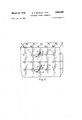
- FIGURE 2 is a partly cut away view of part of a preferred form of conductor-carrying member or matrix board for use in the embodiment of FIGURE 3;
- FIGURE 3 is a schematic circuit diagram of control apparatus according to a preferred embodiment of the invention.
- FIGURE 4 is a front elevation of a control apparatus according to the invention housed in a control console.
- the relay control apparatus shown in FIGURE 1 is designed to complete, in a predetermined sequence, energising circuits to respective output lines 0L1 0L6.
- the output lines 0L1 0L6 each control different functions, for example different technical services in an hotel.
- Control of the output lines 0L1 0L6 is effected through a matrix board 1 comprising an insulating laminar support member 2 which supports two groups of conductors C, D disposed in different parallel planes, for example, on opposite sides of the support member 2, or embedded in the member 2.
- the first group of conductors C comprises an array of parallel wires 0 c c c spaced apart at equal intervals in one said plane
- the second group D comprises an array of parallel wires d d d d extending perpendicular to the wires of the first group C and spaced apart at equal intervals in the other said plane.
- the two groups of conductors C, D are superimposed, so that each wire 0 -0 of the first group C crosses, but does not contact, each wire ai -d of the second group D.
- Each wire c -c of the first group C is connected through a respective input line IL1 IL-S to sequential switching means comprising a movable contact 3 which is moved in the direction of arrow 4 to make electrical contact with each input line IL1 1L8 in turn.
- the movable contact 3 is connected to one terminal 5 of a direct current source 5 so that an electrical circuit is completed through each of the wires c c of the first group C in sequence.
- the movable contact 3 most conveniently comprises a rotary arm which is moved in successive steps at equal time intervals to contact the input lines IL1 1L8 sequentially.
- the wires d -d of the second group D are connected to the respective ouput lines 0L1 0L6. Any selected wire 0 -0 may be connected to any selected wire al -d by means of appropriate connectors.
- Such connectors may comprise switches connecting respective wires c -c to respective wires ti -d or, as in the illustrated embodiment, may comprise removable connector plugs 6 which are inserted in selected sockets 7 provided in the support member 2 adjacent each crossing point of the wires a c and a -d Each connector plug 6 when so inserted selected wires of the first and second groups C, D.
- FIG- URE 1 connector plugs 6 are shown in position to connect wires c and d d and d c and d 0' and d 0 and d2.
- the terminal 5 is connected to each of the wires c c of the first group C in turn for equal successive time intervals t through the movable contact 3, and as a result electrical circuits to the output lines 0L1 0L6 are completed in a sequence dependent on the positions of the connector plugs 6.
- output line 0L6 is the first to be energised, followed after an interval t by 0L4 and 0L5 simultaneously, followed, after an interval of 2t, by output line 0L1, then by output line 0L3 after an interval of t and finally by output line 0L2 after a further interval of 21.
- any one or more of the output lines 0L1- 0L6 may be omitted from the sequence by failing to insert a connector plug 6 to contact the respective wire a -d to which the respective output line is connected.
- the arrangement of the connector plugs 6 on the matrix board 1 can be changed at will, and quite easily. M reover, the board 1 itself presents a visual display to the user of the apparatus of the programmed sequence of energisation of the output lines OL1-OL6.
- each of the output lines 0L1 0L6 includes a respective relay RL1 RL6.
- the relays RL1 RL6 are in this embodiment provided with respective hold-in or latching means which ensure that each relay, once energised, remains energised even after the original energising current has ceased.
- the relays RL1 RL6 do not have such hold-in means, the arrangement would be such that any one relay RL1 RL6 is energised only as long as current was present on the respective output line 0L1 0L6.
- FIGURE 1 may be suitable for certain applications, it is desirable additionally to arrange for automatic de-energisation of the relays RL1 RL6, also in a predetermined sequence. This can be done by modifying the matrix board 1 to provide a third group of conductors E comprising a further array of parallel wires e e one for each relay RL1 RL6, disposed in a single plane parallel to and spaced from the planes of the first and second groups of conductors C, D.
- the wires e e of the third group E are conveniently arranged parallel to and aligned with the wires d d of the second group D so that points at which the wires c -c and ti -d cross are aligned with the points at which the wires c c and te -e cross.
- the wires d d of the second group D are disposed behind the wires 0 -0 of the first group C and the Wires e e of the third group E would be disposed behind and aligned with the wires d -d as shown in broken lines in FIGURE 1.
- Each of the wires e -e of the third group B is connected in a de-energising circuit of the respective relay RL1-RL6, as described hereinafter with reference to FIGURE 3.
- FIGURE 2 is a diagrammatic cut-away perspective view of part of the matrix board 1, as used in a preferred embodiment of the invention.
- sockets 7 extend through the insulating support member 2' 7, between a selected wire C1-C8 of the first group C and a selected wire ti -d of the second group D, and for this purpose each plug 6 has two conductive rings 8, 9 spaced apart on an insulating stem 10 and arranged to make contact with the selected wires of the first and second groups C, D respectively.
- the plugs 6 effect a connection, when inserted in a socket 7, between the selected wire 0 -0 of the first group C and a selected wire e -e of the third group E, and for this purpose each plug 6' has an insulating stem 10' on which two conductive rings 8', 9 are spaced so as to make contact with the selected wires of the first and third groups C, E respectively.
- each of the relays RL1 RL6 there are, in this example, eight different sockets 7 disposed in a single column, each of these sockets 7 being associated with a different one of the input lines 1L 1L If the movable contact 3 makes contact with the input lines 1L 1L successively, with equal time intervals t between successive contacts, then each of the input lines 1L IL,;, and, therefore, each of the eight sockets of each said column, corresponds to a different time.
- a plug 6 For each of the relays RL1 RL6 which it is desired to operate a plug 6 is inserted in that one of the column of eight sockets 7 associated with the relay which corresponds to the re quired time of energisation of the said relay, and a connector plug 6' is inserted in a further one of said sockets 7 which corresponds to the required time of de-energisation of the relay.
- each of the plug 6, 6 incorporates a solid state diode element 12, 12' connected between the respective conductive rings 8, 9 and 8, 9' so as to ensure flow of current in one direction only, namely from the wires 0 to the wires d, e respectively.
- FIGURE 3 A circuit diagram for control apparatus incorporating the matrix board 1 of FIGURE 2 is shown in FIGURE 3.
- the matrix board 1 is represented diagrammatically with the second group of 'wires d shown separately from the third group of wires e. Where connector plugs 6, 6' are inserted a diode connection is shown in broken lines between respective wires.
- the input lines 1L 1L are connected to different respective contacts m m of a uniselector having a rotor arm 13 which corresponds to the movable contact 3 of FIGURE 1.
- the rotary arm 13 is coupled for rotation with two further rotor arms 14, 15 of the uniselector: the arm 14 cooperates with a set of contacts n -nwhich are connected to respective indicator lamps L1-L8; the arm 15 cooperates with a set of contacts p p and constitutes the master rotor arm of the uniselector.
- the arm 15 is moved stepwise between successive contacts p p by a solenoid UNI-1 in a conventional manner.
- the rotor arm 15 moves the rotor arms 13, 14 in unison, the three arms being in step with each other, so that when the arm 15 is in contact with p arms 13 and 14 are in contact with m and m respectively.
- the arm 13 is connected to the positive rail (0 volts) of a 24-volt D.C. supply, corresponding to the terminal 5 of FIGURE 1, and the arm 14 is connected to said positive rail through a resistor R1 (330 ohms).
- One end of the uniselector solenoid UNI-1 is connected to the DC. negative rail (-24 volts), the other end being connectible to the positive rail through relay contacts RLAG1, which are normally open.
- a capacitor C1 (1 microfarad) and resistor R2 (220 ohms) in series are connected across the contacts RLAG-l to provide a spark quench circuit for the uniselector.
- the relay contacts RLAG 1 are controlled by a relay RLAG/l the energisation of which is in turn controlled by a cam switching unit 16, indicated within broken lines.
- the cam switching unit 16 includes an A.C. motor 17 which may be connected across an A.C. mains supply 18 by means of a master switch 20'.
- a mains indicator lamp 21 is connected across the supply leads of the motor 17, one of said supply leads including a fuse MP.
- the motor 17 drives a rotary cam 22, as indicated by a broken line 23 representing schematically a drive connection.
- a movable switch contact arm 23 co-operates with the cam 22.
- the switch arm 23 rests normally in contact with a fixed contact 24, but at predetermined time intervals t (typically /2 hour) the cam 22 moves the switch arm 23 into contact with a further fixed contact 25 which is connected to the relay RLAG/ 1.
- the contact arm 23 completes a charging circuit for a capacitor C2 (50 microfarads) through a resistor R3 (180 ohms) when in contact with the fixed contact 24, and, when moved into contact with the further contact 25, it permits the charged capacitor C2 to discharge through the relay RLAG/ 1, momentarily energising the same.
- the rotation of the cam motor 17 causes, through the relay contacts RLAG-l, successive momentary energisations of the uniselector solenoid UNI-1 at predetermined time intervals t.
- the solenoid UNI-1 is de-energised after being so energised, the uniselector rotor arm 15, and with it the arms 13, 14 are indexed by one step to the next adjacent contacts, at which they remain until the relay RLAG/l is next energised by the cam switching unit 16.
- the respective indicator lamp L1-L8 corresponding to the input line IL1 1L8 to which the rotor arm 13 is connected will remain illuminated throughout the time that the uniselector remains in that setting.
- the wires d -d of the second group D are connected to one end of the coils of the respective relays RL1 RL6, the other end of each respective relay coil being connected to the negative D.C. rail (24 volts) through a respective resistor R6 R12 (180 ohms).
- R6 R12 180 ohms.
- each relay RL1 RL6 is maintained energised by respective hold-in contacts RL1- 1 RL6-1 (normally open) which when closed connect the respective relay in series with its respective resistor R6 R12 across the D.C. supply.
- Each relay also has switching function control contacts RL1- 2 RL6-2 associated therewith. These contacts, which are also normally open, and closed on energisation of the respective relay to complete a respective external control circuit CC1, CC6 is connected across a respective pair of output terminals A1, B1 A6, B6, one of each of which B1 B6 is connected to the D.C.
- Each external control circuit CC1 CC6 can be completed through the control contacts RL1-2 RL6-2 only when the respective control switch S1 S6 is in an AUTO setting.
- the control switch S1 S6 each have two other settings, an OFF setting in which the respective output terminals A1 A6 are isolated, and a MANUAL setting in which the respective terminals A1 A6 are connected directly to the D.C. positive 6 rail to complete the respective external control circuit CC1 CC6.
- a respective capacitor C3 C8 (1 microfarad) and resistor R14 R19 (220 ohms) in series are connected across each respective control switch S1 S6 to quench sparking across the contacts thereof.
- a respective output indicator lamp I1 I6 is connected across each pair of output terminals A1, B1 A6, B6, that is, in parallel with each respective control circuit CC1 CC6, to provide a visual indication of energisation of the respective circuit.
- Each of the relays RL1 RL6 is provided with deenergising means in the form of a respective shunt line SL1 SL6 connecting each respective wire 2 e of the third group B to the junction of each relay RL1 RL6 and its respective series resistors R6 R12.
- deenergising means in the form of a respective shunt line SL1 SL6 connecting each respective wire 2 e of the third group B to the junction of each relay RL1 RL6 and its respective series resistors R6 R12.
- any number of input lines IL and associated wires 0 may be provided, the number eight being used in the above examples for ease of illustration.
- the control apparatus is to effect control of external control circuits CC over a 24-hour period, to provide 48- input lines IL1 IL48 which are contacted by the rotor arm 13 for successive periods of /2 hour. Successive input lines IL1 IL48 will then correspond to successive times, at halfhourly intervals, throughout the day.
- any number of wires a, e may in principle be provided, depending on the number of external circuits CC which it is required to control.
- FIGURE 4 illustrates console presentation of control apparatus according to the invention having a capacity for controlling thirty external circuits over a twenty-four hour period at half-hourly intervals.
- the respective toggle control switches S1 S30 are mounted in two banks 31. 32 each of fifteen switches at the top and bottom respecti-vely of the console, each bank of switches having an adjacent indicator bar 33-, 34 on which labels indicating the nature of the associated control circuit may be inserted.
- the respective fuses F1 F30 and the respective output indicator lamps I1 (which are conveniently green in colour) are mounted adjacent the respective control switches S1 S30.
- the matrix board 1 is mounted centrally of the console, so that the sockets 7 therein form a rectangular array of 48 horizontal rows and 30 vertical columns.
- the 15 columns associated with the upper bank 31 of control switches S is displayed separately from the 15 columns associated with the lower bank 32.
- the 4-8 horizontal rows are labelled, as shown, in halfhourly intervals, starting at 00.30 and ending at 24.00.
- the indicator lamps L1 L48 associated with each horizontal row which are conveniently amber in colour, are displayed adjacent each row.
- the lamps L1 L48 then indicate real time in half-hour intervals.
- the lamps L L corresponding left hand side of the board 1 and the lamps L L corresponding to half hours are presented at the right hand side of the board 1.
- Connector plugs 6 and 6' respectively are inserted in the matrix board 1, as required, to mark the times of energisation and of de-energisation respectively of the respective control circuits CCl CC30, as described above with reference to FIGURE 2. It is convenient to arrange that the connector plugs 6 should be visually distinguishable from the connector plugs 6': thus the plugs 6 are green and the plugs 6 red, and moreover, the plugs 6 can be of different size and shape from the plugs '6'.
- a user of the apparatus can then see, at a glance: (a) which of the control circuits CC is currently energised (lamps I1 130); (b) which circuits are programmed for control (indicated by the columns of sockets 7 in which plugs 6 are inserted); (c) what the scheduled times of energisation and of de-energisation of these circuits are (indicated by the relative POSl'. tions of plugs 6 and 6' in any one column), and (d) at which stage in the sequence the apparatus is operating (indicated by an illuminated lamp L1 L48).
- the manual indexing push-button 27 is also included on the front of the console, together with the master switch 20, the mains indicator lamp 21 and the mains fuse MF. Sockets 35, 36 are provided along the upper edge of the console for the reception of connector plugs 6, 6' which are not in use.
- control apparatus can be programmed relatively easily by a technically unskilled operator, and moreover, its programme can be changed readily and quickly as required.
- the matrix wires 0, d, e may be replaced by conductors deposited on respective substrates by a printed circuit technique.
- Switching control apparatus comprising:
- first connector means effective to interconnect selectively as required any selected conductor of the first group and any selected conductor of the second p;
- a source of energizing current connectable to a selected said input line to energize such of said relays as is connected thereto through a respective said first connector means;
- respective delay de-energizing means connected to respective conductors of the third group and to a respective said relays, whereby current applied from said source to a selected said input line operates such of the relay de-energizing means as is connected thereto through a respective said further connector means.
- Apparatus as claimed in claim 1 wherein a respective indicator device is connected in each of the input lines and is operative to indicate when current is supplied to each respective input line.
- a respective indicator device is connected to each of the output lines and is operative to indicate when each output line device is energised.
- each of said connector means and further connector means includes a diode element for preventing the return feed of current to conductors of the first group from conductors of the second and third groups.
- first, second and third groups of conductors comprise respective arrays of parallel conductors disposed in parallel spaced apart planes.
- the connector means and the further connector means comprise first and second respective connector plugs
- the insulating member has respective sockets therein, corresponding to each crossing point of the conductors for the removable insertion as required of a first or a second connector plug selectively, each first connector plug when inserted in a said socket connecting a selected conductor of the first group to a selected conductor of the second group, and each second connector plug when inserted in a said socket connecting a selected conductor of the first group to a selected conductor of the third group.
- Apparatus as claimed in claim 1 including respective relay hold-in means for maintaining each relay energized when energized by current from said source until de-energized by the respective de-energizing means connected thereto.
- each relay hold-in means comprise a pair of normally open hold-in contacts operatively connected to the respective relay device, and a direct current supply which is connected across the relay device to maintain energisation thereof when the hold-in contacts are closed, on energisation of the relay device.
- each relay de-energising means comprises a resistor connected in series with the respective relay device across said direct current supply, each respective conductor of the third group being connected to the junction of the respective relay device and the respective resistor so that when energising current is present on the said conductor the potential difference across the relay device falls by an amount to etfect de-energisation of the relay device and opening of the relay hold-in contacts.
Landscapes
- Physics & Mathematics (AREA)
- Mathematical Physics (AREA)
- General Physics & Mathematics (AREA)
- Engineering & Computer Science (AREA)
- Automation & Control Theory (AREA)
- Programmable Controllers (AREA)
Description
March 24, 1970 BA. BENTLEY ET AL I SWITCHING CONTROL APPARATUS 4 Sheets-Sheet 2 Filed Aug: 17, 1967 March 24, 1970 BENTLEY ET AL 3,502,945
SWITCHING CONTROL APPARATUS Filed Aug. 17, 1967 4 Sheets-Sheet. s
March 24, 1970 B. A. BENTLEY ET AL SWITCHING CONTROL APPARATUS Filed Aug. 17, 1967 4 Sheets-Sheet 4 United States Patent 3,502,945 SWITCHING CONTROL APPARATUS Bernard Albert Bentley, Camberley, and Fredric Charles Lamb, London, England, assignors to Essoldomatic Limited, London, England Filed Aug. 17, 1967, Ser. No. 661,352 Int. Cl. H01r 29/00 US. Cl. 317-139 14 Claims ABSTRACT OF THE DISCLOSURE This invention provides a switching control apparatus for the operation, preferably in a predetermined sequence, of selected relays and for the selective de-energization of these relays in an independent predetermined sequence. Selection of relays to be energized is effected by the insertion of first diode plugs into a matrix to interconnect selected conductors of first and second conductor groups of the matrix to provide an energization circuit for the selected relay. De-energization of the selected relays is also effected through the matrix by way of further diode plugs interconnecting selected conductors of the first and a third group of matrix conductors. Successive conductors of the first group may be supplied with current sequentially.
This invention relates to switching control apparatus, and more particularly to apparatus for controlling different switching functions of electrical control circuits.
It is frequently desirable to arrange for the actuation of different switching functions automatically and in a predetermined sequence. For example, in hotels it is necessary to control a large number of different services, for example, heating, ventilating, alarms, and lighting in a regular sequence throughout a day. A- similar necessity arises in the control of circuits for lighting, cue alarms and film projectors in a cinema.
The commonest known arrangement for automatic sequential control of switching functions employs cam-operated switches, each connected to a respective relay device, which are operated by respective cams mounted on a common rotary shaft. By suitably arranging the cams on the shaft the switches can be operated in any desired sequence on rotation of the shaft. Such an arrangement suffers from two disadvantages. In the first place it is difficult to arrange for accurate operation of the cam switches at required times, since the precise time of operation of the switches is very sensitive to the setting and shape of the cams. In the second place, and probably more importantly, such arrangements cannot easily be adjusted: in order to change the time of operation of a given cam operated switch it is necessary to change the setting of the respective cam on the rotary shaft.
It is an object of the present invention to provide a switching control apparatus which is both precise in operation and capable of adjustment without difficulty. A further object is to provide a control apparatus in which control circuits may be energized in a pre-settable sequence, the sequence being readily ascertainable.
According to the present invention, in a broad aspect thereof there is provided a switching control apparatus comprising a matrix of first and second groups of conductors arranged so that each conductor of the first group crosses but does not contact each conductor of the second group; respective connector means for connecting as required any selected conductor of the first group to any selected conductor of the second group; respective input lines connected to respective conductors of the first group, and respective output lines connected to respective conductors of the second group, whereby an electrical circuit including any selected conductor of the first group Hce and its respective input line is completed through such conductor of the second group and its respective output lines as is selectively connected by said connector means to said selected conductor of the first group.
The selective switching means are preferably operative to make an electrical connection to each said input line in a predetermined sequence. The connector means may be adjusted without difliculty so as to change the sequence of energisation of any of the control circuits relative to the other control circuits. In one embodiment, for example, the connector means comprise, respective connector plugs and the first and second groups of conductors are carried by an insulating member having respective sockets therein, corresponding to each crossing point of the conductors, for the removable insertion of respective said connector plugs as required, said connector plugs when inserted in a said socket connecting a selected conductor of the first group to a selected conductor of the second group. The presence and relative positions of connector plugs in the sockets then provides at a glance an indication of the sequence of operation of the different control circuits, which may, for example, control different services in an hotel.
The invention will be more particularly described, by way of example only, with reference to the accompanying drawings, in which:
FIGURE 1 is a purely schematic diagram of a simple form of control apparatus according to the invention;
FIGURE 2 is a partly cut away view of part of a preferred form of conductor-carrying member or matrix board for use in the embodiment of FIGURE 3;
FIGURE 3 is a schematic circuit diagram of control apparatus according to a preferred embodiment of the invention, and
FIGURE 4 is a front elevation of a control apparatus according to the invention housed in a control console.
The relay control apparatus shown in FIGURE 1 is designed to complete, in a predetermined sequence, energising circuits to respective output lines 0L1 0L6. The output lines 0L1 0L6 each control different functions, for example different technical services in an hotel.
Control of the output lines 0L1 0L6 is effected through a matrix board 1 comprising an insulating laminar support member 2 which supports two groups of conductors C, D disposed in different parallel planes, for example, on opposite sides of the support member 2, or embedded in the member 2. The first group of conductors C comprises an array of parallel wires 0 c c c spaced apart at equal intervals in one said plane, and the second group D comprises an array of parallel wires d d d d extending perpendicular to the wires of the first group C and spaced apart at equal intervals in the other said plane. The two groups of conductors C, D are superimposed, so that each wire 0 -0 of the first group C crosses, but does not contact, each wire ai -d of the second group D.
Each wire c -c of the first group C is connected through a respective input line IL1 IL-S to sequential switching means comprising a movable contact 3 which is moved in the direction of arrow 4 to make electrical contact with each input line IL1 1L8 in turn. The movable contact 3 is connected to one terminal 5 of a direct current source 5 so that an electrical circuit is completed through each of the wires c c of the first group C in sequence. The movable contact 3 most conveniently comprises a rotary arm which is moved in successive steps at equal time intervals to contact the input lines IL1 1L8 sequentially.
The wires d -d of the second group D are connected to the respective ouput lines 0L1 0L6. Any selected wire 0 -0 may be connected to any selected wire al -d by means of appropriate connectors. Such connectors may comprise switches connecting respective wires c -c to respective wires ti -d or, as in the illustrated embodiment, may comprise removable connector plugs 6 which are inserted in selected sockets 7 provided in the support member 2 adjacent each crossing point of the wires a c and a -d Each connector plug 6 when so inserted selected wires of the first and second groups C, D. Thus in FIG- URE 1 connector plugs 6 are shown in position to connect wires c and d d and d c and d 0' and d 0 and d2.
In operation, the terminal 5 is connected to each of the wires c c of the first group C in turn for equal successive time intervals t through the movable contact 3, and as a result electrical circuits to the output lines 0L1 0L6 are completed in a sequence dependent on the positions of the connector plugs 6. Thus with the plugs 6 positioned as shown, output line 0L6 is the first to be energised, followed after an interval t by 0L4 and 0L5 simultaneously, followed, after an interval of 2t, by output line 0L1, then by output line 0L3 after an interval of t and finally by output line 0L2 after a further interval of 21. If desired any one or more of the output lines 0L1- 0L6 may be omitted from the sequence by failing to insert a connector plug 6 to contact the respective wire a -d to which the respective output line is connected.
The arrangement of the connector plugs 6 on the matrix board 1 can be changed at will, and quite easily. M reover, the board 1 itself presents a visual display to the user of the apparatus of the programmed sequence of energisation of the output lines OL1-OL6.
For performing required switching functions each of the output lines 0L1 0L6 includes a respective relay RL1 RL6. The relays RL1 RL6 are in this embodiment provided with respective hold-in or latching means which ensure that each relay, once energised, remains energised even after the original energising current has ceased. Alternatively, if the relays RL1 RL6 do not have such hold-in means, the arrangement would be such that any one relay RL1 RL6 is energised only as long as current was present on the respective output line 0L1 0L6.
Although the basic arrangement of FIGURE 1 may be suitable for certain applications, it is desirable additionally to arrange for automatic de-energisation of the relays RL1 RL6, also in a predetermined sequence. This can be done by modifying the matrix board 1 to provide a third group of conductors E comprising a further array of parallel wires e e one for each relay RL1 RL6, disposed in a single plane parallel to and spaced from the planes of the first and second groups of conductors C, D. The wires e e of the third group E are conveniently arranged parallel to and aligned with the wires d d of the second group D so that points at which the wires c -c and ti -d cross are aligned with the points at which the wires c c and te -e cross. Thus, referring to the simplified plan view of the matrix board 1 in FIGURE 1, the wires d d of the second group D are disposed behind the wires 0 -0 of the first group C and the Wires e e of the third group E would be disposed behind and aligned with the wires d -d as shown in broken lines in FIGURE 1. Each of the wires e -e of the third group B is connected in a de-energising circuit of the respective relay RL1-RL6, as described hereinafter with reference to FIGURE 3.
A matrix board 1 having three groups of conductors C, D, E is shown in FIGURE 2, which is a diagrammatic cut-away perspective view of part of the matrix board 1, as used in a preferred embodiment of the invention. The
For each of the relays RL1 RL6 there are, in this example, eight different sockets 7 disposed in a single column, each of these sockets 7 being associated with a different one of the input lines 1L 1L If the movable contact 3 makes contact with the input lines 1L 1L successively, with equal time intervals t between successive contacts, then each of the input lines 1L IL,;, and, therefore, each of the eight sockets of each said column, corresponds to a different time. For each of the relays RL1 RL6 which it is desired to operate a plug 6 is inserted in that one of the column of eight sockets 7 associated with the relay which corresponds to the re quired time of energisation of the said relay, and a connector plug 6' is inserted in a further one of said sockets 7 which corresponds to the required time of de-energisation of the relay.
If it is desired to operate a given relay RL more than once during one complete cycle of movement of the movable contact 3 then a further pair of connector plugs 6, 6' will be inserted in succession in appropriate sockets 7 of the respective column of sockets 7. To prevent return feed of current to any of the wires 0 -0 from the wires 0!, 2 when more than one connector plug 6, 6' is inserted in any one column, each of the plug 6, 6 incorporates a solid state diode element 12, 12' connected between the respective conductive rings 8, 9 and 8, 9' so as to ensure flow of current in one direction only, namely from the wires 0 to the wires d, e respectively.
A circuit diagram for control apparatus incorporating the matrix board 1 of FIGURE 2 is shown in FIGURE 3. The matrix board 1 is represented diagrammatically with the second group of 'wires d shown separately from the third group of wires e. Where connector plugs 6, 6' are inserted a diode connection is shown in broken lines between respective wires.
The input lines 1L 1L are connected to different respective contacts m m of a uniselector having a rotor arm 13 which corresponds to the movable contact 3 of FIGURE 1. The rotary arm 13 is coupled for rotation with two further rotor arms 14, 15 of the uniselector: the arm 14 cooperates with a set of contacts n -nwhich are connected to respective indicator lamps L1-L8; the arm 15 cooperates with a set of contacts p p and constitutes the master rotor arm of the uniselector. The arm 15 is moved stepwise between successive contacts p p by a solenoid UNI-1 in a conventional manner. The rotor arm 15 moves the rotor arms 13, 14 in unison, the three arms being in step with each other, so that when the arm 15 is in contact with p arms 13 and 14 are in contact with m and m respectively. The arm 13 is connected to the positive rail (0 volts) of a 24-volt D.C. supply, corresponding to the terminal 5 of FIGURE 1, and the arm 14 is connected to said positive rail through a resistor R1 (330 ohms).
One end of the uniselector solenoid UNI-1 is connected to the DC. negative rail (-24 volts), the other end being connectible to the positive rail through relay contacts RLAG1, which are normally open. A capacitor C1 (1 microfarad) and resistor R2 (220 ohms) in series are connected across the contacts RLAG-l to provide a spark quench circuit for the uniselector. The relay contacts RLAG 1 are controlled by a relay RLAG/l the energisation of which is in turn controlled by a cam switching unit 16, indicated within broken lines.
The cam switching unit 16 includes an A.C. motor 17 which may be connected across an A.C. mains supply 18 by means of a master switch 20'. A mains indicator lamp 21 is connected across the supply leads of the motor 17, one of said supply leads including a fuse MP. The motor 17 drives a rotary cam 22, as indicated by a broken line 23 representing schematically a drive connection. A movable switch contact arm 23 co-operates with the cam 22. The switch arm 23 rests normally in contact with a fixed contact 24, but at predetermined time intervals t (typically /2 hour) the cam 22 moves the switch arm 23 into contact with a further fixed contact 25 which is connected to the relay RLAG/ 1. The contact arm 23 completes a charging circuit for a capacitor C2 (50 microfarads) through a resistor R3 (180 ohms) when in contact with the fixed contact 24, and, when moved into contact with the further contact 25, it permits the charged capacitor C2 to discharge through the relay RLAG/ 1, momentarily energising the same.
In operation, therefore, the rotation of the cam motor 17 causes, through the relay contacts RLAG-l, successive momentary energisations of the uniselector solenoid UNI-1 at predetermined time intervals t. Each time the solenoid UNI-1 is de-energised after being so energised, the uniselector rotor arm 15, and with it the arms 13, 14 are indexed by one step to the next adjacent contacts, at which they remain until the relay RLAG/l is next energised by the cam switching unit 16. The respective indicator lamp L1-L8 corresponding to the input line IL1 1L8 to which the rotor arm 13 is connected will remain illuminated throughout the time that the uniselector remains in that setting.
Provision is made for manual indexing of the uniselector, independently of its automatic indexing by the cam switching unit 16, in the form of a normally open push-button switch 27 which, on closure, connects the relay RLAG/l across the D.C. power supply through a resistor R4 (180 ohms) and energises the relay to initiate the indexing sequence described above.
The wires d -d of the second group D are connected to one end of the coils of the respective relays RL1 RL6, the other end of each respective relay coil being connected to the negative D.C. rail (24 volts) through a respective resistor R6 R12 (180 ohms). When the uniselector rotor arm 13 connects a given input line IL to the negative D.C. rail (0 volts) then any interconnections between the respective wire 0 and any selected wires d of the second group through a connector plug or plugs 6 will provide an energising circuit for the respective relays RL to which the wires d are connected.
-Once energised, each relay RL1 RL6 is maintained energised by respective hold-in contacts RL1- 1 RL6-1 (normally open) which when closed connect the respective relay in series with its respective resistor R6 R12 across the D.C. supply. Each relay also has switching function control contacts RL1- 2 RL6-2 associated therewith. These contacts, which are also normally open, and closed on energisation of the respective relay to complete a respective external control circuit CC1, CC6 is connected across a respective pair of output terminals A1, B1 A6, B6, one of each of which B1 B6 is connected to the D.C. negative ('24 volts) rail and the other A1 A6 is connected through a fuse F1 F6 (3 amps), a three-way toggle control switch S1 S6 and the respective control contacts RL1-2 RL6-2 to the D.C. positive rail. Each external control circuit CC1 CC6 can be completed through the control contacts RL1-2 RL6-2 only when the respective control switch S1 S6 is in an AUTO setting. The control switch S1 S6 each have two other settings, an OFF setting in which the respective output terminals A1 A6 are isolated, and a MANUAL setting in which the respective terminals A1 A6 are connected directly to the D.C. positive 6 rail to complete the respective external control circuit CC1 CC6.
A respective capacitor C3 C8 (1 microfarad) and resistor R14 R19 (220 ohms) in series are connected across each respective control switch S1 S6 to quench sparking across the contacts thereof. In addition, a respective output indicator lamp I1 I6 is connected across each pair of output terminals A1, B1 A6, B6, that is, in parallel with each respective control circuit CC1 CC6, to provide a visual indication of energisation of the respective circuit.
Each of the relays RL1 RL6 is provided with deenergising means in the form of a respective shunt line SL1 SL6 connecting each respective wire 2 e of the third group B to the junction of each relay RL1 RL6 and its respective series resistors R6 R12. When a wire 0 0 is connected to the D.C. positive rail through an input line IL1 IL8 and the uniselector rotor arm 13, any of the wires e e which is connected to said wire c c through a connector plug 6' is thereby also connected to the D.C. positive rail, effectively shunting the respective relay RL1 RL6 through the respective shunt line SL1 SL6 and said wires e e As a result the respective relay RL1 ,RL6 is de-energised and its associated contacts RL1-1, RL1-2 RL6-1, RL6-2 open.
It will be appreciated that any number of input lines IL and associated wires 0 may be provided, the number eight being used in the above examples for ease of illustration. In practice it is convenient where the control apparatus is to effect control of external control circuits CC over a 24-hour period, to provide 48- input lines IL1 IL48 which are contacted by the rotor arm 13 for successive periods of /2 hour. Successive input lines IL1 IL48 will then correspond to successive times, at halfhourly intervals, throughout the day.
Similarly, any number of wires a, e may in principle be provided, depending on the number of external circuits CC which it is required to control.
FIGURE 4 illustrates console presentation of control apparatus according to the invention having a capacity for controlling thirty external circuits over a twenty-four hour period at half-hourly intervals. The respective toggle control switches S1 S30 are mounted in two banks 31. 32 each of fifteen switches at the top and bottom respecti-vely of the console, each bank of switches having an adjacent indicator bar 33-, 34 on which labels indicating the nature of the associated control circuit may be inserted. The respective fuses F1 F30 and the respective output indicator lamps I1 (which are conveniently green in colour) are mounted adjacent the respective control switches S1 S30.
The matrix board 1 is mounted centrally of the console, so that the sockets 7 therein form a rectangular array of 48 horizontal rows and 30 vertical columns. For ease of presentation the 15 columns associated with the upper bank 31 of control switches S is displayed separately from the 15 columns associated with the lower bank 32. The 4-8 horizontal rows are labelled, as shown, in halfhourly intervals, starting at 00.30 and ending at 24.00. The indicator lamps L1 L48 associated with each horizontal row, which are conveniently amber in colour, are displayed adjacent each row. By suitably setting the uniselector and starting the cam switching unit 16 (by closing the master switch 20) at an appropriate time (on the hour or the half-hour) the labelling of the horizontal rows can be made to coincide with real time:
the lamps L1 L48 then indicate real time in half-hour intervals. The lamps L L corresponding left hand side of the board 1 and the lamps L L corresponding to half hours are presented at the right hand side of the board 1.
Connector plugs 6 and 6' respectively are inserted in the matrix board 1, as required, to mark the times of energisation and of de-energisation respectively of the respective control circuits CCl CC30, as described above with reference to FIGURE 2. It is convenient to arrange that the connector plugs 6 should be visually distinguishable from the connector plugs 6': thus the plugs 6 are green and the plugs 6 red, and moreover, the plugs 6 can be of different size and shape from the plugs '6'. A user of the apparatus can then see, at a glance: (a) which of the control circuits CC is currently energised (lamps I1 130); (b) which circuits are programmed for control (indicated by the columns of sockets 7 in which plugs 6 are inserted); (c) what the scheduled times of energisation and of de-energisation of these circuits are (indicated by the relative POSl'. tions of plugs 6 and 6' in any one column), and (d) at which stage in the sequence the apparatus is operating (indicated by an illuminated lamp L1 L48).
The manual indexing push-button 27 is also included on the front of the console, together with the master switch 20, the mains indicator lamp 21 and the mains fuse MF. Sockets 35, 36 are provided along the upper edge of the console for the reception of connector plugs 6, 6' which are not in use.
The control apparatus according to the invention can be programmed relatively easily by a technically unskilled operator, and moreover, its programme can be changed readily and quickly as required.
It will be apparent that many modifications may be made to the apparatus described herein without departing from the scope of the invention: for example, the matrix wires 0, d, e may be replaced by conductors deposited on respective substrates by a printed circuit technique.
We claim:
1. Switching control apparatus comprising:
a matrix of first, second and third groups of conductors;
first connector means effective to interconnect selectively as required any selected conductor of the first group and any selected conductor of the second p;
further connector means effective to interconnect as required any selected conductor of the first group and any selected conductor of the third group;
respective input lines connected to respective conductors of the first group;
respective relays connected to respective conductors of the second group;
a source of energizing current connectable to a selected said input line to energize such of said relays as is connected thereto through a respective said first connector means; and,
respective delay de-energizing means connected to respective conductors of the third group and to a respective said relays, whereby current applied from said source to a selected said input line operates such of the relay de-energizing means as is connected thereto through a respective said further connector means.
2. Apparatus as claimed in claim 1 and including sequential switching means which are operative to make an electrical connection to each said input line in a predetermined sequence.
3. Apparatus as claimed in claim 1 wherein a respective indicator device is connected in each of the input lines and is operative to indicate when current is supplied to each respective input line.
4. Apparatus as claimed in claim 1 wherein a respective indicator device is connected to each of the output lines and is operative to indicate when each output line device is energised.
5. Apparatus as claimed in claim 1 wherein each of said connector means and further connector means includes a diode element for preventing the return feed of current to conductors of the first group from conductors of the second and third groups.
6. Apparatus as claimed in claim 1, wherein each con ductor of the first group crosses but does not contact each conductor of the second and third groups.
7. Apparatus as claimed in claim 6 wherein the first, second and third groups of conductors comprise respective arrays of parallel conductors disposed in parallel spaced apart planes. 1
8. Apparatus as claimed in claim 7 wherein the respective arrays of conductors are carried by an insulating member, the conductors of the second and third groups being parallel to each other and perpendicular to the conductors of the first group.
9. Apparatus as claimed in claim 8 in which the connector means and the further connector means comprise first and second respective connector plugs, and the insulating member has respective sockets therein, corresponding to each crossing point of the conductors for the removable insertion as required of a first or a second connector plug selectively, each first connector plug when inserted in a said socket connecting a selected conductor of the first group to a selected conductor of the second group, and each second connector plug when inserted in a said socket connecting a selected conductor of the first group to a selected conductor of the third group.
10. Apparatus as claimed in claim 9 wherein the crossing points of corresponding conductors of the second and third groups are aligned with the respective crossing points of the conductors of the first and second group, so that common sockets serve for the insertion of both first and second connector plugs as required.
11. Apparatus as claimed in claim 9 wherein the first connector plugs are visually distinguishable from the second connector plugs.
12. Apparatus as claimed in claim 1, including respective relay hold-in means for maintaining each relay energized when energized by current from said source until de-energized by the respective de-energizing means connected thereto.
13. Apparatus as claimed in claim 12 wherein each relay hold-in means comprise a pair of normally open hold-in contacts operatively connected to the respective relay device, and a direct current supply which is connected across the relay device to maintain energisation thereof when the hold-in contacts are closed, on energisation of the relay device.
14. Apparatus as claimed in claim 13 wherein each relay de-energising means comprises a resistor connected in series with the respective relay device across said direct current supply, each respective conductor of the third group being connected to the junction of the respective relay device and the respective resistor so that when energising current is present on the said conductor the potential difference across the relay device falls by an amount to etfect de-energisation of the relay device and opening of the relay hold-in contacts.
References Cited UNITED STATES PATENTS 2,201,162 5/1940 Elliott 317-139 X 3,065,439 11/1962 Krause 339-18 3,225,263 12/ 1965 Steenberg 317-112 LEE T. HIX, Primary Examiner W. J. SMITH, Assistant Examiner US. Cl. X.R.
Applications Claiming Priority (1)
| Application Number | Priority Date | Filing Date | Title |
|---|---|---|---|
| US66135267A | 1967-08-17 | 1967-08-17 |
Publications (1)
| Publication Number | Publication Date |
|---|---|
| US3502945A true US3502945A (en) | 1970-03-24 |
Family
ID=24653233
Family Applications (1)
| Application Number | Title | Priority Date | Filing Date |
|---|---|---|---|
| US661352A Expired - Lifetime US3502945A (en) | 1967-08-17 | 1967-08-17 | Switching control apparatus |
Country Status (1)
| Country | Link |
|---|---|
| US (1) | US3502945A (en) |
Cited By (6)
| Publication number | Priority date | Publication date | Assignee | Title |
|---|---|---|---|---|
| US3603961A (en) * | 1969-02-10 | 1971-09-07 | Edwards Co | Programmed timing system |
| US3652994A (en) * | 1968-10-26 | 1972-03-28 | Braun Ag | Selective control system for slide projectors |
| US3684358A (en) * | 1970-04-13 | 1972-08-15 | Eprad Inc | Apparatus for controlling theater or auditorium functions |
| US3710137A (en) * | 1970-08-06 | 1973-01-09 | A Stephens | Control system and method |
| US4056733A (en) * | 1976-01-02 | 1977-11-01 | Combustion Engineering, Inc. | Panel board |
| US5687052A (en) * | 1996-03-14 | 1997-11-11 | Paragon Electric Company, Inc. | Flexible variable pole-count relay output circuit for controlling multiple relays |
Citations (3)
| Publication number | Priority date | Publication date | Assignee | Title |
|---|---|---|---|---|
| US2201162A (en) * | 1936-05-29 | 1940-05-21 | Harold F Elliott | Electrical communication system |
| US3065439A (en) * | 1959-07-01 | 1962-11-20 | Associated Products And Servic | Universal circuits interconnector |
| US3225263A (en) * | 1962-01-02 | 1965-12-21 | Hollandse Signaalapparaten Bv | Diode matrix |
-
1967
- 1967-08-17 US US661352A patent/US3502945A/en not_active Expired - Lifetime
Patent Citations (3)
| Publication number | Priority date | Publication date | Assignee | Title |
|---|---|---|---|---|
| US2201162A (en) * | 1936-05-29 | 1940-05-21 | Harold F Elliott | Electrical communication system |
| US3065439A (en) * | 1959-07-01 | 1962-11-20 | Associated Products And Servic | Universal circuits interconnector |
| US3225263A (en) * | 1962-01-02 | 1965-12-21 | Hollandse Signaalapparaten Bv | Diode matrix |
Cited By (6)
| Publication number | Priority date | Publication date | Assignee | Title |
|---|---|---|---|---|
| US3652994A (en) * | 1968-10-26 | 1972-03-28 | Braun Ag | Selective control system for slide projectors |
| US3603961A (en) * | 1969-02-10 | 1971-09-07 | Edwards Co | Programmed timing system |
| US3684358A (en) * | 1970-04-13 | 1972-08-15 | Eprad Inc | Apparatus for controlling theater or auditorium functions |
| US3710137A (en) * | 1970-08-06 | 1973-01-09 | A Stephens | Control system and method |
| US4056733A (en) * | 1976-01-02 | 1977-11-01 | Combustion Engineering, Inc. | Panel board |
| US5687052A (en) * | 1996-03-14 | 1997-11-11 | Paragon Electric Company, Inc. | Flexible variable pole-count relay output circuit for controlling multiple relays |
Similar Documents
| Publication | Publication Date | Title |
|---|---|---|
| US3781853A (en) | Navigational light system | |
| US5397930A (en) | Programmable wall switch plug-in timer | |
| US3502945A (en) | Switching control apparatus | |
| US3705347A (en) | Wiring assist device for use in the fabrication of wire harnesses | |
| US2085217A (en) | Heater circuit and control | |
| US2851660A (en) | Circuit testing apparatus | |
| US4580061A (en) | Time switches | |
| US3355659A (en) | Programmable test apparatus for supplying selected current levels to the coil of a relay to be adjusted | |
| US3573576A (en) | Automatic remote control system for sequentially starting air-conditioning equipment | |
| US2810881A (en) | Automatic cable tester | |
| US1220109A (en) | Electric display system. | |
| US3196223A (en) | Selector switch with scanning motion translation means | |
| US3475747A (en) | And-circuit-controlled program switch having matrix of cord connectors | |
| US4056733A (en) | Panel board | |
| US2553517A (en) | Electrical remote control | |
| US3378764A (en) | Electrical continuity and short circuit testing device employing illuminated indicators | |
| US3497710A (en) | Electrical energy distribution control system | |
| US3591850A (en) | Irrigation control system | |
| US2852737A (en) | Automatic high potential and continuity tester | |
| US3372250A (en) | All-purpose timer | |
| US2342814A (en) | Time control apparatus | |
| US654821A (en) | Flash-light system. | |
| US3893082A (en) | Automatic matrix control system | |
| US4307303A (en) | Cyclic electric time switch means | |
| US3486034A (en) | Multiple socket patchboards |