US3470712A - Wide-angle constant velocity universal joint - Google Patents
Wide-angle constant velocity universal joint Download PDFInfo
- Publication number
- US3470712A US3470712A US697761A US3470712DA US3470712A US 3470712 A US3470712 A US 3470712A US 697761 A US697761 A US 697761A US 3470712D A US3470712D A US 3470712DA US 3470712 A US3470712 A US 3470712A
- Authority
- US
- United States
- Prior art keywords
- universal joint
- joint
- constant velocity
- wide
- yokes
- Prior art date
- Legal status (The legal status is an assumption and is not a legal conclusion. Google has not performed a legal analysis and makes no representation as to the accuracy of the status listed.)
- Expired - Lifetime
Links
Images


Classifications
-
- F—MECHANICAL ENGINEERING; LIGHTING; HEATING; WEAPONS; BLASTING
- F16—ENGINEERING ELEMENTS AND UNITS; GENERAL MEASURES FOR PRODUCING AND MAINTAINING EFFECTIVE FUNCTIONING OF MACHINES OR INSTALLATIONS; THERMAL INSULATION IN GENERAL
- F16D—COUPLINGS FOR TRANSMITTING ROTATION; CLUTCHES; BRAKES
- F16D3/00—Yielding couplings, i.e. with means permitting movement between the connected parts during the drive
- F16D3/16—Universal joints in which flexibility is produced by means of pivots or sliding or rolling connecting parts
- F16D3/26—Hooke's joints or other joints with an equivalent intermediate member to which each coupling part is pivotally or slidably connected
- F16D3/30—Hooke's joints or other joints with an equivalent intermediate member to which each coupling part is pivotally or slidably connected in which the coupling is specially adapted to constant velocity-ratio
- F16D3/32—Hooke's joints or other joints with an equivalent intermediate member to which each coupling part is pivotally or slidably connected in which the coupling is specially adapted to constant velocity-ratio by the provision of two intermediate members each having two relatively perpendicular trunnions or bearings
-
- Y—GENERAL TAGGING OF NEW TECHNOLOGICAL DEVELOPMENTS; GENERAL TAGGING OF CROSS-SECTIONAL TECHNOLOGIES SPANNING OVER SEVERAL SECTIONS OF THE IPC; TECHNICAL SUBJECTS COVERED BY FORMER USPC CROSS-REFERENCE ART COLLECTIONS [XRACs] AND DIGESTS
- Y10—TECHNICAL SUBJECTS COVERED BY FORMER USPC
- Y10S—TECHNICAL SUBJECTS COVERED BY FORMER USPC CROSS-REFERENCE ART COLLECTIONS [XRACs] AND DIGESTS
- Y10S464/00—Rotary shafts, gudgeons, housings, and flexible couplings for rotary shafts
- Y10S464/904—Homokinetic coupling
- Y10S464/905—Torque transmitted via radially extending pin
Definitions
- the present invention relates to a wide angle universal joint comprising a double Hookes joint, more particularly, to the intermediate connection between the yokes of the double joint.
- a well-known form of a universal joint is the Hookes joint or, as it is sometimes known, the Garden joint. 'In order to form a constant velocity joint or coupling, two of said joints are connected through an intermediate shaft or connection.
- the generally used form of a double Hookes joint has the disadvantage that when the two coupled shafts are at relatively large angles of deflection, the coupling is unable to transmit a constant velocity.
- Many forms of wide-angle universal joints have been devised in attempts to transmit constant velocity at the widest angles of deflection between the shafts coming into the joint.
- a universal joint comprises a double Hookes joint in which the two cross members are centered with respect to each other by an interposed ball.
- this joint will not transmit constant velocity.
- the two cross members are relatively centered by two balls and a centering plate. While this joint is relatively accurate in transmitting a velocity ratio of 1 this joint is not capable of permitting large deflection angles between the coupled shafts.
- the shafts which are to be connected each have a yoke at their cooperating ends with each being provided with a cross member as known in the art.
- a pair of flanged forks have their flanges bolted together and define an annular gap between the bolted forks.
- a centering plate is slidably mounted within the annular gap and a pair of flat annular rings are disposed United States PatentO 3,470,712 Patented Oct. 7, 1969 c ICC within the gap on both sides of the centering plate.
- On the opposed faces of the centering plate there are provided axially extending cylindrical recesses which slidably re ceive ball-head extensions attached to each of the shaft yokes.
- the wide-ang1e universal joint according to the present invention will transmit a constant velocity up to maximum deflection angles of to degrees.
- the relatively simple design of this universal joint greatly facilitates its fabrication and provides for relatively inexpensive manufacturing cost.
- the joint is compact and can be readily accomodated in'a wide variety of structures. Servicing of the joint is is also facilitated since the worn parts can be readily replaced.
- the construction of this joint virtually eliminates any malfunctioning during operation even at wide angles of deflection.
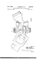
- FIG. 1 is a side view partially in section of the wideangle universal joint according to the present invention in a deflected or angular position;
- FIG. 2 is a view similar to that of FIG. 1 with the joint at the same deflected position but being rotated 90 degrees;
- FIG. 3 is a view similar to that of FIG. 1 showing a modification of the present joint wherein the flanged forks are bolted in an unsymmetrical position;
- FIG. 4 is a side view similar to that of FIG. 1 but showing a further modification of the double center yoke structure employed in interconnecting the outer yokes, and
- FIG. 5 is a similar view to that of FIG. 4 of the modification illustrated therein but partially in section and showing the joint rotated 90 degrees.
- the shafts to be connected by means of the universal joint have yokes 1 and 2 mounted on their ends thereof by splines or other suitable connection.
- Yoke 1 is provided with arms 3 and 4 with bores 5 therein in which is pivotally mounted a cross member or spider 6.
- Yoke 2 is similarly provided with arms 7 and 8 having bores 5 therein in which is pivotally mounted a cross member 9.
- the cross members are retained in their respective yokes by spring rings 10.
- cross member 6 The free ends or arms of cross member 6 are pivotally mounted in a fork member 11 having a flange 12 with a plurality of bolt holes therein.
- cross member 9 has its free ends pivotally mounted in a like fork member 14 having a flange 15 with corresponding bolt holes 16.
- the flanges are fastened together as shown in the drawing by means of bolts or screws 17 and, when fastened, form an annular gap 18 therebe tween.
- a centering plate 19 Slidably mounted within the annular gap or space 18 is a centering plate 19 which is provided with a pair of tubular bosses 20 and 21 extending axially from the oppossed faces of the centering plate 19.
- the bosses define sockets which are perpendicular from the centering plate.
- Yoke 1 carries a ball-head extension 22 which extends axially outwardly from a web 23 welded to the yoke as indicated at 24.
- yoke 2 is provided with a ballhead extension 25 extending axially from a web 26 welded to the yoke 2 at 27.
- annular space 18 slidably contained in the annular space 18 is a pair of flat annular rings 28 positioned on opposite sides of centering plate 19.
- the inner and outer diameters of the rings 28 are so related to the diameters of the annular space 18 and centering plate 19 that the space or gap is closed or sealed to the outside in all positions of displacement of the centering plate.
- the cylindrical or tubular sockets 20 and 21 on the centering plate 19 are provided with annular recesses 29 and 30 respectively at the bases thereof.
- the annular recesses enable the external or outer diameter of'the flange fork members 11 and 14 to be maintained within moderate limits for maximum deflection angles of the two shafts.
- the rings 28 are constructed as wearing members and will therefore prevent excessive wear of the fork members and of the centering plate.
- the centering plate and its associated rings can be readily replaced by removing the bolts 17 to disconnect the flanged fork members.
- universal joint according to the present invention comprises a relatively small number of components which are easy to fabricate.
- the fork members particularly the diameters of the flanges, and the yokes 1 and 2 may be so constructed that the maximum deflection angle of this joint can be increased considerably beyond the angle illustrated in the drawings.
- This universal joint can readily operate at a deflection angle of as much as 90 degrees while still providing a constant velocity transmission between the yokes of the joint.
- FIG. 3 there is illustrated a modification of the present universal joint wherein the fork members 11 and 14 are rotated 90 degrees with respect to each other and their flanges 12 and 15 then fastened together.
- the resulting center yoke structure comprising the fork members may be described as being unsymmetrical since the forks or lugs are displaced 90 degrees with respect to each other.
- FIG. 3 This modification of FIG. 3 is also illustrated with the wearing rings 28 being removed. It will be apparent that the present universal clutch will function equally well with or without the wearing rings, but that the wearing rings will close off the annular space from the exterior and thus prevent the entry of dirt to the cooperating surfaces of the flanges and centering plate.
- the center yoke structure is 'uidicated generally at 31 and comprises a body portion 32 from which two pairs of lugs 33 and 34 extends in opposite directions.
- the free ends of the cross members 6 and 9 are similarly pivotally connected in these lugs and retained in place by the spring rings 10.
- a central opening 35 is formed in the body portion and a centering member 36 is slidably mounted therein.
- the centering member is provided with opposed recesses 37 in which are positioned lubrication fittings 38 communicating with lubrication channels 39 to provide lubrication to a central bore 40.
- the bore 40 opens to the opposed faces of centering members 36 and slidably receives the ball-head extensions 22 and 25 as described above.
- the inner surface of the lugs 33 and 34 adjacent the opening 35 may be beveled as shown at 41 in order to permit greater freedom of movement of the yokes 1 and 2 during the operation of the universal joint.
- the present invention has disclosed a wide-angle constant velocity universal joint which is simple and compact in construction and can be readily serviced to replace the worn parts.
- the ball and socket connection between the shaft yokes and the centering member will insure that equal angles will be formed between the centering member and the respective shaft yokes in all angular positions of the shafts. This relationship will result in the transmission of constant velocity for all angular deflections of the shafts.
- This universal joint will permit angular shaft deflections up to about degrees. At this maximum deflection this constant velocity will still be transmitted.
- a pair of yokes with each yoke having a cross member therein means defining a pair of oppositely disposed fork members with each fork member being pivotally connected to one of said cross members, a centering member slidably mounted between said fork members and having opposed faces directed toward the respective yokes, means on the opposed faces of said centering member for defining axially extending cylindrical recesses thereon, and a ball-head extension on each of said yokes with said ball-heads being slidably received within said cylindrical recesses to provide an intermediate connection between said yokes through said centering member.
- each of said fork member having a flange with said flanges being fastened together.
- each of said tubular bosses having an annular recess at the base thereof.
Landscapes
- Engineering & Computer Science (AREA)
- General Engineering & Computer Science (AREA)
- Mechanical Engineering (AREA)
- Pivots And Pivotal Connections (AREA)
Description
WIDE-ANGLE CONSTANT VELOCITY UNIVERSAL JOINT Filed Jan- 15, 1968 Oct. 7, 1969 H. GEISTHOFF ETAL 5 Sheets8heet 1 INVENTORS HUBERT GEISTHOFF HEINRICH WELSHOF HUBERT GROSSE ENTRUP Oct. 7, 1969 Filed Jan. 15, 1968 H. GEISTHOFF ET 3,470,712
WIDE-ANGLE CONSTANT VELOCITY UNIVERSAL JOINT 5 Sheets-Sheet 2 ENVENTORS HUBERT GEISTHOFF HEINRICH WELSHOF HUBERT GROSS E- ENTRUP BY 77 Y. W
A RNEY Oct. 7, 1969 H. GEISTHOFF L 703 WIDE-ANGLE CONSTANT VELOCITY UNIVERSAL JOINT 5 Sheets-Sheet 3 Filed Jan. 15. 1968 A INVENTORS THOFF LSHOF -ENTRUP A'W/ORNEY CH T GROSSE JQ "4 5" 7 K Oct. 7, 1969 H. GEISTHOFF L 3 WIDE-ANGLE CONSTANT VELOCITY UNIVERSAL JOINT 5 Sheets-Sheet 4 Filed Jan. 15, 1968 INVENTORS HUBERT GEISTHOFF HEINRICH WELSHOF HUBERT GROSSE- ENTRUP 06E. 7, 1969" H. GEISTHOFF ETAL 3,470,712
WIDE-ANGLE CONSTANT VELOCITY UNIVERSAL JOINT Filed Jan. 15, 1968 5 Sheets-Sheet 5 HUBERT GEIISTHOFF HEINRICH .WELSHOF HUBERT GROSSE-ENTRUP v l, f I
a m a Int. Cl. F16d 3/34 US. Cl. 64-21 Claims ABSTRACT OF THE DISCLOSURE A universal joint wherein a double Hookes joint has the cross members pivotally connected to flanged fork members whose flanges are fastened together so as to slidably enclose a centering plate having opposed cylindrical recesses in which are slidably received ball head extensions mounted on the respective yokes of the double joint.
The present invention relates to a wide angle universal joint comprising a double Hookes joint, more particularly, to the intermediate connection between the yokes of the double joint.
A well-known form of a universal joint is the Hookes joint or, as it is sometimes known, the Garden joint. 'In order to form a constant velocity joint or coupling, two of said joints are connected through an intermediate shaft or connection. However, the generally used form of a double Hookes joint has the disadvantage that when the two coupled shafts are at relatively large angles of deflection, the coupling is unable to transmit a constant velocity. Many forms of wide-angle universal joints have been devised in attempts to transmit constant velocity at the widest angles of deflection between the shafts coming into the joint.
One such form of a universal joint comprises a double Hookes joint in which the two cross members are centered with respect to each other by an interposed ball. However, it has been found that at relatively large angles of deflection this joint will not transmit constant velocity. In a modification of a double Hookes joint the two cross members are relatively centered by two balls and a centering plate. While this joint is relatively accurate in transmitting a velocity ratio of 1 this joint is not capable of permitting large deflection angles between the coupled shafts.
It is therefore the principal object of the present invention to provide a novel and improved wide-angle constant velocity universal joint.
It is another object of the present invention to provide a universal joint having an improved intermediate connection between a double Hookes joint so that the joint will transmit a constant velocity at wide angles of deflection.
It is a further object of the present invention to provide a wide-angle constant velocity universal joint which is simple in construction so as to be capable of a long operating life with a minimum of maintenance.
The objects of the persent invention are achieved and the disadvantages of the prior art are eliminated by the universal joint according to the present invention. In one embodiment of this universal joint the shafts which are to be connected each have a yoke at their cooperating ends with each being provided with a cross member as known in the art. A pair of flanged forks have their flanges bolted together and define an annular gap between the bolted forks. A centering plate is slidably mounted within the annular gap and a pair of flat annular rings are disposed United States PatentO 3,470,712 Patented Oct. 7, 1969 c ICC within the gap on both sides of the centering plate. On the opposed faces of the centering plate there are provided axially extending cylindrical recesses which slidably re ceive ball-head extensions attached to each of the shaft yokes.
The wide-ang1e universal joint according to the present invention will transmit a constant velocity up to maximum deflection angles of to degrees. The relatively simple design of this universal joint greatly facilitates its fabrication and provides for relatively inexpensive manufacturing cost. The joint is compact and can be readily accomodated in'a wide variety of structures. Servicing of the joint is is also facilitated since the worn parts can be readily replaced. In addition, the construction of this joint virtually eliminates any malfunctioning during operation even at wide angles of deflection.
Other objects and advantages of the present invention will be apparent upon reference to accompanying description when taken in conjunction with the following drawings wherein:
FIG. 1 is a side view partially in section of the wideangle universal joint according to the present invention in a deflected or angular position;
FIG. 2 is a view similar to that of FIG. 1 with the joint at the same deflected position but being rotated 90 degrees;
FIG. 3 is a view similar to that of FIG. 1 showing a modification of the present joint wherein the flanged forks are bolted in an unsymmetrical position;
FIG. 4 is a side view similar to that of FIG. 1 but showing a further modification of the double center yoke structure employed in interconnecting the outer yokes, and
FIG. 5 is a similar view to that of FIG. 4 of the modification illustrated therein but partially in section and showing the joint rotated 90 degrees.
Proceeding next to the drawings: wherein like reference symbols indicate the same parts throughout the various views a specific embodiment and several modifications of the present invention will be described in detail.
As may be seen in FIG. 1 the shafts to be connected by means of the universal joint have yokes 1 and 2 mounted on their ends thereof by splines or other suitable connection. Yoke 1 is provided with arms 3 and 4 with bores 5 therein in which is pivotally mounted a cross member or spider 6.
Yoke 2 is similarly provided with arms 7 and 8 having bores 5 therein in which is pivotally mounted a cross member 9. The cross members are retained in their respective yokes by spring rings 10.
The free ends or arms of cross member 6 are pivotally mounted in a fork member 11 having a flange 12 with a plurality of bolt holes therein. In a similar manner the cross member 9 has its free ends pivotally mounted in a like fork member 14 having a flange 15 with corresponding bolt holes 16. The flanges are fastened together as shown in the drawing by means of bolts or screws 17 and, when fastened, form an annular gap 18 therebe tween.
Slidably mounted within the annular gap or space 18 is a centering plate 19 which is provided with a pair of tubular bosses 20 and 21 extending axially from the oppossed faces of the centering plate 19. The bosses define sockets which are perpendicular from the centering plate.
Yoke 1 carries a ball-head extension 22 which extends axially outwardly from a web 23 welded to the yoke as indicated at 24. Similarly yoke 2 is provided with a ballhead extension 25 extending axially from a web 26 welded to the yoke 2 at 27.
Also, slidably contained in the annular space 18 is a pair of flat annular rings 28 positioned on opposite sides of centering plate 19. The inner and outer diameters of the rings 28 are so related to the diameters of the annular space 18 and centering plate 19 that the space or gap is closed or sealed to the outside in all positions of displacement of the centering plate.
The cylindrical or tubular sockets 20 and 21 on the centering plate 19 are provided with annular recesses 29 and 30 respectively at the bases thereof. The annular recesses enable the external or outer diameter of'the flange fork members 11 and 14 to be maintained within moderate limits for maximum deflection angles of the two shafts.
It is pointed out that the ball-headed extensions 22 and 25 are slidably received in the cylindrical sockets 20 and 21. The web members 23 and 26 which carry the ballheaded extensions are welded on the outer ends of yokes 1 and 2. As a result of this construction the joint can be assembled from a minimum of separate parts.
It will be apparent that during the operation of this universal joint when power is transmitted from one shaft to the other the twin fork members 11 and 14 will always be forced into a center position with respect to the shaft yokes 1 and 2. The ball-headed extensions on the yokes 1 and 2 slidably cooperating with the cylindrical sockets on the centering plate, will insure that the flanges 12 and 15 of the fork members will always be exactly bisect the angle between yokes 1 and 2. This will insure constant velocity transmission regardless of the deflection angle between the two shafts. During the rotation of these shafts, the centering plate will slide back and forth in the annular gap between the flanges of the fork member. At the same time, the rings 28 will form a seal between this gap and the exterior.
The rings 28 are constructed as wearing members and will therefore prevent excessive wear of the fork members and of the centering plate. The centering plate and its associated rings can be readily replaced by removing the bolts 17 to disconnect the flanged fork members.
It is apparent that universal joint according to the present invention comprises a relatively small number of components which are easy to fabricate.
According to the teachings of the present invention the fork members, particularly the diameters of the flanges, and the yokes 1 and 2 may be so constructed that the maximum deflection angle of this joint can be increased considerably beyond the angle illustrated in the drawings. This universal joint can readily operate at a deflection angle of as much as 90 degrees while still providing a constant velocity transmission between the yokes of the joint.
In FIG. 3 there is illustrated a modification of the present universal joint wherein the fork members 11 and 14 are rotated 90 degrees with respect to each other and their flanges 12 and 15 then fastened together. The resulting center yoke structure comprising the fork members may be described as being unsymmetrical since the forks or lugs are displaced 90 degrees with respect to each other.
This modification of FIG. 3 is also illustrated with the wearing rings 28 being removed. It will be apparent that the present universal clutch will function equally well with or without the wearing rings, but that the wearing rings will close off the annular space from the exterior and thus prevent the entry of dirt to the cooperating surfaces of the flanges and centering plate.
In FIGS. 4 and there is illustrated a further modification of the present invention wherein the center yoke structure is comprised of a unitary member instead of the flanged fork members of the embodiment as described above. In this modification the center yoke structure is 'uidicated generally at 31 and comprises a body portion 32 from which two pairs of lugs 33 and 34 extends in opposite directions. The free ends of the cross members 6 and 9 are similarly pivotally connected in these lugs and retained in place by the spring rings 10.
A central opening 35 is formed in the body portion and a centering member 36 is slidably mounted therein. The centering member is provided with opposed recesses 37 in which are positioned lubrication fittings 38 communicating with lubrication channels 39 to provide lubrication to a central bore 40. The bore 40 opens to the opposed faces of centering members 36 and slidably receives the ball-head extensions 22 and 25 as described above.
It will be apparent that the opposed faces of centering member 36 slide over the faces of the opening 35 in a manner analogous to that of centering plate 19 sliding in the annular gap 18 of the embodiment illustrated in FIG. 1. The universal joint of FIGS. 4 and 5, therefore, functions in the same manner as the embodiment of the universal joint described above.
The inner surface of the lugs 33 and 34 adjacent the opening 35 may be beveled as shown at 41 in order to permit greater freedom of movement of the yokes 1 and 2 during the operation of the universal joint.
Thus it can be seen that the present invention has disclosed a wide-angle constant velocity universal joint which is simple and compact in construction and can be readily serviced to replace the worn parts. The ball and socket connection between the shaft yokes and the centering member will insure that equal angles will be formed between the centering member and the respective shaft yokes in all angular positions of the shafts. This relationship will result in the transmission of constant velocity for all angular deflections of the shafts. This universal joint will permit angular shaft deflections up to about degrees. At this maximum deflection this constant velocity will still be transmitted.
It will be understood that this invention is suspectible to modification in order to adapt it to different usages and conditions and, accordingly, it is desired to comprehend such modifications within this invention as may fall within the scope of the appended claims.
What is claimed is:
1. In a universal joint, a pair of yokes with each yoke having a cross member therein, means defining a pair of oppositely disposed fork members with each fork member being pivotally connected to one of said cross members, a centering member slidably mounted between said fork members and having opposed faces directed toward the respective yokes, means on the opposed faces of said centering member for defining axially extending cylindrical recesses thereon, and a ball-head extension on each of said yokes with said ball-heads being slidably received within said cylindrical recesses to provide an intermediate connection between said yokes through said centering member.
2. In a universal joint as claimed in claim 1, with said fork members being fastened together and means on said fork members for defining an annular space therebetween, said centering member being positioned in said annular space.
3. In a universal joint as claimed in claim 1 with each of said fork member having a flange with said flanges being fastened together.
4. In a universal joint as claimed in claim 1 with said recess defining means comprising a tubular boss extending perpendicularly to said centering member.
5. In a universal joint as claimed in claim 2, and further comprising a pair of flat annular rings within said annular space on both sides of said centering member, the inner and outer diameters of said rings being such that said annular space is closed from the exterior in all positions of said centering member.
6. In a universal joint as claimed in claim 4 with each of said tubular bosses having an annular recess at the base thereof.
7. In a universal joint as claimed in claim 1 with said ball head extensions each comprising a web attached to the outer end of its respective yoke.
8. In a universal joint as claimed in claim 3 with said References Cited Eagggi tfgriafiegitlfigs being symmetrically disposed with UNITED STATES PATENTS 9. In a universal joint as claimed in claim 1 with said 724068 3/1903 Wllhams 64 2 centering member having a bore therethrough to define 5 1,979,768 11/1934 Pearce 642 said opposed cylindrical recesses so that said recesses 2,755,641 7/1956 Dunn are in communication with each other. FOREIGN PATENTS 10. In a universal joint as claimed in claim 9 and further comprising means on said centering member for 1265194 5/1961 France lubricating said bore between said slidably received ball 10 HALL c COB Primary Examiner head extensions.
Applications Claiming Priority (1)
| Application Number | Priority Date | Filing Date | Title |
|---|---|---|---|
| US69776168A | 1968-01-15 | 1968-01-15 |
Publications (1)
| Publication Number | Publication Date |
|---|---|
| US3470712A true US3470712A (en) | 1969-10-07 |
Family
ID=24802428
Family Applications (1)
| Application Number | Title | Priority Date | Filing Date |
|---|---|---|---|
| US697761A Expired - Lifetime US3470712A (en) | 1968-01-15 | 1968-01-15 | Wide-angle constant velocity universal joint |
Country Status (1)
| Country | Link |
|---|---|
| US (1) | US3470712A (en) |
Cited By (20)
| Publication number | Priority date | Publication date | Assignee | Title |
|---|---|---|---|---|
| US4112709A (en) * | 1975-09-25 | 1978-09-12 | Uni-Cardan Ag | Double universal joint |
| JPS53134144A (en) * | 1977-04-27 | 1978-11-22 | Koyo Seiko Co Ltd | Universal joint |
| FR2392273A1 (en) * | 1977-05-26 | 1978-12-22 | Bondioli Edi | HOMOCINETIC JOINT FOR TRANSMISSION SHAFTS FOR AGRICULTURAL MACHINES OR OTHER APPLICATIONS |
| US4257243A (en) * | 1978-01-21 | 1981-03-24 | Jean Walterschied Gmbh | Homokinetic double joint for wide bending angles |
| JPS56168626U (en) * | 1981-02-02 | 1981-12-12 | ||
| US4464136A (en) * | 1981-10-29 | 1984-08-07 | Jean Walterscheid Gmbh | Lubricated wide angle universal joint |
| US4490125A (en) * | 1981-09-25 | 1984-12-25 | Jean Walterscheid Gmbh | Lubricated wide angle joint |
| US4650439A (en) * | 1984-12-10 | 1987-03-17 | Weasler Engineering, Inc. | Centering apparatus for constant velocity universal joint |
| US5419740A (en) * | 1992-03-16 | 1995-05-30 | Toyota Jidosha Kabushiki Kaisha | Constant velocity joint having centering disk bearing eccentric socket |
| US6024645A (en) * | 1996-04-05 | 2000-02-15 | Nsk Ltd. | Double cardan type constant velocity joint |
| EP1253338A1 (en) | 2001-04-26 | 2002-10-30 | GKN Walterscheid GmbH | Centred double universal joint |
| US6616536B2 (en) * | 2001-07-20 | 2003-09-09 | Gkn Walterscheid Gmbh | Centered double universal joint |
| US20040077411A1 (en) * | 2002-08-27 | 2004-04-22 | Dupuie Bradley A. | Constant velocity joint assembly |
| US7128653B1 (en) | 2003-04-01 | 2006-10-31 | Torque-Traction Technologies Llc | Double Cardan centering mechanism |
| US20060276249A1 (en) * | 2005-05-14 | 2006-12-07 | Manfred Heintschel | Steering shaft |
| WO2008151223A1 (en) * | 2007-06-05 | 2008-12-11 | Weasler Engineering, Inc. | Universal joint with improved ball lubrication |
| DE10135347B4 (en) * | 2001-07-20 | 2012-06-14 | Gkn Walterscheid Gmbh | Centered double universal joint |
| US8915788B2 (en) | 2012-04-29 | 2014-12-23 | Cathedral Energy Services Ltd. | Universal joint for a downhole drilling motor |
| US20160281791A1 (en) * | 2015-03-26 | 2016-09-29 | Roop Automotives Limited | Double cardan yoke assembly |
| US20170292571A1 (en) * | 2016-04-06 | 2017-10-12 | Mando Corporation | Wide angle joint |
Citations (4)
| Publication number | Priority date | Publication date | Assignee | Title |
|---|---|---|---|---|
| US724068A (en) * | 1902-09-17 | 1903-03-31 | Waterbury Tool Co | Double universal joint. |
| US1979768A (en) * | 1933-07-24 | 1934-11-06 | John W B Pearce | Double universal joint |
| US2755641A (en) * | 1953-09-21 | 1956-07-24 | Chrysler Corp | Universal joint |
| FR1265194A (en) * | 1960-05-12 | 1961-06-30 | Renault | Constant velocity joint |
-
1968
- 1968-01-15 US US697761A patent/US3470712A/en not_active Expired - Lifetime
Patent Citations (4)
| Publication number | Priority date | Publication date | Assignee | Title |
|---|---|---|---|---|
| US724068A (en) * | 1902-09-17 | 1903-03-31 | Waterbury Tool Co | Double universal joint. |
| US1979768A (en) * | 1933-07-24 | 1934-11-06 | John W B Pearce | Double universal joint |
| US2755641A (en) * | 1953-09-21 | 1956-07-24 | Chrysler Corp | Universal joint |
| FR1265194A (en) * | 1960-05-12 | 1961-06-30 | Renault | Constant velocity joint |
Cited By (29)
| Publication number | Priority date | Publication date | Assignee | Title |
|---|---|---|---|---|
| US4112709A (en) * | 1975-09-25 | 1978-09-12 | Uni-Cardan Ag | Double universal joint |
| JPS53134144A (en) * | 1977-04-27 | 1978-11-22 | Koyo Seiko Co Ltd | Universal joint |
| JPS5619504B2 (en) * | 1977-04-27 | 1981-05-08 | ||
| FR2392273A1 (en) * | 1977-05-26 | 1978-12-22 | Bondioli Edi | HOMOCINETIC JOINT FOR TRANSMISSION SHAFTS FOR AGRICULTURAL MACHINES OR OTHER APPLICATIONS |
| US4257243A (en) * | 1978-01-21 | 1981-03-24 | Jean Walterschied Gmbh | Homokinetic double joint for wide bending angles |
| JPS56168626U (en) * | 1981-02-02 | 1981-12-12 | ||
| US4490125A (en) * | 1981-09-25 | 1984-12-25 | Jean Walterscheid Gmbh | Lubricated wide angle joint |
| US4464136A (en) * | 1981-10-29 | 1984-08-07 | Jean Walterscheid Gmbh | Lubricated wide angle universal joint |
| US4650439A (en) * | 1984-12-10 | 1987-03-17 | Weasler Engineering, Inc. | Centering apparatus for constant velocity universal joint |
| US5419740A (en) * | 1992-03-16 | 1995-05-30 | Toyota Jidosha Kabushiki Kaisha | Constant velocity joint having centering disk bearing eccentric socket |
| US6024645A (en) * | 1996-04-05 | 2000-02-15 | Nsk Ltd. | Double cardan type constant velocity joint |
| US6719636B2 (en) | 2001-04-26 | 2004-04-13 | Gkn Walterscheid Gmbh | Centered double universal joint |
| AU755323B2 (en) * | 2001-04-26 | 2002-12-12 | Gkn Walterscheid Gmbh | Centred double universal joint |
| EP1253338A1 (en) | 2001-04-26 | 2002-10-30 | GKN Walterscheid GmbH | Centred double universal joint |
| US6616536B2 (en) * | 2001-07-20 | 2003-09-09 | Gkn Walterscheid Gmbh | Centered double universal joint |
| DE10135347B4 (en) * | 2001-07-20 | 2012-06-14 | Gkn Walterscheid Gmbh | Centered double universal joint |
| US6840864B2 (en) | 2002-08-27 | 2005-01-11 | Delphi Technologies, Inc. | Constant velocity joint assembly |
| US20040077411A1 (en) * | 2002-08-27 | 2004-04-22 | Dupuie Bradley A. | Constant velocity joint assembly |
| US7128653B1 (en) | 2003-04-01 | 2006-10-31 | Torque-Traction Technologies Llc | Double Cardan centering mechanism |
| US20060276249A1 (en) * | 2005-05-14 | 2006-12-07 | Manfred Heintschel | Steering shaft |
| WO2008151223A1 (en) * | 2007-06-05 | 2008-12-11 | Weasler Engineering, Inc. | Universal joint with improved ball lubrication |
| US8246473B2 (en) | 2007-06-05 | 2012-08-21 | Weasler Engineering, Inc. | Universal joint with improved ball lubrication |
| US8915788B2 (en) | 2012-04-29 | 2014-12-23 | Cathedral Energy Services Ltd. | Universal joint for a downhole drilling motor |
| US20160281791A1 (en) * | 2015-03-26 | 2016-09-29 | Roop Automotives Limited | Double cardan yoke assembly |
| US10145422B2 (en) * | 2015-03-26 | 2018-12-04 | Roop Automotives Limited | Double cardan yoke joint with a single weld |
| US20170292571A1 (en) * | 2016-04-06 | 2017-10-12 | Mando Corporation | Wide angle joint |
| KR20170114733A (en) * | 2016-04-06 | 2017-10-16 | 주식회사 만도 | Wide Angle Joint |
| US10883546B2 (en) * | 2016-04-06 | 2021-01-05 | Mando Corporation | Wide angle joint |
| KR102531422B1 (en) | 2016-04-06 | 2023-05-12 | 에이치엘만도 주식회사 | Wide Angle Joint |
Similar Documents
| Publication | Publication Date | Title |
|---|---|---|
| US3470712A (en) | Wide-angle constant velocity universal joint | |
| US2813409A (en) | Universal coupling | |
| US3306077A (en) | Universal joints | |
| US2067286A (en) | Double universal joint | |
| US3838759A (en) | Jaw clutch for multi-speed gear trains or the like | |
| CA1193874A (en) | Piloted flexible coupling | |
| US3287934A (en) | Universal joints and couplings | |
| US1820750A (en) | Flexible coupling | |
| US3575015A (en) | Splined shaft connection | |
| US4352276A (en) | Constant velocity universal joint with improved centering device and boot seal | |
| US3429144A (en) | Center bearing double cardan joint | |
| US2979925A (en) | Flexible shaft couplings | |
| US2332859A (en) | Shaft coupling | |
| US4436515A (en) | Articulation device having a double universal joint and a ball joint unit | |
| US3461688A (en) | Constant velocity universal joint | |
| US1582997A (en) | Flexible coupling | |
| CN107687481A (en) | Universal coupling | |
| US3279216A (en) | Misalignment coupling | |
| US4136532A (en) | Drive shaft | |
| US2462574A (en) | Joint for shafts | |
| US2142784A (en) | Universal coupling | |
| US4195495A (en) | Universal joint | |
| US2476473A (en) | Universal coupling | |
| US3106076A (en) | Universal joints | |
| US4126018A (en) | Apparatus for interconnecting rotary shafts |