US3327190A - Electronic timepiece - Google Patents
Electronic timepiece Download PDFInfo
- Publication number
- US3327190A US3327190A US414702A US41470264A US3327190A US 3327190 A US3327190 A US 3327190A US 414702 A US414702 A US 414702A US 41470264 A US41470264 A US 41470264A US 3327190 A US3327190 A US 3327190A
- Authority
- US
- United States
- Prior art keywords
- coil
- coil combination
- coils
- magnet
- combination means
- Prior art date
- Legal status (The legal status is an assumption and is not a legal conclusion. Google has not performed a legal analysis and makes no representation as to the accuracy of the status listed.)
- Expired - Lifetime
Links
Images


Classifications
-
- G—PHYSICS
- G04—HOROLOGY
- G04C—ELECTROMECHANICAL CLOCKS OR WATCHES
- G04C3/00—Electromechanical clocks or watches independent of other time-pieces and in which the movement is maintained by electric means
- G04C3/04—Electromechanical clocks or watches independent of other time-pieces and in which the movement is maintained by electric means wherein movement is regulated by a balance
- G04C3/06—Electromechanical clocks or watches independent of other time-pieces and in which the movement is maintained by electric means wherein movement is regulated by a balance using electromagnetic coupling between electric power source and balance
- G04C3/065—Electromechanical clocks or watches independent of other time-pieces and in which the movement is maintained by electric means wherein movement is regulated by a balance using electromagnetic coupling between electric power source and balance the balance controlling gear-train by means of static switches, e.g. transistor circuits
- G04C3/066—Constructional details, e.g. disposition of coils
-
- G—PHYSICS
- G04—HOROLOGY
- G04C—ELECTROMECHANICAL CLOCKS OR WATCHES
- G04C3/00—Electromechanical clocks or watches independent of other time-pieces and in which the movement is maintained by electric means
- G04C3/04—Electromechanical clocks or watches independent of other time-pieces and in which the movement is maintained by electric means wherein movement is regulated by a balance
- G04C3/06—Electromechanical clocks or watches independent of other time-pieces and in which the movement is maintained by electric means wherein movement is regulated by a balance using electromagnetic coupling between electric power source and balance
- G04C3/065—Electromechanical clocks or watches independent of other time-pieces and in which the movement is maintained by electric means wherein movement is regulated by a balance using electromagnetic coupling between electric power source and balance the balance controlling gear-train by means of static switches, e.g. transistor circuits
Definitions
- This invention relates to electronic clocks and more particularly it relates to electronic driving means for an oscillating member which may also be used to drive the escapement mechanisms of a watch or clock.
- the above circuits are also temperature sensitive and accurate time keeping is not possible over wide temperature fluctuations.
- Some of the transistors used in the circuits have amplification factors which vary greatly with temperature fluctuations. If the circuit is designed in such a manner that low battery voltages of about 1 volt are sutficient to open the transistor completely, it is found that the required magnets and their associated coils must of necessity be very large. Consequently the timepieces will be much heavier and will require more power for their operation than would be necessary if the excitation developed would need to open the transistor only when the full operating voltage is applied.
- the voltage for controlling a transistor can be varied only within the limits determined by the dimensions of the magnets and coils.
- the transistor can be modulated either at a low operating voltage, or at a higher voltage.
- the elfort has generally been to make the excitation so powerful that the transistor will 'be modulated even by a low operating voltage. This necessitates a breaking of the oscillating movement, which in turn increases the power that has to be taken from the battery. As long as the battery voltage remains high, a portion of the power that is delivered to the driving coil will be dissipated and the normal energy balance will not be established until the battery voltage has dropped to a certain level.
- Such a damping of the operating mechanism has also the disadvantage of becoming effective only after an oscillating movement of As soon as the oscillating movement becomes less than 180, such a damping means will cease to operate.
- the battery life has therefore been shortened sufliciently so that the available voltage will always be sufficient to cause the oscillating movement to exceed 180.
- a small battery would be able to operate an electronic timepiece for several years, the time for renewing it is generally established at about one year. Only in this manner can the mechanism be regulated during that period of time. As a result not more than 6 of the total life of the battery has been used.
- This invention relates to an electronic mechanism for driving an oscillating member such as a balance wheel of a timepiece by means of a transistor circuit.
- Magnets are positioned on the oscillating member and stationary coils are positioned in the mechanism in such a manner that the magnets carried by the oscillating member will move in close proximity to the coils to generate an impulse in the exciter coils which will deliver a driving impulse over the transistor circuit to the collector or emitter circuit.
- the magnets are secured on a thin non-magnetic plate which is fixed to rotate with the balance wheel and the magnets are positioned axially on the plate in spaced relationship to each other with opposite poles being secured to the plate.
- a coil combination consisting of an exriter coil and a driver coil is placed above the magnets and a similar coil combination is placed below the magnets, and suitable iron discs or plates are fixed to rotate with the oscillating member and enclose the magnets and coils therebetween.
- the spacing and sizes of the coils and magnets relative to one another is such that a triply strengthened impulse will be produced for both the excitation and the driving impulses by the simultaneous: (l) repulsion of a first magnet from the first coil combination; (2) repulsion of the second magnet from the second coil combination; and (3) attraction of the first magnet to said second coil combination or attraction of the second magnet to said first coil combination.
- the oscillating member or balance wheel can be made very small as well as the magnets, which will greatly reduce the weight of the balance wheel along with the height and depth thereof.
- An object of this invention is to produce an electronically operated driving mechanism for a timepiece which is extremely compact, efiicient over wide temperature ranges and economical to produce.
- a further object of this invention is to produce an electronically operated timepiece which will operate accurately over a wide fluctuation in voltage from a power source such as a battery and with a more complete utilization thereof.
- a further object of this invention is to produce an electronically operated timepiece which is compact and also has a high energy balance to actuate a spring winding mechanism.
- FIGURE 1 is a side view of the electronic driving mechanism of this invention
- FIGURE 2 is a plan view of FIGURE 1;
- FIGURE 3 is a diagram showing the relationship of the excitation impulse to the driving impulse during the time in which the magnets move into the coils;
- FIGURE 4 is a diagram of a circuit used in this invention.
- FIGURE is a side view of a second embodiment of this invention with magnets on the upper and lower plates in addition to those on the central plate;
- FIGURE 6 is a diagrammatic view showing the driving means of this invention operatively connected to a spring winding mechanism
- FIGURE 7 shows a perspective view of the coil support structure.
- FIGURES 1 and 2 show a first embodiment of the invention.
- the oscillating member shown is of the balance wheel variety comprising an axis 1 which is pivotally mounted in a bearing means In secured in a frame and to which axis is attached a plate 2 made of non-magnetic material and having the shape shown in FIGURE 2.
- a plate 2 made of non-magnetic material and having the shape shown in FIGURE 2.
- magnets 5 and 6 positioned in spaced relationship to each other and are secured to the plate 2 with their individual axes parallel to axis 1.
- Magnet 5 has its south pole facing upwardly as viewed in FIGURE 1 and magnet 6 has the north pole facing upwardly.
- suitable corresponding counterweights 13 and 14 positioned and secured to plate 2 as shown.
- a coil combination 7 consisting of an exciter coil and a driver coil is positioned in a plane parallel to and above the plate 2 with the magnets thereon.
- a similar coil combination 8 consisting of an exciter coil and a driver coil is positioned in a plane parallel to and below the plate 2. Both coil combinations 7 and 8 are supported in coil support members 10 and 11, respectively, which are suitably secured to a support block means 9.
- the dimensions of the wing segment 12 of plate 2 are determined by the required diameters of the magnets and their distance from each other. With a magnet diameter of about 5 mm. the total width of the segment need be only 20 mm.
- the non-magnetic counterbalancing weights 13 and 14 are secured to a similarly shaped segment 15 of plate 2.
- the plates 2, 3, and 4 may be provided with notches or recesses to make them lighter.
- a magnet diameter of 3 mm. the width of the wing segment 12 need be only 9 mm. wide, and with a magnet diameter of 1.5 mm. the wing segment correspondingly need be only 5 mm. wide.
- the weight of the balance wheel mm. in diameter according to this invention would be about 2 g. while in prior art constructions, the weight is generally at least 810 grams.
- FIGURE 3 shows the relation of the excitation impulse to the driver impulse during the time while the magnets move into the coils.
- a sinusoidal impulse of a certain voltage will be produced whose height must always be less than the maximum excitation voltage and current for complete opening of the transistor.
- These values for the modulation of the transistor are represented by the dotted line (a).
- the excitation (e) is three times higher than the driving voltage (d), as rep resented by the curves on FIGURE 3.
- the transistor In this system, even if there is a loweringof the battery voltage, the transistor will always be completely opened. In the driver coil, only such currents can flow as are permitted by the ohmic resistance of the coil in relation to the voltage of the battery. In the normal circuit the collector voltage is directly dependent on the battery voltage so that the current will diminish in linear relation to the battery voltage. In the circuit of this invention, however, the collector voltage remains the same during either high or low driver voltage because the transistor is always completely open. This will produce a more uniform amplitude throughout a wide voltage range.
- This invention also has another advantage for driving a timepiece in that the prior art driving systems usually require amplitude swings of at least to to put the timepiece into operation. With this invention a swing of only a few degrees is suflicient to start the mechanism running normally. Even an electric connection of the transistor base through a resistor of the negative terminal of the battery will suflice completely so that by merely pressing a button, the mechanical oscillator can be started running and will be in normal operation after a few swings. Under all operating conditions, even with a lowering of the battery voltage, the amplitude of oscillation will be far beyond 180. No braking or damping of the balance wheel is required.
- the two coil combinations of this invention are connected together as shown in FIGURE 4 and this arrangement has the advantage of permitting a small capacitor 2% to be connected between the two driver coils 7d and 8d with the other terminal of the capacitor being connected to the transistor base 22 which is especially helpful in starting.
- the collector voltage will become negative and this negative voltage will be fed back through the capacitor to the transistor base.
- FIGURE 4 also shows the exciter coi-l 7c of coil combination 7 and the exciter coil 8e of coil combination 8 connected in series between the emitter 26 and base 22.
- the driver coils 7d and 8d are connected in series between the battery 24 and the collector 28.
- FIGURE 5 shows a second modification of this invention wherein like numbers are used to identify similar parts.
- magnets 5 and 6 may be advantageous to use very small flat magnets in both the middle segment and the upper and lower segments instead of the magnets 5 and 6 with the upper and lower closure plates 3 and 4'. In this manner it will be possible to use magnets of 1 mm. or less in diameter, and if very flat magnets are used, the height of the entire balance wheel structure can be reduced. The only requirement is that the dimensions of the magnets and the coils should be kept in proportion in such a manner that the exciter impulse and the driving impulse will be strengthened threefold.
- the arrangement in FIGURE 5 may include magnets 30 and 32 which are positioned on the plate 2 similar to the arrangement shown in FIGURE 2.
- Magnet 34 is positioned or secured on plate 36 and is axially aligned with magnet 30 and magnet 38 is positioned and secured to plate 40 and is axially aligned with magnet 32.
- the plates 36 and 38 may be non-ferrous and may have the shape similar to that shown in FIGURE 2.
- the driving mechanism of this invention By the driving mechanism of this invention, a very high energy balance is obtained which may be used for winding up a spring housing, as shown diagrammatically in FIGURE 6.
- the driving mechanism generally designated 42 which may also include known ratchet systems for driving the shaft 44 extending therefrom and which shaft is rotatably mounted in a bearing 46.
- One plate 48 of a friction clutch is fixed to rotate with the shaft 44.
- a second plate 50 of the friction clutch is axially slidable on shaft 52 and fixed to rotate therewith.
- the shaft 52 is operatively connected to a spring means in housing 54 to tension the spring means therein.
- the spring means therein is operatively connected to a known time indicating mechanism 56.
- the clutch coupling is used to maintain the spring means in the housing in the wound or tensioned state.
- a suitable lever support 58 is rotatably mounted on shaft 52 and is fixed to the frame of the mechanism.
- Lever 60 is pivotally mounted on coupling 58 and has a cam member 62 thereon.
- a spring member 64 secured to one end of lever and is fixed to the frame to urge cam member 62 into engagement with slidable clutch plate 50 and push it into engagement with the other friction plate 48 to thereby effect frictional driving engagement of the plates wtih each other so that driving mechanism 42 will wind the spring means in housing 54.
- a rotatable member 66 rotates to pull the other end of lever 66 via wire means 67 and thereby disengage clutch plate 50 from plate 48 and prevent overwinding of spring in the housing 54.
- a standard slip clutch arrangement (not shown) may also be used to effect the clutch coupling.
- FIGURE 7 shows a perspective view of the coil support structure 9 and how the coil combinations 7 and 8 are positioned in two planes and how they are vertically offset from each other. A convenient way of connecting the coils in circuit is also shown.
- the coil support 9 has four pins 68 passing therethrough centrally of the coils and pass through coil support 10 and are exposed in a well 70 thereon.
- the ends of the coil combination 7 (shown as a single strand) can be then conveniently soldered to the appropriate pin 68 and connected in circuit as shown in FIGURE 4.
- the mounting and connecting of coil combination 8 on support 11 is similar although not shown in the drawings.
- the driver coil of each combination may be concentrically positioned inside the exciter coil.
- a balance wheel having shaft means pivotally supported for oscillation of the balance wheel on a given axis and having first and second permanent magnet means thereon with the magnetic axes of said magnet means being radially spaced from and parallel to said axis of said wheel and circumferentially spaced from each other and poled in respectively opposite directions, first and second stationary coil combination means in spaced parallel relationship to each other with the axes of said coil combination means being parallel to and radially spaced from said axis of said heel and circumferentially spaced from each other, said first and second coil combination means being adapted to be influenced by the movement of said magnet means relative thereto, each said coil combination means comprising an exciter coil and a driver coil concentric therewith, a transistor having a base, an emitter, and a collector, a source of voltage, first circuit means connecting said driver coils and said source of voltage in series between said emitter and said collector, second circuit means connecting said exciter coils in series between said emitter and said base, the spacing of
- said balance wheel comprises middle, upper, and lower plate means which are in spaced parallel relationship to one another and are secured to said shaft means of said balance wheel with said middle plate means being made of non-magnetic material and said upper and lower plate means being made of magnetic material and with all said plate means being similarly dimensioned and axially aligned on said shaft means of said wheel, said first and second magnet means being secured on said middle plate means with opposite poles secured thereto, said first and second coil combination means being axially displaced from each other on opposite sides of the plane of said middle plate, said middle plate means with the magnet means thereon being adapted to oscillate in the axial space between said first and second coil combination means with said upper and lower plate means forming closure plates about said coil combination means.
- the timepiece as claimed in claim 2 further comprising a capacitor having one end connected to said base of said transistor, said series connected driver coils having a junction therebetween to which the other end of said capacitor is connected.
- the timepiece as claimed in claim 1 further comprising a capacitor having one end connected to said base of said transistor, said series connected driver coils having a junction therebetween to which the other end of said capacitor is connected.
- the timepiece as claimed in claim 1 further comprising spring means, coupling means operatively connected to said balance wheel and said spring means for tensioning said spring means by said balance wheel, said coupling means comprising; clutch means having a first plate member operatively connected with said balance wheel and a second plate member operatively connected with said spring means, and means operatively connected with said spring means to bring said first and second plate members into operative engagement upon the running down of said spring means and to disengage said plate members upon the full tensioning of said spring means.
- the timepiece as claimed in claim 1 further comprising support means for said first and second coil combination means, said support means comprising; support block means, first and second coil holder means secured to said block means and being parallel to each other and offset from each other for supporting said first and second coil combination means respectively, said circuit means comprising metal pins driven through said support block means and extending into said coil holder means in order to enable said ends of said driver and exciter coils to be connected to pertaining pins to connect them in circuit.
- said balance wheel comprises non-magnetic middle, upper and lower plate means which are in spaced parallel relationship to one another and are secured to said shaft means of said balance wheel, all said plate means being similarly dimensioned and axially aligned with respect to the axis of said wheel, said first magnet means comprising a first magnet secured to said middle plate means and a second magnet secured to said upper plate means and axially aligned with said first magnet, said second magnet means comprising a first magnet secured to said middle plate means and a second magnet secured to said lower plate means and axially aligned with the first magnet thereof, said first coil combination means being positioned between the planes formed by said upper and middle plate means, said second coil combination means being positioned between the planes formed by said middle and lower plate means.
- the timepiece as claimed in claim 7 further comprising a capacitor having one end connected to said base of said transistor, said series connected driver coils having a junction therebctween to which the other end of said capacitor is connected.
- first and second stationarily mounted circumferentially spaced substantially identical coil means each comprising concentrically arranged exciter and driver coils and having axes parallel to said magnetic axes and in the path of said magnetic axes so as to be influenced by the movement of said magnet axes relative thereto and transistorized circuit means connected to said coil means and adapted to receive impulses from said exciter coils and send driving impulses to said driver coils, said magnetic axes being circumferentially spaced a distance equal to the mean diameter of one of said exciter coils, said coil means being spaced circumferentially the same distance as said mag netic axes so that the sides of the respective exciter coils nearest each other are in overlapping relation whereby as one of said magnetic axes traverse the overlapping sides of said exciter coils the other magnetic axis will
Landscapes
- Physics & Mathematics (AREA)
- Engineering & Computer Science (AREA)
- Electromagnetism (AREA)
- Power Engineering (AREA)
- General Physics & Mathematics (AREA)
- Electromechanical Clocks (AREA)
- Permanent Magnet Type Synchronous Machine (AREA)
Description
June 20, 1967 R. W. REZICH 3,327,190
ELECTRONIC IIMEPIECE Filed Nov. 50, 1964 3 Sheets-Sheet 1 FIG. 7
I t lNl/ENTOR ROBERT wane/Q RE/CH WQW ATTO P/VEYS June 20 1967 w, REIQH 3,327,190
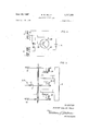
ELECTRONIC TIMEPIECE Filed Nov. 30, 1964 Y 5 Sheets-Sheet FIG. 4
FIG. 5 l 1 (m .I 9 I. I I
lNl ENTOR ROBERT WALTER RE/CH m g W ATTORNEVS R. W. REICH June 20, 1967 ELECTRONIC TIMEPIECE 5 SheetsSheet Filed Nov. 30, 1964 FIG. '7
//v VEN 70 "ROBERT WAL r51? R51 A TTOR/VEW United States Patent R 11 Claims. Cl. 318-128) This invention relates to electronic clocks and more particularly it relates to electronic driving means for an oscillating member which may also be used to drive the escapement mechanisms of a watch or clock.
Various electronic driving mechanisms for clocks are known. In applicants German Patent 1,150,327, for example, there is disclosed a circuit for electronic clocks in which a combination of coils is used for excitation and exertion of a driving force on an oscillating member of the driving mechanism. Use has already been made of the principle of excitation of coils by entering magnets at one side or by departing magnets on the other side for exerting a controlling impulse at the base of a transistor used in the circuit, causing the transistor to open and deliver a driving impulse to the running mechanism.
Experiments with the known driving mechanisms have revealed that magnets of relatively large size are always necessary to produce an opening impulse for the transistor circuit and consequently, the mechanical oscillating member such as a balance wheel is burdened with a heavy mass. In some instances, the balance wheel of electronically driven clocks is greater than the comparable part in a mechanically driven system.
As a result of the above, electronic driving of such timepieces with heavy magnets has been uneconomical. Since the intensity of the excitation impulse generated by the relative movement of magnets and coils depends upon the sizes thereof, many difiiculties have been encountered during efforts to produce such electronically operated timepieces.
Such circuits are especially critical in operation as to changes in voltage. Efforts have been made to alleviate the problem by artificially damping the oscillating memher during high voltage operation through the use of eddy currents, supplementaary coils, or other devices.
The above circuits are also temperature sensitive and accurate time keeping is not possible over wide temperature fluctuations. Some of the transistors used in the circuits have amplification factors which vary greatly with temperature fluctuations. If the circuit is designed in such a manner that low battery voltages of about 1 volt are sutficient to open the transistor completely, it is found that the required magnets and their associated coils must of necessity be very large. Consequently the timepieces will be much heavier and will require more power for their operation than would be necessary if the excitation developed would need to open the transistor only when the full operating voltage is applied.
The voltage for controlling a transistor can be varied only within the limits determined by the dimensions of the magnets and coils. The transistor can be modulated either at a low operating voltage, or at a higher voltage. To achieve at least partial compensation for voltage and temperature criticality, the elfort has generally been to make the excitation so powerful that the transistor will 'be modulated even by a low operating voltage. This necessitates a breaking of the oscillating movement, which in turn increases the power that has to be taken from the battery. As long as the battery voltage remains high, a portion of the power that is delivered to the driving coil will be dissipated and the normal energy balance will not be established until the battery voltage has dropped to a certain level.
Such a damping of the operating mechanism has also the disadvantage of becoming effective only after an oscillating movement of As soon as the oscillating movement becomes less than 180, such a damping means will cease to operate. The battery life has therefore been shortened sufliciently so that the available voltage will always be sufficient to cause the oscillating movement to exceed 180. Although a small battery would be able to operate an electronic timepiece for several years, the time for renewing it is generally established at about one year. Only in this manner can the mechanism be regulated during that period of time. As a result not more than 6 of the total life of the battery has been used.
This invention relates to an electronic mechanism for driving an oscillating member such as a balance wheel of a timepiece by means of a transistor circuit. Magnets are positioned on the oscillating member and stationary coils are positioned in the mechanism in such a manner that the magnets carried by the oscillating member will move in close proximity to the coils to generate an impulse in the exciter coils which will deliver a driving impulse over the transistor circuit to the collector or emitter circuit.
The magnets are secured on a thin non-magnetic plate which is fixed to rotate with the balance wheel and the magnets are positioned axially on the plate in spaced relationship to each other with opposite poles being secured to the plate.
A coil combination consisting of an exriter coil and a driver coil is placed above the magnets and a similar coil combination is placed below the magnets, and suitable iron discs or plates are fixed to rotate with the oscillating member and enclose the magnets and coils therebetween.
The spacing and sizes of the coils and magnets relative to one another is such that a triply strengthened impulse will be produced for both the excitation and the driving impulses by the simultaneous: (l) repulsion of a first magnet from the first coil combination; (2) repulsion of the second magnet from the second coil combination; and (3) attraction of the first magnet to said second coil combination or attraction of the second magnet to said first coil combination. With such a driving construction, the oscillating member or balance wheel can be made very small as well as the magnets, which will greatly reduce the weight of the balance wheel along with the height and depth thereof.
An object of this invention is to produce an electronically operated driving mechanism for a timepiece which is extremely compact, efiicient over wide temperature ranges and economical to produce.
A further object of this invention is to produce an electronically operated timepiece which will operate accurately over a wide fluctuation in voltage from a power source such as a battery and with a more complete utilization thereof.
A further object of this invention is to produce an electronically operated timepiece which is compact and also has a high energy balance to actuate a spring winding mechanism.
These and other objects and advantages of this invention will become more apparent from the following detailed description and accompanying drawings wherein:
FIGURE 1 is a side view of the electronic driving mechanism of this invention;
FIGURE 2 is a plan view of FIGURE 1;
FIGURE 3 is a diagram showing the relationship of the excitation impulse to the driving impulse during the time in which the magnets move into the coils;
FIGURE 4 is a diagram of a circuit used in this invention;
FIGURE is a side view of a second embodiment of this invention with magnets on the upper and lower plates in addition to those on the central plate;
FIGURE 6 is a diagrammatic view showing the driving means of this invention operatively connected to a spring winding mechanism; and
FIGURE 7 shows a perspective view of the coil support structure.
Referring to the drawings in more detail, FIGURES 1 and 2 show a first embodiment of the invention. The oscillating member shown is of the balance wheel variety comprising an axis 1 which is pivotally mounted in a bearing means In secured in a frame and to which axis is attached a plate 2 made of non-magnetic material and having the shape shown in FIGURE 2. There are two magnets 5 and 6 positioned in spaced relationship to each other and are secured to the plate 2 with their individual axes parallel to axis 1. Magnet 5 has its south pole facing upwardly as viewed in FIGURE 1 and magnet 6 has the north pole facing upwardly. There are suitable corresponding counterweights 13 and 14 positioned and secured to plate 2 as shown.
A coil combination 7 consisting of an exciter coil and a driver coil is positioned in a plane parallel to and above the plate 2 with the magnets thereon. A similar coil combination 8 consisting of an exciter coil and a driver coil is positioned in a plane parallel to and below the plate 2. Both coil combinations 7 and 8 are supported in coil support members 10 and 11, respectively, which are suitably secured to a support block means 9.
The dimensions of the wing segment 12 of plate 2 are determined by the required diameters of the magnets and their distance from each other. With a magnet diameter of about 5 mm. the total width of the segment need be only 20 mm. The non-magnetic counterbalancing weights 13 and 14 are secured to a similarly shaped segment 15 of plate 2.
The plates 2, 3, and 4 may be provided with notches or recesses to make them lighter. With a magnet diameter of 3 mm. the width of the wing segment 12 need be only 9 mm. wide, and with a magnet diameter of 1.5 mm. the wing segment correspondingly need be only 5 mm. wide. The weight of the balance wheel mm. in diameter according to this invention would be about 2 g. while in prior art constructions, the weight is generally at least 810 grams.
The diagram in FIGURE 3 shows the relation of the excitation impulse to the driver impulse during the time while the magnets move into the coils. During normal operation with the coils acting upon the magnets in a simple manner, a sinusoidal impulse of a certain voltage will be produced whose height must always be less than the maximum excitation voltage and current for complete opening of the transistor. These values for the modulation of the transistor are represented by the dotted line (a). In the driving system of this invention the excitation (e) is three times higher than the driving voltage (d), as rep resented by the curves on FIGURE 3.
In this system, even if there is a loweringof the battery voltage, the transistor will always be completely opened. In the driver coil, only such currents can flow as are permitted by the ohmic resistance of the coil in relation to the voltage of the battery. In the normal circuit the collector voltage is directly dependent on the battery voltage so that the current will diminish in linear relation to the battery voltage. In the circuit of this invention, however, the collector voltage remains the same during either high or low driver voltage because the transistor is always completely open. This will produce a more uniform amplitude throughout a wide voltage range.
A uniform amplitude throughout a fluctuating temperature range is also had by this invention. In the prior art circuits a temperature increase would produce increased current through the driver coil; however, in the circuit of this invention the transistor will always be completely open so that a current increase due to increased temperature is not possible.
This invention also has another advantage for driving a timepiece in that the prior art driving systems usually require amplitude swings of at least to to put the timepiece into operation. With this invention a swing of only a few degrees is suflicient to start the mechanism running normally. Even an electric connection of the transistor base through a resistor of the negative terminal of the battery will suflice completely so that by merely pressing a button, the mechanical oscillator can be started running and will be in normal operation after a few swings. Under all operating conditions, even with a lowering of the battery voltage, the amplitude of oscillation will be far beyond 180. No braking or damping of the balance wheel is required.
The two coil combinations of this invention are connected together as shown in FIGURE 4 and this arrangement has the advantage of permitting a small capacitor 2% to be connected between the two driver coils 7d and 8d with the other terminal of the capacitor being connected to the transistor base 22 which is especially helpful in starting. When the balance wheel movement is begun, the collector voltage will become negative and this negative voltage will be fed back through the capacitor to the transistor base.
This has the extraordinary advantage of providing a direct feedback of the driver impulse back to the base of the transistor. Since the connection between the two driver coils 7d and 8d is approximately half the driver voltage 24, the negative impulse which is fed to the base will be very strong. It is thereby possible to operate such a system by a battery which gives only 5 ma. on short circuit. This enables practically the entire range of short circuit current of about 8 to 10 amperes of the battery when new to be used until the battery is just about completely used up. This is in contrast to prior art mechanisms which utilize only about one-third of the useful life of the battery.
FIGURE 4 also shows the exciter coi-l 7c of coil combination 7 and the exciter coil 8e of coil combination 8 connected in series between the emitter 26 and base 22. The driver coils 7d and 8d are connected in series between the battery 24 and the collector 28.
FIGURE 5 shows a second modification of this invention wherein like numbers are used to identify similar parts. For small watches it may be advantageous to use very small flat magnets in both the middle segment and the upper and lower segments instead of the magnets 5 and 6 with the upper and lower closure plates 3 and 4'. In this manner it will be possible to use magnets of 1 mm. or less in diameter, and if very flat magnets are used, the height of the entire balance wheel structure can be reduced. The only requirement is that the dimensions of the magnets and the coils should be kept in proportion in such a manner that the exciter impulse and the driving impulse will be strengthened threefold.
The arrangement in FIGURE 5 may include magnets 30 and 32 which are positioned on the plate 2 similar to the arrangement shown in FIGURE 2. Magnet 34 is positioned or secured on plate 36 and is axially aligned with magnet 30 and magnet 38 is positioned and secured to plate 40 and is axially aligned with magnet 32. The plates 36 and 38 may be non-ferrous and may have the shape similar to that shown in FIGURE 2.
By the driving mechanism of this invention, a very high energy balance is obtained which may be used for winding up a spring housing, as shown diagrammatically in FIGURE 6. The driving mechanism generally designated 42 which may also include known ratchet systems for driving the shaft 44 extending therefrom and which shaft is rotatably mounted in a bearing 46. One plate 48 of a friction clutch is fixed to rotate with the shaft 44. A second plate 50 of the friction clutch is axially slidable on shaft 52 and fixed to rotate therewith. The shaft 52 is operatively connected to a spring means in housing 54 to tension the spring means therein. The spring means therein is operatively connected to a known time indicating mechanism 56.
The clutch coupling is used to maintain the spring means in the housing in the wound or tensioned state. A suitable lever support 58 is rotatably mounted on shaft 52 and is fixed to the frame of the mechanism. Lever 60 is pivotally mounted on coupling 58 and has a cam member 62 thereon. A spring member 64 secured to one end of lever and is fixed to the frame to urge cam member 62 into engagement with slidable clutch plate 50 and push it into engagement with the other friction plate 48 to thereby effect frictional driving engagement of the plates wtih each other so that driving mechanism 42 will wind the spring means in housing 54.
When the spring in the housing 54 is fully wound, a rotatable member 66 rotates to pull the other end of lever 66 via wire means 67 and thereby disengage clutch plate 50 from plate 48 and prevent overwinding of spring in the housing 54. A standard slip clutch arrangement (not shown) may also be used to effect the clutch coupling.
FIGURE 7 shows a perspective view of the coil support structure 9 and how the coil combinations 7 and 8 are positioned in two planes and how they are vertically offset from each other. A convenient way of connecting the coils in circuit is also shown. The coil support 9 has four pins 68 passing therethrough centrally of the coils and pass through coil support 10 and are exposed in a well 70 thereon. The ends of the coil combination 7 (shown as a single strand) can be then conveniently soldered to the appropriate pin 68 and connected in circuit as shown in FIGURE 4. The mounting and connecting of coil combination 8 on support 11 is similar although not shown in the drawings. The driver coil of each combination may be concentrically positioned inside the exciter coil.
It will be understood that this invention is susceptible to modification in order to adapt it to different usages and conditions and accordingly, it is desired to comprehend such modifications within this invention as may fall within the scope of the appended claims.
What is claimed is:
1. In an electronic timepiece, a balance wheel having shaft means pivotally supported for oscillation of the balance wheel on a given axis and having first and second permanent magnet means thereon with the magnetic axes of said magnet means being radially spaced from and parallel to said axis of said wheel and circumferentially spaced from each other and poled in respectively opposite directions, first and second stationary coil combination means in spaced parallel relationship to each other with the axes of said coil combination means being parallel to and radially spaced from said axis of said heel and circumferentially spaced from each other, said first and second coil combination means being adapted to be influenced by the movement of said magnet means relative thereto, each said coil combination means comprising an exciter coil and a driver coil concentric therewith, a transistor having a base, an emitter, and a collector, a source of voltage, first circuit means connecting said driver coils and said source of voltage in series between said emitter and said collector, second circuit means connecting said exciter coils in series between said emitter and said base, the spacing of the axes of said coil combination means from each other and from said axis being such that one of said first and second coil combination means is under the influence of both of said magnetic axes at the same time while the other thereof at the same time is under the influence of only one of said magnetic axes, whereby a triply strengthened electrical impulse will be generated in said exciter coils which will cause said transistor to deliver a driving impulse to said driving coils to provide a triply strengthened driving impulse to said balance wheel by the simultaneous. (a) repulsion of said first magnet means from said first coil combination means, (b) repulsion of said second magnet means from said second coil combination means, and (c) attraction of one of said first and second magnet means to one of said second and first coil combination means respectively.
2. The timepiece as claimed in claim 1 in which said balance wheel comprises middle, upper, and lower plate means which are in spaced parallel relationship to one another and are secured to said shaft means of said balance wheel with said middle plate means being made of non-magnetic material and said upper and lower plate means being made of magnetic material and with all said plate means being similarly dimensioned and axially aligned on said shaft means of said wheel, said first and second magnet means being secured on said middle plate means with opposite poles secured thereto, said first and second coil combination means being axially displaced from each other on opposite sides of the plane of said middle plate, said middle plate means with the magnet means thereon being adapted to oscillate in the axial space between said first and second coil combination means with said upper and lower plate means forming closure plates about said coil combination means.
3. The timepiece as claimed in claim 2 further comprising a capacitor having one end connected to said base of said transistor, said series connected driver coils having a junction therebetween to which the other end of said capacitor is connected.
4. The timepiece as claimed in claim 1 further comprising a capacitor having one end connected to said base of said transistor, said series connected driver coils having a junction therebetween to which the other end of said capacitor is connected.
5. The timepiece as claimed in claim 1 further comprising spring means, coupling means operatively connected to said balance wheel and said spring means for tensioning said spring means by said balance wheel, said coupling means comprising; clutch means having a first plate member operatively connected with said balance wheel and a second plate member operatively connected with said spring means, and means operatively connected with said spring means to bring said first and second plate members into operative engagement upon the running down of said spring means and to disengage said plate members upon the full tensioning of said spring means.
6. The timepiece as claimed in claim 1 further comprising support means for said first and second coil combination means, said support means comprising; support block means, first and second coil holder means secured to said block means and being parallel to each other and offset from each other for supporting said first and second coil combination means respectively, said circuit means comprising metal pins driven through said support block means and extending into said coil holder means in order to enable said ends of said driver and exciter coils to be connected to pertaining pins to connect them in circuit.
7. The timepiece as claimed in claim 1 in which said balance wheel comprises non-magnetic middle, upper and lower plate means which are in spaced parallel relationship to one another and are secured to said shaft means of said balance wheel, all said plate means being similarly dimensioned and axially aligned with respect to the axis of said wheel, said first magnet means comprising a first magnet secured to said middle plate means and a second magnet secured to said upper plate means and axially aligned with said first magnet, said second magnet means comprising a first magnet secured to said middle plate means and a second magnet secured to said lower plate means and axially aligned with the first magnet thereof, said first coil combination means being positioned between the planes formed by said upper and middle plate means, said second coil combination means being positioned between the planes formed by said middle and lower plate means.
8. The timepiece as claimed in claim 7 further comprising a capacitor having one end connected to said base of said transistor, said series connected driver coils having a junction therebctween to which the other end of said capacitor is connected.
9. The timepiece as claimed in claim 1 in which the axes of said first and second magnet means coincide respectively with the axes of said first and second coil combination means when said balance wheel is in its zero position.
10. In an electronic timepiece having a balance wheel oscillating member with magnet means thereon forming first and second axially directed circumferentially spaced magnetic axes poled in respectively opposite direction, first and second stationarily mounted circumferentially spaced substantially identical coil means each comprising concentrically arranged exciter and driver coils and having axes parallel to said magnetic axes and in the path of said magnetic axes so as to be influenced by the movement of said magnet axes relative thereto and transistorized circuit means connected to said coil means and adapted to receive impulses from said exciter coils and send driving impulses to said driver coils, said magnetic axes being circumferentially spaced a distance equal to the mean diameter of one of said exciter coils, said coil means being spaced circumferentially the same distance as said mag netic axes so that the sides of the respective exciter coils nearest each other are in overlapping relation whereby as one of said magnetic axes traverse the overlapping sides of said exciter coils the other magnetic axis will traverse the other side of one of said exciter coils thereby, said exciter coils being in series in said circuit means and said driver coils also being in circuit in said circuit means;
References Cited UNITED STATES PATENTS 2,986,683 5/1961 Lavet et al 31036 X 3,149,274 9/1964 HetZel 318-132 X FOREIGN PATENTS 353,691 5/ 1961 Switzerland.
MILTON O. HIRSHFIELD, Primary Examiner.
D. F. DUGGAN, Assistant Examiner.
Claims (1)
1. IN AN ELECTRONIC TIMEPIECE, A BALANCE WHEEL HAVING SHAFT MEANS PIVOTALLY SUPPORTED FOR OSCILLATION OF THE BALANCE WHEEL ON A GIVEN AXIS AND HAVING FIRST AND SECOND PERMANENT MAGNET MEANS THEREON WITH THE MAGNETIC AXES OF SAID MAGNET MEANS BEING RADIALLY SPACED FROM AND PARALLEL TO SAID AXIS OF SAID WHEEL AND CIRCUMFERENTIALLY SPACED FROM EACH OTHER AND POLED IN RESPECTIVELY OPPOSITE DIRECTIONS, FIRST AND SECOND STATIONARY COIL COMBINATION MEANS IN SPACED PARALLEL RELATIONSHIP TO EACH OTHER WITH THE AXES OF SAID COIL COMBINATION MEANS BEING PARALLEL TO AND RADIALLY SPACED FROM SAID AXIS OF SAID WHEEL AND CIRCUMFERENTIALLY SPACED FROM EACH OTHER, SAID FIRST AND SECOND COIL COMBINATION MEANS BEING ADAPTED TO BE INFLUENCED BY THE MOVEMENT OF SAID MAGNET MEANS RELATIVE THERETO, EACH SAID COIL COMBINATION MEANS COMPRISING AN EXCITER COIL AND A DRIVER COIL CONCENTRIC THEREWITH, A TRANSISTOR HAVING BASE, AN EMITTER, AND A COLLECTOR, A SOURCE OF VOLTAGE, FIRST CIRCUIT MEANS CONNECTING SAID DRIVER COILS AND SAID SOURCE OF VOLTAGE IN SERIES BETWEEN SAID EMITTER AND SAID COLLECTOR, SECOND CIRCUIT MEANS CONNECTING SAID EXCITER COILS IN SERIES BETWEEN SAID EMITTER AND SAID BASE, THE SPACING OF THE AXES OF SAID COIL COMBINATION MEANS FROM EACH OTHER AND FROM SAID AXIS BEING SUCH THAT ONE OF SAID FIRST AND SECOND COIL COMBINATION MEANS IS UNDER THE INFLUENCE OF ONLY ONE OF SAID MAGNETIC AXES AT THE SAME TIME WHILE THE OTHER THEREOF AT THE SAME TIME IS UNDER THE INFLUENCE OF ONLY ONE OF SAID MAGNETIC AXES, WHEREBY A TRIPLY STRENGTHENED ELECTRICAL IMPLUSE WILL BE GENERATED IN SAID EXCITER COILS WHICH WILL CAUSE SAID TRANSISTOR TO DELIVER A DRIVING IMPULSE TO SAID DRIVING COILS TO PROVIDE A TRIPLY STRENGTHENED DRIVING IMPULSE TO SAID BALANCE WHEEL BY THE SIMULTANEOUS: (A) REPULSION OF SAID FIRST MAGNET MEANS FROM SAID FIRST COIL COMBINATION MEANS, (B) REPULSION OF SAID SECOND MAGNET MEANS FROM SAID SECOND COIL COMBINATION MEANS, AND (C) ATTRACTION OF ONE OF SAID FIRST AND SECOND MAGNET MEANS TO ONE OF SAID SECOND AND FIRST COIL COMBINATION MEANS RESPECTIVELY.
Applications Claiming Priority (1)
| Application Number | Priority Date | Filing Date | Title |
|---|---|---|---|
| DER36699A DE1300867B (en) | 1963-12-02 | 1963-12-02 | Electronic clock drive |
Publications (1)
| Publication Number | Publication Date |
|---|---|
| US3327190A true US3327190A (en) | 1967-06-20 |
Family
ID=7404985
Family Applications (1)
| Application Number | Title | Priority Date | Filing Date |
|---|---|---|---|
| US414702A Expired - Lifetime US3327190A (en) | 1963-12-02 | 1964-11-30 | Electronic timepiece |
Country Status (4)
| Country | Link |
|---|---|
| US (1) | US3327190A (en) |
| CH (2) | CH452447A (en) |
| DE (1) | DE1300867B (en) |
| GB (1) | GB1086306A (en) |
Cited By (4)
| Publication number | Priority date | Publication date | Assignee | Title |
|---|---|---|---|---|
| US3430119A (en) * | 1965-07-22 | 1969-02-25 | Smiths Industries Ltd | Oscillating motor for horological instruments |
| US3589122A (en) * | 1968-03-20 | 1971-06-29 | Kienzle Uhrenfabriken Gmbh | Electrodynamic oscillator |
| US3713047A (en) * | 1969-12-09 | 1973-01-23 | Kroewerath S & Co Fa | Oscillator with electrodynamic drive and electromagnetic detection, especially for use in an electronic clock |
| US3845339A (en) * | 1971-09-01 | 1974-10-29 | Papst Motoren Kg | Permanent magnet rotor electric motor |
Citations (3)
| Publication number | Priority date | Publication date | Assignee | Title |
|---|---|---|---|---|
| CH353691A (en) * | 1959-03-26 | 1961-04-15 | Movado Montres | Electromagnetic maintenance device for a sprung balance assembly |
| US2986683A (en) * | 1956-07-26 | 1961-05-30 | Hatot Leon Ets | Driving balance-wheels more particularly applicable to timing instruments |
| US3149274A (en) * | 1962-01-17 | 1964-09-15 | Bulova Watch Co Inc | Electromagnetic vibrating drive |
Family Cites Families (2)
| Publication number | Priority date | Publication date | Assignee | Title |
|---|---|---|---|---|
| DE1157158B (en) * | 1956-07-26 | 1963-11-07 | Hatot Leon Ets | Gear folder with permanent magnets for timing devices, which interacts with an electronic circuit |
| FR1224395A (en) * | 1959-03-24 | 1960-06-23 | Hatot Leon Ets | Improvements to magnetoelectric devices applicable in particular to electronic watches |
-
1963
- 1963-12-02 DE DER36699A patent/DE1300867B/en active Pending
-
1964
- 1964-08-14 CH CH1068764A patent/CH452447A/en unknown
- 1964-08-14 CH CH1068764D patent/CH1068764A4/xx unknown
- 1964-11-18 GB GB46868/64A patent/GB1086306A/en not_active Expired
- 1964-11-30 US US414702A patent/US3327190A/en not_active Expired - Lifetime
Patent Citations (3)
| Publication number | Priority date | Publication date | Assignee | Title |
|---|---|---|---|---|
| US2986683A (en) * | 1956-07-26 | 1961-05-30 | Hatot Leon Ets | Driving balance-wheels more particularly applicable to timing instruments |
| CH353691A (en) * | 1959-03-26 | 1961-04-15 | Movado Montres | Electromagnetic maintenance device for a sprung balance assembly |
| US3149274A (en) * | 1962-01-17 | 1964-09-15 | Bulova Watch Co Inc | Electromagnetic vibrating drive |
Cited By (4)
| Publication number | Priority date | Publication date | Assignee | Title |
|---|---|---|---|---|
| US3430119A (en) * | 1965-07-22 | 1969-02-25 | Smiths Industries Ltd | Oscillating motor for horological instruments |
| US3589122A (en) * | 1968-03-20 | 1971-06-29 | Kienzle Uhrenfabriken Gmbh | Electrodynamic oscillator |
| US3713047A (en) * | 1969-12-09 | 1973-01-23 | Kroewerath S & Co Fa | Oscillator with electrodynamic drive and electromagnetic detection, especially for use in an electronic clock |
| US3845339A (en) * | 1971-09-01 | 1974-10-29 | Papst Motoren Kg | Permanent magnet rotor electric motor |
Also Published As
| Publication number | Publication date |
|---|---|
| DE1300867B (en) | 1969-08-07 |
| GB1086306A (en) | 1967-10-11 |
| CH1068764A4 (en) | 1967-11-15 |
| CH452447A (en) | 1967-11-15 |
Similar Documents
| Publication | Publication Date | Title |
|---|---|---|
| US3168690A (en) | Clock power-device | |
| JP4722445B2 (en) | Watch with mechanical movement connected to an electronic regulator | |
| JP4630621B2 (en) | Watch with mechanical movement connected to an electronic regulator | |
| US2606222A (en) | Electric motor | |
| US3156857A (en) | Electrodynamic rate regulator arrangement for clocks | |
| US3375423A (en) | Synchronous motor, especially for electric clocks | |
| US2598912A (en) | Movement for electric timepieces | |
| US3207965A (en) | Adjustable mechanical oscillator for time-measuring apparatus | |
| US3327190A (en) | Electronic timepiece | |
| GB746465A (en) | Improved electromagnetic impulse device for driving clocks | |
| US3407344A (en) | Electronic timekeeper | |
| US3002138A (en) | Electrically powered oscillatory balance | |
| US2988868A (en) | Electronic time-measuring arrangement | |
| US2961587A (en) | Timepiece | |
| US3123755A (en) | Electrical system for maintenance of | |
| US2708737A (en) | Instrument damping system | |
| US3124730A (en) | Thoma | |
| US3596461A (en) | Electromagnetic driving system for timepieces | |
| US3312883A (en) | Driving mechanism of a torsional oscillator | |
| US2835105A (en) | Electrostatic balance clock | |
| US1826719A (en) | Self-oscillating electric clock | |
| US2632292A (en) | Impulse electric clock | |
| US3999369A (en) | Electromechanical watch movement | |
| US3010075A (en) | Electric watch | |
| US3787783A (en) | Time-keeping device with transistor control using oscillating magnet |