US3292746A - Vibration dampener for disk brakes - Google Patents
Vibration dampener for disk brakes Download PDFInfo
- Publication number
- US3292746A US3292746A US506518A US50651865A US3292746A US 3292746 A US3292746 A US 3292746A US 506518 A US506518 A US 506518A US 50651865 A US50651865 A US 50651865A US 3292746 A US3292746 A US 3292746A
- Authority
- US
- United States
- Prior art keywords
- walls
- brake
- radially extending
- disk
- brake disk
- Prior art date
- Legal status (The legal status is an assumption and is not a legal conclusion. Google has not performed a legal analysis and makes no representation as to the accuracy of the status listed.)
- Expired - Lifetime
Links
- 238000010276 construction Methods 0.000 description 7
- 230000000712 assembly Effects 0.000 description 2
- 238000000429 assembly Methods 0.000 description 2
- 238000012423 maintenance Methods 0.000 description 2
- 238000004519 manufacturing process Methods 0.000 description 2
- 238000012986 modification Methods 0.000 description 2
- 230000004048 modification Effects 0.000 description 2
- 238000001816 cooling Methods 0.000 description 1
- 238000009434 installation Methods 0.000 description 1
Images


Classifications
-
- F—MECHANICAL ENGINEERING; LIGHTING; HEATING; WEAPONS; BLASTING
- F16—ENGINEERING ELEMENTS AND UNITS; GENERAL MEASURES FOR PRODUCING AND MAINTAINING EFFECTIVE FUNCTIONING OF MACHINES OR INSTALLATIONS; THERMAL INSULATION IN GENERAL
- F16D—COUPLINGS FOR TRANSMITTING ROTATION; CLUTCHES; BRAKES
- F16D65/00—Parts or details
- F16D65/02—Braking members; Mounting thereof
- F16D65/12—Discs; Drums for disc brakes
-
- F—MECHANICAL ENGINEERING; LIGHTING; HEATING; WEAPONS; BLASTING
- F16—ENGINEERING ELEMENTS AND UNITS; GENERAL MEASURES FOR PRODUCING AND MAINTAINING EFFECTIVE FUNCTIONING OF MACHINES OR INSTALLATIONS; THERMAL INSULATION IN GENERAL
- F16D—COUPLINGS FOR TRANSMITTING ROTATION; CLUTCHES; BRAKES
- F16D65/00—Parts or details
- F16D65/02—Braking members; Mounting thereof
- F16D2065/13—Parts or details of discs or drums
- F16D2065/1304—Structure
- F16D2065/1308—Structure one-part
-
- F—MECHANICAL ENGINEERING; LIGHTING; HEATING; WEAPONS; BLASTING
- F16—ENGINEERING ELEMENTS AND UNITS; GENERAL MEASURES FOR PRODUCING AND MAINTAINING EFFECTIVE FUNCTIONING OF MACHINES OR INSTALLATIONS; THERMAL INSULATION IN GENERAL
- F16D—COUPLINGS FOR TRANSMITTING ROTATION; CLUTCHES; BRAKES
- F16D65/00—Parts or details
- F16D65/02—Braking members; Mounting thereof
- F16D2065/13—Parts or details of discs or drums
- F16D2065/134—Connection
- F16D2065/1384—Connection to wheel hub
-
- F—MECHANICAL ENGINEERING; LIGHTING; HEATING; WEAPONS; BLASTING
- F16—ENGINEERING ELEMENTS AND UNITS; GENERAL MEASURES FOR PRODUCING AND MAINTAINING EFFECTIVE FUNCTIONING OF MACHINES OR INSTALLATIONS; THERMAL INSULATION IN GENERAL
- F16D—COUPLINGS FOR TRANSMITTING ROTATION; CLUTCHES; BRAKES
- F16D65/00—Parts or details
- F16D65/02—Braking members; Mounting thereof
- F16D2065/13—Parts or details of discs or drums
- F16D2065/134—Connection
- F16D2065/1392—Connection elements
Definitions
- An object of the invention is to provide means for dampening the vibrations of a disk brake.
- Another object of the invention is to provide means for minimizing or preventing vibrations in a disk brake consisting of the provision of a wire dampening member interposed between the spaced walls of the brake disk and engaging the webs extending between said spaced walls.
- Another object of this invention is to provide a device of this type which is so reduced in the number and char acter of its component parts as to approach the ultimate in structural simplicity to thereby create an economy in its manufacture, installation and maintenance costs.
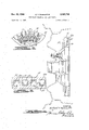
- FIGURE 1 is a vertical sectional view through a brake disk embodying this invention, taken substantially on the plane indicated by line 1-1 in FIGURE 2, the wheel and rim being shown in dotted lines;
- FIGURE 2 in an elevational view, partly in section, of the brake disk shown in FIGURE 1;
- FIGURE 3 is an enlarged fragmentary sectional view taken substantially on the plane indicated by line 33 in FIGURE 2;
- FIGURE 4 is a view similar to FIGURE 1 showing a modified dampening member
- FIGURE 5 is a fragmentary view similar to FIGURE 2, showing this modification.
- FIGURE 6 is an enlarged fragmentary sectional view taken substantially on the plane indicated by line 66 in FIGURE 5.
- the brake of this invention is shown as being associated with a vehicle wheel having a rim 10 and a wheel body 11 secured to the axle flange 12 by means of studs or bolt and nut assemblies 13.
- the brake disk 15 is formed of a pair of spaced walls 15a and 15b with which the brake shoes (not shown) engage.
- the brake disk is provided with a plurality of radially extending apertures 16 formed by radially extending webs or walls 17 extending between and connected to the spaced walls 15a and 15b.
- the webs 17 function as fan blades and serve to move cooling air in a radially outward direction between the walls 15a and 15b when the brake is rotated. It will be noted from FIGURE 1 that the apertures 16 are open at their radially inner and outer ends.
- an object of this invention is to provide means for dampening the vibrations in the disk brake which are set up by the frictional engagement of the brake shoes with the braking surfaces of the disk brake.
- a spring wire member 20 bent into circular shape and provided with a plurality of lobes or loops 21 which are pressed into the openings 16 between the radially extending webs orwalls 17.
- Each loop 21 is provided with opposed outwardly bowed portions -22 which frictionally engage the radially extending walls 17 and assist in holding the spring member 20- in place.
- the loops 21 at their outwardly bowed portions 22 are slightly larger than the space between the webs or walls 17, so that these loops will frictionally engage the adjacent webs 17 to provide a press fit between these parts.
- the lobes or loops 21 of the member 20 perform the desired function of dampening the vibrations set up in the brake disks.
- the spring wire member 20 may be made in a straight length and then bent into circular shape with the ends thereof permanently connected. It will be noted that the passageways or apertures 16 extend radially outwardly between adjacent webs or walls 17 so that the wire member may .be conveniently inserted into the spaces 16 from the radially inner ends thereof.
- FIGURES 4, 5 and 6 there is shown a spring wire member 30 bent into circular shape and provided with a plurality of lobes or loops 31 which are pressed into the openings 16 between the radially extending webs or walls 17 of the brake disk 15.
- Each loop 31 is provided with opposed bowed portions 32, as in the first described construction, which fn'ctionally engage the radially extending walls 17 and assist in holding the spring member 30 in place.
- the loops 31 at their outwardly bowed portions 32 are slightly larger than the space between the webs or walls 17 so that these loops will frictionally engage the adjacent webs 17 to provide a press fit between these parts.
- the loops 31 are alternately bent in opposite directions against the outside walls 16a of the openings 16, as best shown in FIGURES 4 and 6.
- each loop 31 frictionally engages the brake disk 15 at a plurality of points and the loops are alternately oppositely inclined so as to balance the construction.
- a brake comprising a brake disk having a pair of axially spaced walls connected by circumferentially spaced, radially extending walls, and a circular vibration dampening member having loop portions extending into the space between said radial walls in frictional engagement therewith.
- a brake comprising a brake disk formed of a pair of axially spaced walls connected by circumferentially spaced, radially extending walls forming a plurality of radially extending apertures, and a circular vibration dampening member formed of wire and having loop portions extending into said apertures in frictional engagement with said radially extending walls.
- a brake comprising a brake disk formed of a pair of axially spaced walls connected by circumferentially spaced, radially extending walls forming a plurality of radially extending"aperturesfand a circulan'vibr'a'tion" dampening member formed of spring wire and having lobe portions extending into said apertures from the radially inner'ends thereof in friction-a1 engagement with said radially extending walls.
- Abrake comprising a brake disk formed'of a pair of axially spaced walls connected by circumferentially spaced, radially extending walls forming a plurality of radially extending apertures, and a circular vibration dampening member formed of spring wire and having circumferentially spaced loop portions extending into said apertures, each loop portion having outwardly bowed sides for frictional engagement with said radially extending walls.
- a brake comprising a brake disk formed of a pair of axially spaced walls connected by circumferentially. spaced, radially extending" walls forming a plurality. of radially extending apertures and a circular vibration dampening member formed of spring wire and having circumferentially spaced loop portions extending into said 1 apertures, each loop portion having outwardly bowed sides-for frictional engagement with said radially extending walls, said loops being alternately oppositely inclined so as to engage the adjacent outer wall of the brake disk.
Landscapes
- Engineering & Computer Science (AREA)
- General Engineering & Computer Science (AREA)
- Mechanical Engineering (AREA)
- Braking Arrangements (AREA)
Description
Dec. 20, 1966 R. T. ROBINETTE 3,292,746
VIBRATION DAMPENER FOR DISK BRAKES Filed Nov. 5, 1965 5 Sheets-Sheet l INVENTOR.
Dec. 20, 1966 R. T. ROBINETTE VIBRATION DAMPENER FOR DISK BRAKES 3 Sheets-Sheet 2 Filed NOV. 5, 1965 INVENTOR Dec. 20, 1966 R. T. ROBINETTE VIBRATION DAMPENER FOR DISK BRAKES 5 Sheets-Sheet 5 Filed Nov. 5, 1965 INV N 0 J 712%424 7' 27422723 2 6: fi-
United States Patent 3,292,746 VIBRATION DAMPENER FOR DISK BRAKES Richard T. Robinette, St. Clair Shores, Mich., assignor to Kelsey-Hayes Company, Romulus, Micln, a corporation of Delaware Filed Nov. 5, 1965, Ser. No. 506,518 Claims. (Cl. 188-218) This invention relates to disk brakes and, more particularly, to vibration dampeners therefor.
In the automotive industry, considerable difiiculty has been experienced in dampening the audible vibrations set up in the brake disk through the frictional engagement of the .brake shoes with the brake disk. These audible vibrations occur at certain periods of vibration of the brake disk and produce a noise which is annoying and objectionable. The present invention is designed to overcome these objections.
An object of the invention is to provide means for dampening the vibrations of a disk brake.
Another object of the invention is to provide means for minimizing or preventing vibrations in a disk brake consisting of the provision of a wire dampening member interposed between the spaced walls of the brake disk and engaging the webs extending between said spaced walls.
Another object of this invention is to provide a device of this type which is so reduced in the number and char acter of its component parts as to approach the ultimate in structural simplicity to thereby create an economy in its manufacture, installation and maintenance costs.
The various objects and advantages, and the novel details of construction of one commercially practical embodiment of the invention, will become more apparent as this description proceeds, especially when considered in connection with the accompanying drawings, in which:
FIGURE 1 is a vertical sectional view through a brake disk embodying this invention, taken substantially on the plane indicated by line 1-1 in FIGURE 2, the wheel and rim being shown in dotted lines;
FIGURE 2 in an elevational view, partly in section, of the brake disk shown in FIGURE 1;
FIGURE 3 is an enlarged fragmentary sectional view taken substantially on the plane indicated by line 33 in FIGURE 2;
FIGURE 4 is a view similar to FIGURE 1 showing a modified dampening member;
FIGURE 5 is a fragmentary view similar to FIGURE 2, showing this modification; and
FIGURE 6 is an enlarged fragmentary sectional view taken substantially on the plane indicated by line 66 in FIGURE 5.
The brake of this invention is shown as being associated with a vehicle wheel having a rim 10 and a wheel body 11 secured to the axle flange 12 by means of studs or bolt and nut assemblies 13.
Also secured to the flange 12, as for instance by means of the same studs or bolt and nut assemblies 13, is a brake disk 15. In the form of the invention illustrated, the brake disk 15 is formed of a pair of spaced walls 15a and 15b with which the brake shoes (not shown) engage. The brake disk is provided with a plurality of radially extending apertures 16 formed by radially extending webs or walls 17 extending between and connected to the spaced walls 15a and 15b. The webs 17 function as fan blades and serve to move cooling air in a radially outward direction between the walls 15a and 15b when the brake is rotated. It will be noted from FIGURE 1 that the apertures 16 are open at their radially inner and outer ends.
As stated, an object of this invention is to provide means for dampening the vibrations in the disk brake which are set up by the frictional engagement of the brake shoes with the braking surfaces of the disk brake.
For this purpose, there is provided a spring wire member 20 bent into circular shape and provided with a plurality of lobes or loops 21 which are pressed into the openings 16 between the radially extending webs orwalls 17. Each loop 21 is provided with opposed outwardly bowed portions -22 which frictionally engage the radially extending walls 17 and assist in holding the spring member 20- in place. The loops 21 at their outwardly bowed portions 22 are slightly larger than the space between the webs or walls 17, so that these loops will frictionally engage the adjacent webs 17 to provide a press fit between these parts. Thus, the lobes or loops 21 of the member 20 perform the desired function of dampening the vibrations set up in the brake disks.
The spring wire member 20 may be made in a straight length and then bent into circular shape with the ends thereof permanently connected. It will be noted that the passageways or apertures 16 extend radially outwardly between adjacent webs or walls 17 so that the wire member may .be conveniently inserted into the spaces 16 from the radially inner ends thereof.
In the modification illustrated in FIGURES 4, 5 and 6, there is shown a spring wire member 30 bent into circular shape and provided with a plurality of lobes or loops 31 which are pressed into the openings 16 between the radially extending webs or walls 17 of the brake disk 15. Each loop 31 is provided with opposed bowed portions 32, as in the first described construction, which fn'ctionally engage the radially extending walls 17 and assist in holding the spring member 30 in place. As in the previously described construction, the loops 31 at their outwardly bowed portions 32 are slightly larger than the space between the webs or walls 17 so that these loops will frictionally engage the adjacent webs 17 to provide a press fit between these parts. However, in this form of construction, the loops 31 are alternately bent in opposite directions against the outside walls 16a of the openings 16, as best shown in FIGURES 4 and 6.
With the foregoing construction, the outwardly bowed portions 32 frictionally engage the radially extending walls 17 and the outer ends of the loops 31 alternately frictionally engage the outer walls 161: of the openings 16. Thus, in this form of construction, each loop 31 frictionally engages the brake disk 15 at a plurality of points and the loops are alternately oppositely inclined so as to balance the construction.
From the foregoing, it will be seen that there is provided a simple device for dampening the vibrations in the brake disk which is inexpensive to manufacture, easy to install and which requires little, if any, maintenance costs.
While two commercially practical embodiments of the invention have been described and illustrated herein somewhat in detail, it will be understood that various changes may be made as may come within the purview of the accompanying claims.
What is claimed is:
1. A brake comprising a brake disk having a pair of axially spaced walls connected by circumferentially spaced, radially extending walls, and a circular vibration dampening member having loop portions extending into the space between said radial walls in frictional engagement therewith.
2. A brake comprising a brake disk formed of a pair of axially spaced walls connected by circumferentially spaced, radially extending walls forming a plurality of radially extending apertures, and a circular vibration dampening member formed of wire and having loop portions extending into said apertures in frictional engagement with said radially extending walls.
3. A brake comprising a brake disk formed of a pair of axially spaced walls connected by circumferentially spaced, radially extending walls forming a plurality of radially extending"aperturesfand a circulan'vibr'a'tion" dampening member formed of spring wire and having lobe portions extending into said apertures from the radially inner'ends thereof in friction-a1 engagement with said radially extending walls.
4. Abrake comprising a brake disk formed'of a pair of axially spaced walls connected by circumferentially spaced, radially extending walls forming a plurality of radially extending apertures, and a circular vibration dampening member formed of spring wire and having circumferentially spaced loop portions extending into said apertures, each loop portion having outwardly bowed sides for frictional engagement with said radially extending walls.
5. A brake comprising a brake disk formed of a pair of axially spaced walls connected by circumferentially. spaced, radially extending" walls forming a plurality. of radially extending apertures and a circular vibration dampening member formed of spring wire and having circumferentially spaced loop portions extending into said 1 apertures, each loop portion having outwardly bowed sides-for frictional engagement with said radially extending walls, said loops being alternately oppositely inclined so as to engage the adjacent outer wall of the brake disk.
9/1956 Fleischman 188-1
Claims (1)
1. A BRAKE COMPRISING A BRAKE DISK HAVING A PAIR OF AXIALLY SPACED WALLS CONNECTED BY CIRCUMFERENTIALLY SPACED, RADIALLY EXTENDING WALLS, AND A CIRCULAR VIBRATION DAMPENING MEMBER HAVING LOOP PORTIONS EXTENDING INTO THE SPACE BETWEEN SAID RADIAL WALLS IN FRICTIONAL ENGAGEMENT THEREWITH.
Priority Applications (1)
| Application Number | Priority Date | Filing Date | Title |
|---|---|---|---|
| US506518A US3292746A (en) | 1965-11-05 | 1965-11-05 | Vibration dampener for disk brakes |
Applications Claiming Priority (1)
| Application Number | Priority Date | Filing Date | Title |
|---|---|---|---|
| US506518A US3292746A (en) | 1965-11-05 | 1965-11-05 | Vibration dampener for disk brakes |
Publications (1)
| Publication Number | Publication Date |
|---|---|
| US3292746A true US3292746A (en) | 1966-12-20 |
Family
ID=24014919
Family Applications (1)
| Application Number | Title | Priority Date | Filing Date |
|---|---|---|---|
| US506518A Expired - Lifetime US3292746A (en) | 1965-11-05 | 1965-11-05 | Vibration dampener for disk brakes |
Country Status (1)
| Country | Link |
|---|---|
| US (1) | US3292746A (en) |
Cited By (43)
| Publication number | Priority date | Publication date | Assignee | Title |
|---|---|---|---|---|
| US3366202A (en) * | 1966-12-19 | 1968-01-30 | Budd Co | Brake disk and balance weight combination |
| US3368654A (en) * | 1966-08-15 | 1968-02-13 | Bendix Corp | Ventilated disc balance weight |
| US3452845A (en) * | 1968-03-15 | 1969-07-01 | Micropoise Eng & Sales Co | Brake disc and balancing weight |
| US5004078A (en) * | 1988-11-09 | 1991-04-02 | Aisin Takaoka Co., Ltd. | Ventilated disk and process for making same |
| DE19533326A1 (en) * | 1995-09-08 | 1997-03-13 | Bayerische Motoren Werke Ag | Vibration absorber for internally vented brake discs |
| US5855257A (en) * | 1996-12-09 | 1999-01-05 | Chrysler Corporation | Damper for brake noise reduction |
| US6112865A (en) * | 1996-12-09 | 2000-09-05 | Chrysler Corporation | Damper for brake noise reduction (brake drums) |
| US20050011628A1 (en) * | 2003-07-18 | 2005-01-20 | John Frait | Method and apparatus for forming a part with dampener |
| US20060076200A1 (en) * | 2004-10-08 | 2006-04-13 | Dessouki Omar S | Coulomb friction damped disc brake rotors |
| US20070056815A1 (en) * | 2005-09-15 | 2007-03-15 | Hanna Michael D | Bi-metal disc brake rotor and method of manufacturing |
| US20070062664A1 (en) * | 2005-09-20 | 2007-03-22 | Schroth James G | Method of casting components with inserts for noise reduction |
| US20070062768A1 (en) * | 2005-09-19 | 2007-03-22 | Hanna Michael D | Bi-metal disc brake rotor and method of manufacturing |
| US20070235270A1 (en) * | 2006-04-11 | 2007-10-11 | Thyssenkrupp-Waupaca Division | Insert for manufacture of an enhanced sound dampening composite rotor casting and method thereof |
| US20070298275A1 (en) * | 2006-06-27 | 2007-12-27 | Gm Global Technology Operations, Inc. | Damped automotive components with cast in place inserts and method of making same |
| US20090020379A1 (en) * | 2006-05-25 | 2009-01-22 | Gm Global Technology Operations, Inc. | Low Mass Multi-Piece Sound Dampened Article |
| US20090020256A1 (en) * | 2007-07-20 | 2009-01-22 | Gm Global Technology Operations, Inc. | Method of casting damped part with insert |
| US20090020383A1 (en) * | 2006-06-27 | 2009-01-22 | Gm Global Technology Operations, Inc. | Damped part |
| US20090032569A1 (en) * | 2007-08-01 | 2009-02-05 | Gm Global Technology Operations, Inc. | Friction welding method and products made using the same |
| US20090032674A1 (en) * | 2007-08-01 | 2009-02-05 | Gm Global Technology Operations, Inc. | Damped product with insert and method of making the same |
| US20090078520A1 (en) * | 2007-09-24 | 2009-03-26 | Gm Global Technology Operations, Inc. | Insert with tabs and damped products and methods of making the same |
| US20090107787A1 (en) * | 2007-10-29 | 2009-04-30 | Gm Global Technology Operations, Inc. | Inserts with holes for damped products and methods of making and using the same |
| US7594568B2 (en) | 2005-11-30 | 2009-09-29 | Gm Global Technology Operations, Inc. | Rotor assembly and method |
| US20090260932A1 (en) * | 2008-04-18 | 2009-10-22 | Gm Global Technology Operations, Inc. | Chamber with filler material to dampen vibrating components |
| US20090260939A1 (en) * | 2008-04-18 | 2009-10-22 | Gm Global Technology Operations, Inc. | Insert with filler to dampen vibrating components |
| US20100276236A1 (en) * | 2009-05-01 | 2010-11-04 | Gm Global Technology Operations, Inc. | Damped product and method of making the same |
| US8020300B2 (en) | 2007-08-31 | 2011-09-20 | GM Global Technology Operations LLC | Cast-in-place torsion joint |
| US8091609B2 (en) | 2008-01-04 | 2012-01-10 | GM Global Technology Operations LLC | Method of forming casting with frictional damping insert |
| US8118079B2 (en) | 2007-08-17 | 2012-02-21 | GM Global Technology Operations LLC | Casting noise-damped, vented brake rotors with embedded inserts |
| US8163399B2 (en) | 2004-10-08 | 2012-04-24 | GM Global Technology Operations LLC | Damped products and methods of making and using the same |
| US8210232B2 (en) | 2007-09-20 | 2012-07-03 | GM Global Technology Operations LLC | Lightweight brake rotor and components with composite materials |
| US8245758B2 (en) | 2006-10-30 | 2012-08-21 | GM Global Technology Operations LLC | Coulomb damped disc brake rotor and method of manufacturing |
| US20140090935A1 (en) * | 2007-05-16 | 2014-04-03 | Polaris Industries Inc. | All terrain vehicle |
| DE102013005067A1 (en) * | 2013-03-22 | 2014-04-24 | Audi Ag | Ventilated brake disk for motor car, has friction ring arranged parallel to another friction ring and provided with ring surface, cooling channels arranged between friction rings, and annular segments arranged between friction rings |
| US8714232B2 (en) | 2010-09-20 | 2014-05-06 | GM Global Technology Operations LLC | Method of making a brake component |
| US8758902B2 (en) | 2007-07-20 | 2014-06-24 | GM Global Technology Operations LLC | Damped product with an insert having a layer including graphite thereon and methods of making and using the same |
| US9127734B2 (en) | 2009-04-08 | 2015-09-08 | GM Global Technology Operations LLC | Brake rotor with intermediate portion |
| US9163682B2 (en) | 2008-07-24 | 2015-10-20 | GM Global Technology Operations LLC | Friction damped brake drum |
| EP3051168A1 (en) * | 2015-01-29 | 2016-08-03 | FCA Italy S.p.A. | Ventilated brake disk for a motor vehicle |
| US9500242B2 (en) | 2008-12-05 | 2016-11-22 | GM Global Technology Operations LLC | Component with inlay for damping vibrations |
| US9527132B2 (en) | 2007-07-20 | 2016-12-27 | GM Global Technology Operations LLC | Damped part with insert |
| US9534651B2 (en) | 2007-07-20 | 2017-01-03 | GM Global Technology Operations LLC | Method of manufacturing a damped part |
| USD783474S1 (en) * | 2016-04-28 | 2017-04-11 | Ausco Products, Inc. | Brake |
| USD807260S1 (en) * | 2016-04-11 | 2018-01-09 | Christopher Mark Young | Brake conversion hub |
Citations (1)
| Publication number | Priority date | Publication date | Assignee | Title |
|---|---|---|---|---|
| US2764260A (en) * | 1952-01-26 | 1956-09-25 | Gen Motors Corp | Vibration dampening means for brakes, clutches, and the like |
-
1965
- 1965-11-05 US US506518A patent/US3292746A/en not_active Expired - Lifetime
Patent Citations (1)
| Publication number | Priority date | Publication date | Assignee | Title |
|---|---|---|---|---|
| US2764260A (en) * | 1952-01-26 | 1956-09-25 | Gen Motors Corp | Vibration dampening means for brakes, clutches, and the like |
Cited By (65)
| Publication number | Priority date | Publication date | Assignee | Title |
|---|---|---|---|---|
| US3368654A (en) * | 1966-08-15 | 1968-02-13 | Bendix Corp | Ventilated disc balance weight |
| US3366202A (en) * | 1966-12-19 | 1968-01-30 | Budd Co | Brake disk and balance weight combination |
| US3452845A (en) * | 1968-03-15 | 1969-07-01 | Micropoise Eng & Sales Co | Brake disc and balancing weight |
| US5004078A (en) * | 1988-11-09 | 1991-04-02 | Aisin Takaoka Co., Ltd. | Ventilated disk and process for making same |
| DE19533326A1 (en) * | 1995-09-08 | 1997-03-13 | Bayerische Motoren Werke Ag | Vibration absorber for internally vented brake discs |
| US5855257A (en) * | 1996-12-09 | 1999-01-05 | Chrysler Corporation | Damper for brake noise reduction |
| US6112865A (en) * | 1996-12-09 | 2000-09-05 | Chrysler Corporation | Damper for brake noise reduction (brake drums) |
| WO2005007323A1 (en) * | 2003-07-18 | 2005-01-27 | Hayes Lemmerz International, Inc. | A method and apparatus for forming a part with dampener |
| US6945309B2 (en) | 2003-07-18 | 2005-09-20 | Hayes Lemmerz International, Inc. | Method and apparatus for forming a part with dampener |
| US20050011628A1 (en) * | 2003-07-18 | 2005-01-20 | John Frait | Method and apparatus for forming a part with dampener |
| CN100379510C (en) * | 2003-07-18 | 2008-04-09 | 海斯.雷默斯国际公司 | Method and apparatus for forming a part with dampener |
| US20060076200A1 (en) * | 2004-10-08 | 2006-04-13 | Dessouki Omar S | Coulomb friction damped disc brake rotors |
| US8163399B2 (en) | 2004-10-08 | 2012-04-24 | GM Global Technology Operations LLC | Damped products and methods of making and using the same |
| US7975750B2 (en) | 2004-10-08 | 2011-07-12 | GM Global Technology Operations LLC | Coulomb friction damped disc brake rotors |
| US7775332B2 (en) | 2005-09-15 | 2010-08-17 | Gm Global Technology Operations, Inc. | Bi-metal disc brake rotor and method of manufacturing |
| US20070056815A1 (en) * | 2005-09-15 | 2007-03-15 | Hanna Michael D | Bi-metal disc brake rotor and method of manufacturing |
| US20070062768A1 (en) * | 2005-09-19 | 2007-03-22 | Hanna Michael D | Bi-metal disc brake rotor and method of manufacturing |
| US7937819B2 (en) | 2005-09-19 | 2011-05-10 | GM Global Technology Operations LLC | Method of manufacturing a friction damped disc brake rotor |
| US7644750B2 (en) | 2005-09-20 | 2010-01-12 | Gm Global Technology Operations, Inc. | Method of casting components with inserts for noise reduction |
| US20070062664A1 (en) * | 2005-09-20 | 2007-03-22 | Schroth James G | Method of casting components with inserts for noise reduction |
| US7594568B2 (en) | 2005-11-30 | 2009-09-29 | Gm Global Technology Operations, Inc. | Rotor assembly and method |
| US20070235270A1 (en) * | 2006-04-11 | 2007-10-11 | Thyssenkrupp-Waupaca Division | Insert for manufacture of an enhanced sound dampening composite rotor casting and method thereof |
| US20090020379A1 (en) * | 2006-05-25 | 2009-01-22 | Gm Global Technology Operations, Inc. | Low Mass Multi-Piece Sound Dampened Article |
| US9174274B2 (en) | 2006-05-25 | 2015-11-03 | GM Global Technology Operations LLC | Low mass multi-piece sound dampened article |
| US8056233B2 (en) | 2006-06-27 | 2011-11-15 | GM Global Technology Operations LLC | Method of manufacturing an automotive component member |
| US20070298275A1 (en) * | 2006-06-27 | 2007-12-27 | Gm Global Technology Operations, Inc. | Damped automotive components with cast in place inserts and method of making same |
| US20090020383A1 (en) * | 2006-06-27 | 2009-01-22 | Gm Global Technology Operations, Inc. | Damped part |
| US8245758B2 (en) | 2006-10-30 | 2012-08-21 | GM Global Technology Operations LLC | Coulomb damped disc brake rotor and method of manufacturing |
| US20140090935A1 (en) * | 2007-05-16 | 2014-04-03 | Polaris Industries Inc. | All terrain vehicle |
| US9587689B2 (en) * | 2007-05-16 | 2017-03-07 | Polaris Industries Inc. | All terrain vehicle |
| US10493846B2 (en) | 2007-05-16 | 2019-12-03 | Polaris Industries Inc. | All terrain vehicle |
| US20090020256A1 (en) * | 2007-07-20 | 2009-01-22 | Gm Global Technology Operations, Inc. | Method of casting damped part with insert |
| US8758902B2 (en) | 2007-07-20 | 2014-06-24 | GM Global Technology Operations LLC | Damped product with an insert having a layer including graphite thereon and methods of making and using the same |
| US9409231B2 (en) | 2007-07-20 | 2016-08-09 | GM Global Technology Operations LLC | Method of casting damped part with insert |
| US9527132B2 (en) | 2007-07-20 | 2016-12-27 | GM Global Technology Operations LLC | Damped part with insert |
| US9534651B2 (en) | 2007-07-20 | 2017-01-03 | GM Global Technology Operations LLC | Method of manufacturing a damped part |
| US7950441B2 (en) | 2007-07-20 | 2011-05-31 | GM Global Technology Operations LLC | Method of casting damped part with insert |
| US7938378B2 (en) | 2007-08-01 | 2011-05-10 | GM Global Technology Operations LLC | Damped product with insert and method of making the same |
| US7823763B2 (en) | 2007-08-01 | 2010-11-02 | Gm Global Technology Operations, Inc. | Friction welding method and products made using the same |
| US20090032569A1 (en) * | 2007-08-01 | 2009-02-05 | Gm Global Technology Operations, Inc. | Friction welding method and products made using the same |
| US20090032674A1 (en) * | 2007-08-01 | 2009-02-05 | Gm Global Technology Operations, Inc. | Damped product with insert and method of making the same |
| US8118079B2 (en) | 2007-08-17 | 2012-02-21 | GM Global Technology Operations LLC | Casting noise-damped, vented brake rotors with embedded inserts |
| US8020300B2 (en) | 2007-08-31 | 2011-09-20 | GM Global Technology Operations LLC | Cast-in-place torsion joint |
| US8210232B2 (en) | 2007-09-20 | 2012-07-03 | GM Global Technology Operations LLC | Lightweight brake rotor and components with composite materials |
| US8962148B2 (en) | 2007-09-20 | 2015-02-24 | GM Global Technology Operations LLC | Lightweight brake rotor and components with composite materials |
| US7836938B2 (en) | 2007-09-24 | 2010-11-23 | Gm Global Technology Operations, Inc. | Insert with tabs and damped products and methods of making the same |
| US20090078520A1 (en) * | 2007-09-24 | 2009-03-26 | Gm Global Technology Operations, Inc. | Insert with tabs and damped products and methods of making the same |
| US8028739B2 (en) | 2007-10-29 | 2011-10-04 | GM Global Technology Operations LLC | Inserts with holes for damped products and methods of making and using the same |
| US20090107787A1 (en) * | 2007-10-29 | 2009-04-30 | Gm Global Technology Operations, Inc. | Inserts with holes for damped products and methods of making and using the same |
| US9568062B2 (en) | 2007-10-29 | 2017-02-14 | GM Global Technology Operations LLC | Inserts with holes for damped products and methods of making and using the same |
| US8091609B2 (en) | 2008-01-04 | 2012-01-10 | GM Global Technology Operations LLC | Method of forming casting with frictional damping insert |
| US8104162B2 (en) | 2008-04-18 | 2012-01-31 | GM Global Technology Operations LLC | Insert with filler to dampen vibrating components |
| US20090260932A1 (en) * | 2008-04-18 | 2009-10-22 | Gm Global Technology Operations, Inc. | Chamber with filler material to dampen vibrating components |
| US20090260939A1 (en) * | 2008-04-18 | 2009-10-22 | Gm Global Technology Operations, Inc. | Insert with filler to dampen vibrating components |
| US8960382B2 (en) | 2008-04-18 | 2015-02-24 | GM Global Technology Operations LLC | Chamber with filler material to dampen vibrating components |
| US9163682B2 (en) | 2008-07-24 | 2015-10-20 | GM Global Technology Operations LLC | Friction damped brake drum |
| US9500242B2 (en) | 2008-12-05 | 2016-11-22 | GM Global Technology Operations LLC | Component with inlay for damping vibrations |
| US9127734B2 (en) | 2009-04-08 | 2015-09-08 | GM Global Technology Operations LLC | Brake rotor with intermediate portion |
| US20100276236A1 (en) * | 2009-05-01 | 2010-11-04 | Gm Global Technology Operations, Inc. | Damped product and method of making the same |
| US8714232B2 (en) | 2010-09-20 | 2014-05-06 | GM Global Technology Operations LLC | Method of making a brake component |
| DE102013005067A1 (en) * | 2013-03-22 | 2014-04-24 | Audi Ag | Ventilated brake disk for motor car, has friction ring arranged parallel to another friction ring and provided with ring surface, cooling channels arranged between friction rings, and annular segments arranged between friction rings |
| US9714684B2 (en) | 2015-01-29 | 2017-07-25 | Fca Italy S.P.A. | Ventilated brake disk for a motor vehicle |
| EP3051168A1 (en) * | 2015-01-29 | 2016-08-03 | FCA Italy S.p.A. | Ventilated brake disk for a motor vehicle |
| USD807260S1 (en) * | 2016-04-11 | 2018-01-09 | Christopher Mark Young | Brake conversion hub |
| USD783474S1 (en) * | 2016-04-28 | 2017-04-11 | Ausco Products, Inc. | Brake |
Similar Documents
| Publication | Publication Date | Title |
|---|---|---|
| US3292746A (en) | Vibration dampener for disk brakes | |
| US3378115A (en) | Disc damper | |
| US3425523A (en) | Ventilated rotor with vibration dampener | |
| US4072219A (en) | Multi-part disc brake | |
| US3623577A (en) | Corrugated rotor for disk brakes | |
| US3623579A (en) | Fabricated rotor for a disk brake assembly | |
| US6913124B2 (en) | Vibration inhibiting structure for rotor | |
| US2489522A (en) | Brake drum cooling and silencing device | |
| JP2004530848A (en) | Disc for composite disc brake | |
| JP6793731B2 (en) | Brake rotor with tilted mounting slot | |
| US3298469A (en) | Disk brake | |
| US2761530A (en) | Brake cooling device | |
| US2639195A (en) | Brake drum vibration damper | |
| US2808908A (en) | Wheel structure with brake drum cooling means | |
| US2346732A (en) | Vibration damper | |
| US1846257A (en) | Brake drum | |
| US3003598A (en) | Brake drum | |
| US1833413A (en) | Brake drum | |
| US2599707A (en) | Wheel brake drum assembly | |
| US2896749A (en) | Cooling means for brake drums | |
| US2196990A (en) | Wheel construction | |
| US3163469A (en) | Brake anti-squeal mechanism | |
| US1914490A (en) | Brake | |
| US3368519A (en) | Audible signal for disk brakes | |
| US2131614A (en) | Brake drum |