US3242742A - Frustoxconical h hydrodynamic gas bearing supported gyro - Google Patents
Frustoxconical h hydrodynamic gas bearing supported gyro Download PDFInfo
- Publication number
- US3242742A US3242742A US3242742DA US3242742A US 3242742 A US3242742 A US 3242742A US 3242742D A US3242742D A US 3242742DA US 3242742 A US3242742 A US 3242742A
- Authority
- US
- United States
- Prior art keywords
- rotor
- stator
- bearing
- conical
- frusto
- Prior art date
- Legal status (The legal status is an assumption and is not a legal conclusion. Google has not performed a legal analysis and makes no representation as to the accuracy of the status listed.)
- Expired - Lifetime
Links
- 230000000295 complement Effects 0.000 claims description 12
- 229910010293 ceramic material Inorganic materials 0.000 claims description 6
- 238000009434 installation Methods 0.000 description 6
- 230000023298 conjugation with cellular fusion Effects 0.000 description 4
- 230000002708 enhancing Effects 0.000 description 4
- 239000010408 film Substances 0.000 description 4
- 230000013011 mating Effects 0.000 description 4
- 230000021037 unidirectional conjugation Effects 0.000 description 4
- 229910000838 Al alloy Inorganic materials 0.000 description 2
- 229910001369 Brass Inorganic materials 0.000 description 2
- 230000037250 Clearance Effects 0.000 description 2
- 241000053208 Porcellio laevis Species 0.000 description 2
- 229910052790 beryllium Inorganic materials 0.000 description 2
- ATBAMAFKBVZNFJ-UHFFFAOYSA-N beryllium(0) Chemical compound [Be] ATBAMAFKBVZNFJ-UHFFFAOYSA-N 0.000 description 2
- 239000010951 brass Substances 0.000 description 2
- 238000005524 ceramic coating Methods 0.000 description 2
- 230000035512 clearance Effects 0.000 description 2
- 239000011248 coating agent Substances 0.000 description 2
- 238000000576 coating method Methods 0.000 description 2
- 230000004907 flux Effects 0.000 description 2
- PCHJSUWPFVWCPO-UHFFFAOYSA-N gold Chemical compound [Au] PCHJSUWPFVWCPO-UHFFFAOYSA-N 0.000 description 2
- 239000010931 gold Substances 0.000 description 2
- 229910052737 gold Inorganic materials 0.000 description 2
- 230000001050 lubricating Effects 0.000 description 2
- 239000000463 material Substances 0.000 description 2
- 229910052751 metal Inorganic materials 0.000 description 2
- 239000002184 metal Substances 0.000 description 2
- 230000002459 sustained Effects 0.000 description 2
- 239000010409 thin film Substances 0.000 description 2
Images

Classifications
-
- G—PHYSICS
- G01—MEASURING; TESTING
- G01C—MEASURING DISTANCES, LEVELS OR BEARINGS; SURVEYING; NAVIGATION; GYROSCOPIC INSTRUMENTS; PHOTOGRAMMETRY OR VIDEOGRAMMETRY
- G01C19/00—Gyroscopes; Turn-sensitive devices using vibrating masses; Turn-sensitive devices without moving masses; Measuring angular rate using gyroscopic effects
- G01C19/02—Rotary gyroscopes
- G01C19/34—Rotary gyroscopes for indicating a direction in the horizontal plane, e.g. directional gyroscopes
- G01C19/38—Rotary gyroscopes for indicating a direction in the horizontal plane, e.g. directional gyroscopes with north-seeking action by other than magnetic means, e.g. gyrocompasses using earth's rotation
-
- G—PHYSICS
- G01—MEASURING; TESTING
- G01C—MEASURING DISTANCES, LEVELS OR BEARINGS; SURVEYING; NAVIGATION; GYROSCOPIC INSTRUMENTS; PHOTOGRAMMETRY OR VIDEOGRAMMETRY
- G01C19/00—Gyroscopes; Turn-sensitive devices using vibrating masses; Turn-sensitive devices without moving masses; Measuring angular rate using gyroscopic effects
- G01C19/02—Rotary gyroscopes
- G01C19/04—Details
-
- Y—GENERAL TAGGING OF NEW TECHNOLOGICAL DEVELOPMENTS; GENERAL TAGGING OF CROSS-SECTIONAL TECHNOLOGIES SPANNING OVER SEVERAL SECTIONS OF THE IPC; TECHNICAL SUBJECTS COVERED BY FORMER USPC CROSS-REFERENCE ART COLLECTIONS [XRACs] AND DIGESTS
- Y10—TECHNICAL SUBJECTS COVERED BY FORMER USPC
- Y10T—TECHNICAL SUBJECTS COVERED BY FORMER US CLASSIFICATION
- Y10T74/00—Machine element or mechanism
- Y10T74/12—Gyroscopes
- Y10T74/1282—Gyroscopes with rotor drive
Definitions
- a primary object of the invention is to provide a small novel compact gyro having relatively few basic elements which are relatively simple to produce and assemble.
- Another object is to provide an improved gyro suitable for installations, in which relatively low cost, a high degree of operating efliciency, and relatively long life are essential requirements.
- Another object is to provide a gyroscope capable of high-speed operation for sustained periods.
- a further object is to provide a gas-bearing gyroscope which does not require external pressurized gas supplies.
- the invention contemplates a gyroscope assembly comprising a rotor, a stator, and gas-bearing means mounting said rotor and stator coaxially with respect to one another for relative rotation, said bearing means consisting of complementary frusto-conical bearing surfaces at each end of the rotor and stator disposed with the respective apices of the frusto-conical surfaces oppositely-directed with respect to each other and coaxial with respect to the axis of rotation.
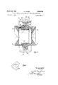
- FIGURE 1 is a vertical sectional view along the spin axis of a gyroscope in accordance with the present invention
- FIGURE 2 is a view similar to FIGURE 1, but showing only the rotor
- FIGURE 3 is a fragmentary elevational view of a portion of the structure of FIGURE 2, as indicated by line 3-3 thereon;
- FIGURE 4 is a sectional view on line 44 in FIG- URE 3.
- FIGURE 5 is a view similar to FIGURE 3, but indicated by line 55 in FIGURE 2.
- FIGURES 1 and 2 One embodiment of the gyro, shown in FIGURES 1 and 2, comprises a central stator supported by a generally tubular shaft 11 having at one end an enlarged, hollow, frusto-conical hub section 12, the outer surface 14 of which forms one of the rotor support bearings in a manner hereinafter described.
- a rotor 13 which coaxially surrounds the stator consists of an annular rim or flywheel 15, formed of brass, gold, or other metal of high specific weight; rim is supported by a pair of flanged hollow cylindrical members 16, 17, made of an aluminum alloy, beryllium or other suitable material to assure maximum dimensional stability.
- Rotor members 16, 17 have respective annular flanges 20, 21 integral therewith and disposed coaxially about shaft 11 with the flanges in abutment and secured together with a ring of screws (one shown at 23) inserted through openings in one of the flanges, and threaded into registering, tapped holes in the other.
- the parting line between flanges 20, 21 lies in a plane substantially perpendicular to the longitudinal axis of shaft 11 and substantially coincides with the lateral plane of symmetry 22 of rotor rim 15.
- Each of the rotor members 16, 17 has a frusto-conical depression 24, 25 in its external end face. Depression 24 coacts with a complementary surface 14 of hub section 12 at the left-hand end of shaft 11 as viewed in FIGURE 1, to provide one conical rotor bearing; another conical rotor bearing is formed at the opposite end of the shaft by coaction of depression 25 with a complementary surface on a hollow frusto-conical hub 27 coaxially fixed to shaft 11 in a manner hereinafter described.
- the removable hub 27 has a thin-wall tubular section 30, which is pressed on or otherwise fitted to an enlarged central segment 11a on shaft 11.
- a plurality of cylindrical pins 31 lock the tubular section 30 in position on the shaft 11.
- a nut 33 threaded onto the right-hand end of shaft 11 bears against an annular flat 32 on removable hub 27 clamping the hub against a shoulder 34 on shaft 11.
- Stator 10 includes a laminated core 35 coaxially fixed to tubular section 30 of hub 27 and having a plurality of radially extending poles 36, 36a.
- a plurality of individual windings 37, 37a are disposed on radial poles 36, 36a of the core in a conventional manner as shown in FIGURE 1.
- Rotor member 17 has a coaxial, cylindrical skirt section 39 having press-fitted therein a tubular hysteresis ring 40 which surrounds stator poles 36, 36a and defines therewith annular air gap 41.
- the magnetic flux lines generated in stator poles 36, 36a by the current flowing through windings 37, 37a react with hysteresis ring 40 in a well-known manner to drive rotor 13 to which it is attached.
- the mating fnisto-conical surfaces 14, 24, 25 and 26 which are machined, ground, and polished to assure a high degree of alignment, preferably make an angle of approximately 55 relative to the spin axis of the gyro. This angle has been found to give maximum bearing efliciency but may be varied over a wide range to satisfy the requirements of a particular installation.
- the clearance between coacting, conical bearing surfaces is held to a minimum while avoiding actual contact therebetween while the rotor is rotating.
- Frusto-conic-al surfaces 14, 24, 25 and 26 are coated with a thin facing of a ceramic material 38, as shown in FIGURE 4, in order to provide a hard bearing surface and reduce wear to a minimum.
- each of the frustoconical faces 24, 25 has a plurality of relatively shallow depressions or pockets 42, 42' of trapezoidal, or other suitable contour cut into the face of the ceramic coating thereof, the depressions being relatively shallow, of the order of .0001" to .00015" deep.
- the depressions or pockets 42, 42' serve to assist in retaining air or gas, which flows through the gap between the co-acting surfaces thus assuring maximum bearing capacity to support the rotor.
- the air or gas filling the gap between the frusto-conical bearing surfaces is drawn into the gap from the surrounding atmosphere by the rotation of the rotor 13, thus providing hydrodynamic gas bearings at both ends of the rotor 13.
- rotor 13 turns at speeds of between l2,000 and 24,000 rpm, although this would be varied, depending upon the diameter of the flywheel ring, the requirements of a particular installation, and the atmosphere in which the gyro is operated.
- the interior 45 of shaft 11, enlarged at one end as at 45a, serves as a conduit for wires 46, 48 leading from an external voltage source to the windings 37, 37a of the stator of the motor.
- ⁇ Wires 46, 48 pass through angu-larly extending connecting passages 47, 49 from the interior of shaft 11 to the stator windings 37, 37a.
- the gyro motor may be constructed and connected for three-phase or single-phase operation, depending upon the specific requirements of a particular motor or gyro installation.
- Rim 15 has an accurately machined central inner surface portion 50, having a press fit on the circumferential outer surfaces of the flanges 20, 21 of rotor members 16, 17, in order to support the rim in accurate alignment with the frusto-conical rotor bearing faces 24, 25.
- a gyroscope assembly comprising a rotor; a stator; and bearing means mounting said rotor and stator in coaxial relationship for relative rotation about the common axis, said bearing means consisting of complementary bearing surfaces on said rotor and stator coaxial with said common axis and coacting to define oppositely tapering frusto-conical bearings at the respective ends of said rotor, said bearing surfaces being formed of a hard ceramic material and constructed and arranged to gen erate therebetween, by reason of relative rotation, a film of gas under pressure serving to lubricate said surfaces.
- a gyroscope assembly comprising: a rotor of substantially circular cross-section; a stator mounted coaxially within the rotor, said stator including a coaxial cylindrical central section having a stator armature coaxially fixed together; a hysteresis tubular ring of hollow cylindrical form fixedly attached to said rotor and coaxially, surrounding said armature at a small radial distance therefrom; bearing surfaces at both longitudinal ends of the rotor, coaxial therewith; bearing surfaces at both ends of the stator, coaxial therewith and complementary to said rotor bearing surfaces, the respective rotor and stator bearing surfaces, coacting to define .therebetween a gap for containment of a thin film of gas under pressure generated between the coacting bearing surfaces for rotatably supporting the rotor with respect to the stator.
- each of said hard-surfaced coatings has a plurality of shallow pockets therein symmetrically spaced about the axis of rotation of the rotor, said pockets being adapted to store gas under pressure, thereby to enhance a gas bearing support between the bearing surfaces of the rotor and the mating bearing surfaces of the stator.
- a gyroscope assembly according to claim 1 including a plurality of shallow pockets between said bearing surfaces symmetrically spaced about said common axis, said pockets being adapted to trap gas under pressure and enhance the load-carrying ability of the gas film lubricating said surfaces.
- a gyroscope assembly according to claim 1, said rotor including a pair of rotor support members of generally hollow cylindrical configuration disposed in coaxial relation and having confronting, radially-outwardly-extending, annular flanges on their adjacent ends, said flanges being detachably fastened in abutment, and an annular r-im coaxially mounted on the outer circumferential edges of said flanges.
- said stator including a tubular shaft having adjacent one end thereof, a ffusto-conical hub portion tapering radially outwardly in the direction of said one end, the outer surface of said hub portion constituting one of said stator bearing surfaces, and a hub member removably secured to the other end of said tubular shaft and having a frusto-conical portion tapering radially outwardly in the direction of said other end of the shaft, the outer surface of the frusto-conical portion of said hub member constituting the other of said stator bearing surfaces.
- said stator including a tubular shaft having adjacent one end thereof a frusto-conical hub portion tapering radially outwardly in the direction of said one end, the outer surfaceof said hub portion constituting one of said stator bearing surfaces; a hub member removably secured to the other end of said tubular shaft and having a frustoconical portion tapering radially outwardly in the direction of said other end of .the shaft, the outer surface of the frusto-conical portion of said hub member constituting the other of said stator bear-ing'surfaces; said rotor including a pair of rotor support members of generally hollow cylindrical configuration coaxiallydisposed about said tubular shaft and having confronting radially outwardly extending annular flanges on their adjacent ends, said flanges being detachably fastened in abutment, the rotor bearing surfaces being formed on the respective ends of said rotor support members remote from said flanges; and an annular rim
Landscapes
- Physics & Mathematics (AREA)
- Engineering & Computer Science (AREA)
- General Physics & Mathematics (AREA)
- Radar, Positioning & Navigation (AREA)
- Remote Sensing (AREA)
- Life Sciences & Earth Sciences (AREA)
- Environmental & Geological Engineering (AREA)
- General Life Sciences & Earth Sciences (AREA)
- Geology (AREA)
- Magnetic Bearings And Hydrostatic Bearings (AREA)
Description
March 29, 1966 B. PARKER 3,242,742
FRUSTO-CONICAL HYDRODYNAMIC GAS BEARING SUPPORTED GYRO Filed Nov. 7, 1961 2 Sheets-Sheet 1 Berna rd Parker INVENTOR.
March 29, 1966 B. PARKER FRUSTO-CONICAL HYDRODYNAMIC GAS BEARING SUPPORTED GYRO Filed Nov. '7, 1961 2 Sheets-Sheet 8 Bernard Parker INVENTOR.
United States Patent 3,242,742 FRUSTO-CONICAL HYDRODYNAMIC GAS BEARING SUPPORTED GYRO Bernard Parker, Teaneck, N.J., assignor to General Precision, Inc., Little Falls, N.J., a corporation of Delaware Filed Nov. 7, 1961, Ser. No. 150,752 10 (Ilairns. (Cl. 74-5) This invention relates to gyroscopes and particularly to gas bearing gyroscopes for use in navigation systems for aircraft, guided missiles, and the like,
A primary object of the invention is to provide a small novel compact gyro having relatively few basic elements which are relatively simple to produce and assemble.
Another object is to provide an improved gyro suitable for installations, in which relatively low cost, a high degree of operating efliciency, and relatively long life are essential requirements.
Another object is to provide a gyroscope capable of high-speed operation for sustained periods.
A further object is to provide a gas-bearing gyroscope which does not require external pressurized gas supplies.
To the fulfillment of these and further objects, the invention contemplates a gyroscope assembly comprising a rotor, a stator, and gas-bearing means mounting said rotor and stator coaxially with respect to one another for relative rotation, said bearing means consisting of complementary frusto-conical bearing surfaces at each end of the rotor and stator disposed with the respective apices of the frusto-conical surfaces oppositely-directed with respect to each other and coaxial with respect to the axis of rotation.
Additional objects of the invention, its advantages, scope and the manner in which it may be practiced will be more fully apparent to persons conversant with the art from the following description of an exemplary embodiment thereof taken in conjunction with the sub-joined claims and the annexed drawings in which like parts are denoted by like reference numerals throughout the several views.
FIGURE 1 is a vertical sectional view along the spin axis of a gyroscope in accordance with the present invention;
FIGURE 2 is a view similar to FIGURE 1, but showing only the rotor;
FIGURE 3 is a fragmentary elevational view of a portion of the structure of FIGURE 2, as indicated by line 3-3 thereon;
FIGURE 4 is a sectional view on line 44 in FIG- URE 3; and
FIGURE 5 is a view similar to FIGURE 3, but indicated by line 55 in FIGURE 2.
One embodiment of the gyro, shown in FIGURES 1 and 2, comprises a central stator supported by a generally tubular shaft 11 having at one end an enlarged, hollow, frusto-conical hub section 12, the outer surface 14 of which forms one of the rotor support bearings in a manner hereinafter described.
A rotor 13 which coaxially surrounds the stator, consists of an annular rim or flywheel 15, formed of brass, gold, or other metal of high specific weight; rim is supported by a pair of flanged hollow cylindrical members 16, 17, made of an aluminum alloy, beryllium or other suitable material to assure maximum dimensional stability. Rotor members 16, 17 have respective annular flanges 20, 21 integral therewith and disposed coaxially about shaft 11 with the flanges in abutment and secured together with a ring of screws (one shown at 23) inserted through openings in one of the flanges, and threaded into registering, tapped holes in the other. The parting line between flanges 20, 21 lies in a plane substantially perpendicular to the longitudinal axis of shaft 11 and substantially coincides with the lateral plane of symmetry 22 of rotor rim 15.
Each of the rotor members 16, 17 has a frusto- conical depression 24, 25 in its external end face. Depression 24 coacts with a complementary surface 14 of hub section 12 at the left-hand end of shaft 11 as viewed in FIGURE 1, to provide one conical rotor bearing; another conical rotor bearing is formed at the opposite end of the shaft by coaction of depression 25 with a complementary surface on a hollow frusto-conical hub 27 coaxially fixed to shaft 11 in a manner hereinafter described.
The removable hub 27 has a thin-wall tubular section 30, which is pressed on or otherwise fitted to an enlarged central segment 11a on shaft 11. A plurality of cylindrical pins 31 lock the tubular section 30 in position on the shaft 11.
A nut 33 threaded onto the right-hand end of shaft 11 bears against an annular flat 32 on removable hub 27 clamping the hub against a shoulder 34 on shaft 11.
Stator 10 includes a laminated core 35 coaxially fixed to tubular section 30 of hub 27 and having a plurality of radially extending poles 36, 36a. A plurality of individual windings 37, 37a are disposed on radial poles 36, 36a of the core in a conventional manner as shown in FIGURE 1.
The mating fnisto- conical surfaces 14, 24, 25 and 26 which are machined, ground, and polished to assure a high degree of alignment, preferably make an angle of approximately 55 relative to the spin axis of the gyro. This angle has been found to give maximum bearing efliciency but may be varied over a wide range to satisfy the requirements of a particular installation. The clearance between coacting, conical bearing surfaces is held to a minimum while avoiding actual contact therebetween while the rotor is rotating.
Frusto-conic- al surfaces 14, 24, 25 and 26 are coated with a thin facing of a ceramic material 38, as shown in FIGURE 4, in order to provide a hard bearing surface and reduce wear to a minimum.
As shown in FIGURES 3 and 5, each of the frustoconical faces 24, 25 has a plurality of relatively shallow depressions or pockets 42, 42' of trapezoidal, or other suitable contour cut into the face of the ceramic coating thereof, the depressions being relatively shallow, of the order of .0001" to .00015" deep. The depressions or pockets 42, 42' serve to assist in retaining air or gas, which flows through the gap between the co-acting surfaces thus assuring maximum bearing capacity to support the rotor. In the illustrated embodiment there are six equally-spaced pockets 42, 42' in each bearing surface of the rotor; however, a greater or lesser number may be used depending on the diameter of the bearing surfaces. The air or gas filling the gap between the frusto-conical bearing surfaces is drawn into the gap from the surrounding atmosphere by the rotation of the rotor 13, thus providing hydrodynamic gas bearings at both ends of the rotor 13.
In normal operation, rotor 13 turns at speeds of between l2,000 and 24,000 rpm, although this would be varied, depending upon the diameter of the flywheel ring, the requirements of a particular installation, and the atmosphere in which the gyro is operated.
The interior 45 of shaft 11, enlarged at one end as at 45a, serves as a conduit for wires 46, 48 leading from an external voltage source to the windings 37, 37a of the stator of the motor. \ Wires 46, 48 pass through angu-larly extending connecting passages 47, 49 from the interior of shaft 11 to the stator windings 37, 37a.
The gyro motor may be constructed and connected for three-phase or single-phase operation, depending upon the specific requirements of a particular motor or gyro installation.
Rim 15 has an accurately machined central inner surface portion 50, having a press fit on the circumferential outer surfaces of the flanges 20, 21 of rotor members 16, 17, in order to support the rim in accurate alignment with the frusto-conical rotor bearing faces 24, 25.
Although but one preferred embodiment of the invention has been illustrated and described, it will be apparent to those skilled in the art that many changes may be made in the preferred frusto-conical gas bearing supported gyro as illustrated and described, without departing from the spirit and scope of this invention. Accordingly, this invention is to be considered as being limited only by the following claims appended hereto.
What is claimed is:
1. A gyroscope assembly comprising a rotor; a stator; and bearing means mounting said rotor and stator in coaxial relationship for relative rotation about the common axis, said bearing means consisting of complementary bearing surfaces on said rotor and stator coaxial with said common axis and coacting to define oppositely tapering frusto-conical bearings at the respective ends of said rotor, said bearing surfaces being formed of a hard ceramic material and constructed and arranged to gen erate therebetween, by reason of relative rotation, a film of gas under pressure serving to lubricate said surfaces.
2. A gyroscope assembly comprising: a rotor of substantially circular cross-section; a stator mounted coaxially within the rotor, said stator including a coaxial cylindrical central section having a stator armature coaxially fixed together; a hysteresis tubular ring of hollow cylindrical form fixedly attached to said rotor and coaxially, surrounding said armature at a small radial distance therefrom; bearing surfaces at both longitudinal ends of the rotor, coaxial therewith; bearing surfaces at both ends of the stator, coaxial therewith and complementary to said rotor bearing surfaces, the respective rotor and stator bearing surfaces, coacting to define .therebetween a gap for containment of a thin film of gas under pressure generated between the coacting bearing surfaces for rotatably supporting the rotor with respect to the stator.
3. A gyroscope assembly according to claim 2, where in said bearing surfaces are of frusto-conical form, with apices oppositely directed at opposite ends of the rotor and stator assembly, each frusto-conical bearing surface of both rotor and stator having a hard-surfaced coating thereon.
4. A gyroscope assembly according to claim 3, wherein each of said hard-surfaced coatings has a plurality of shallow pockets therein symmetrically spaced about the axis of rotation of the rotor, said pockets being adapted to store gas under pressure, thereby to enhance a gas bearing support between the bearing surfaces of the rotor and the mating bearing surfaces of the stator.
5. A gyroscope assembly according to claim 1 including a plurality of shallow pockets between said bearing surfaces symmetrically spaced about said common axis, said pockets being adapted to trap gas under pressure and enhance the load-carrying ability of the gas film lubricating said surfaces.
6. A gyroscope assembly according to claim 5 wherein the radial dimension of each of said pockets is greater at one limit of its circumferential extent than at the other. 7
7. A gyroscope assembly according to claim 1, said rotor including a pair of rotor support members of generally hollow cylindrical configuration disposed in coaxial relation and having confronting, radially-outwardly-extending, annular flanges on their adjacent ends, said flanges being detachably fastened in abutment, and an annular r-im coaxially mounted on the outer circumferential edges of said flanges.
8. A gyroscope assembly according to claim 7 wherein the bearing surfaces on said rotor are formed on the re spective ends of said rotor support members remote from said flanges.
9. A gyroscope assembly accord-ing to claim 8, said stator including a tubular shaft having adjacent one end thereof, a ffusto-conical hub portion tapering radially outwardly in the direction of said one end, the outer surface of said hub portion constituting one of said stator bearing surfaces, and a hub member removably secured to the other end of said tubular shaft and having a frusto-conical portion tapering radially outwardly in the direction of said other end of the shaft, the outer surface of the frusto-conical portion of said hub member constituting the other of said stator bearing surfaces.
10. A gyroscope assembly according to claim 2, said stator including a tubular shaft having adjacent one end thereof a frusto-conical hub portion tapering radially outwardly in the direction of said one end, the outer surfaceof said hub portion constituting one of said stator bearing surfaces; a hub member removably secured to the other end of said tubular shaft and having a frustoconical portion tapering radially outwardly in the direction of said other end of .the shaft, the outer surface of the frusto-conical portion of said hub member constituting the other of said stator bear-ing'surfaces; said rotor including a pair of rotor support members of generally hollow cylindrical configuration coaxiallydisposed about said tubular shaft and having confronting radially outwardly extending annular flanges on their adjacent ends, said flanges being detachably fastened in abutment, the rotor bearing surfaces being formed on the respective ends of said rotor support members remote from said flanges; and an annular rim coaxially mounted on the outer circumferential edges of said flanges.
References Cited by the Examiner UNITED STATES PATENTS 2,937,804 5/ 1960 Reiner et al 745.7 X 3,027,471 3/ 1962 Burgwin et a1. 74-5 .7 X 3,043,635 7/1962 Bard 308-9 3,048,043 8/1962 Slater et al 74-5 3,071,421 1/1963 Jones et al. 74-5 X MILTON KAUFMAN, Primary Examiner. BROUGHTON G. DURHAM, Examiner.
T. W. SHEAR, Assistant Examiner.
Claims (1)
1. A GYROSCOPE ASSEMBLY COMPRISING A ROTOR; A STATOR; AND BEARING MEANS MOUNTING SAID ROTOR AND STATOR IN COAXIAL RELATIONSHIP FOR RELATIVE ROTATION ABOUT THE COMMON AXIS, SAID BEARING MEANS CONSISTING OF COMPLEMENTARY BEARING SURFACES ON SAID ROTOR AND STATOR COAXIAL WITH SAID COMMON AXIS AND COACTING TO DEFINE OPPOSITELY TAPERING FRUSTO-CONICAL BEARINGS AT THE RESPECTIVE ENDS OF SAID ROTOR, SAID BEARING SURFACES, BEING FORMED OF A HARD CERAMIC MATERIAL AND CONSTRUCTED AND ARRANGED TO GENERATE THEREBETWEEN, BY REASON OF RELATIVE ROTATION, A FILM OF GAS UNDER PRESSURE SERVING TO LUBRICATE SAID SURFACES.
Publications (1)
| Publication Number | Publication Date |
|---|---|
| US3242742A true US3242742A (en) | 1966-03-29 |
Family
ID=3458073
Family Applications (1)
| Application Number | Title | Priority Date | Filing Date |
|---|---|---|---|
| US3242742D Expired - Lifetime US3242742A (en) | Frustoxconical h hydrodynamic gas bearing supported gyro |
Country Status (1)
| Country | Link |
|---|---|
| US (1) | US3242742A (en) |
Cited By (12)
| Publication number | Priority date | Publication date | Assignee | Title |
|---|---|---|---|---|
| US3362231A (en) * | 1965-09-10 | 1968-01-09 | Honeywell Inc | Control apparatus |
| US3416300A (en) * | 1966-04-06 | 1968-12-17 | Schenkel Erwin | Spinning and twisting apparatus |
| US3431786A (en) * | 1965-10-07 | 1969-03-11 | Teldix Luftfahrt Ausruestung | Symmetrical gyroscope |
| US3498144A (en) * | 1962-03-21 | 1970-03-03 | Singer General Precision | Stable two-axis case rotating gyroscopes |
| US4140592A (en) * | 1978-03-30 | 1979-02-20 | The United States Of America As Represented By The Secretary Of The Air Force | Gas bearing surface coating |
| US4466299A (en) * | 1964-11-23 | 1984-08-21 | General Motors Corporation | Gyro bearing assembly |
| US20090100950A1 (en) * | 2007-10-19 | 2009-04-23 | Yoshio Sato | Pressure application driving unit of welding gun |
| US20100126302A1 (en) * | 2007-05-17 | 2010-05-27 | Jonathan James Robert Hilton | High speed flywheel containment |
| US8919213B2 (en) | 2012-05-21 | 2014-12-30 | Honeywell International Inc. | Control moment gyroscopes including rotors having radially-compliant spokes and methods for the manufacture thereof |
| US9354079B2 (en) | 2012-05-21 | 2016-05-31 | Honeywell International Inc. | Control moment gyroscopes including torsionally-stiff spoked rotors and methods for the manufacture thereof |
| RU2589939C1 (en) * | 2015-04-30 | 2016-07-10 | Евгений Алексеевич Артюхов | Electromagnetic gyroscope |
| US9765816B2 (en) | 2015-09-14 | 2017-09-19 | The Boeing Company | Hydrodynamic bearing with compensated hydrostatic phase |
Citations (5)
| Publication number | Priority date | Publication date | Assignee | Title |
|---|---|---|---|---|
| US2937804A (en) * | 1956-06-29 | 1960-05-24 | Reiner Markus | Apparatus for the compression of gases |
| US3027471A (en) * | 1960-04-04 | 1962-03-27 | Honeywell Regulator Co | Gas bearing spin motor |
| US3043635A (en) * | 1960-02-01 | 1962-07-10 | Chrysler Corp | Air bearings |
| US3048043A (en) * | 1954-09-01 | 1962-08-07 | North American Aviation Inc | Gas bearing gyroscope |
| US3071421A (en) * | 1958-09-15 | 1963-01-01 | Northrop Corp | Compensated pre-loaded bearing |
-
0
- US US3242742D patent/US3242742A/en not_active Expired - Lifetime
Patent Citations (5)
| Publication number | Priority date | Publication date | Assignee | Title |
|---|---|---|---|---|
| US3048043A (en) * | 1954-09-01 | 1962-08-07 | North American Aviation Inc | Gas bearing gyroscope |
| US2937804A (en) * | 1956-06-29 | 1960-05-24 | Reiner Markus | Apparatus for the compression of gases |
| US3071421A (en) * | 1958-09-15 | 1963-01-01 | Northrop Corp | Compensated pre-loaded bearing |
| US3043635A (en) * | 1960-02-01 | 1962-07-10 | Chrysler Corp | Air bearings |
| US3027471A (en) * | 1960-04-04 | 1962-03-27 | Honeywell Regulator Co | Gas bearing spin motor |
Cited By (13)
| Publication number | Priority date | Publication date | Assignee | Title |
|---|---|---|---|---|
| US3498144A (en) * | 1962-03-21 | 1970-03-03 | Singer General Precision | Stable two-axis case rotating gyroscopes |
| US4466299A (en) * | 1964-11-23 | 1984-08-21 | General Motors Corporation | Gyro bearing assembly |
| US3362231A (en) * | 1965-09-10 | 1968-01-09 | Honeywell Inc | Control apparatus |
| US3431786A (en) * | 1965-10-07 | 1969-03-11 | Teldix Luftfahrt Ausruestung | Symmetrical gyroscope |
| US3416300A (en) * | 1966-04-06 | 1968-12-17 | Schenkel Erwin | Spinning and twisting apparatus |
| US4140592A (en) * | 1978-03-30 | 1979-02-20 | The United States Of America As Represented By The Secretary Of The Air Force | Gas bearing surface coating |
| US8234953B2 (en) * | 2007-05-17 | 2012-08-07 | Flybrid Systems Llp | High speed flywheel containment |
| US20100126302A1 (en) * | 2007-05-17 | 2010-05-27 | Jonathan James Robert Hilton | High speed flywheel containment |
| US20090100950A1 (en) * | 2007-10-19 | 2009-04-23 | Yoshio Sato | Pressure application driving unit of welding gun |
| US8919213B2 (en) | 2012-05-21 | 2014-12-30 | Honeywell International Inc. | Control moment gyroscopes including rotors having radially-compliant spokes and methods for the manufacture thereof |
| US9354079B2 (en) | 2012-05-21 | 2016-05-31 | Honeywell International Inc. | Control moment gyroscopes including torsionally-stiff spoked rotors and methods for the manufacture thereof |
| RU2589939C1 (en) * | 2015-04-30 | 2016-07-10 | Евгений Алексеевич Артюхов | Electromagnetic gyroscope |
| US9765816B2 (en) | 2015-09-14 | 2017-09-19 | The Boeing Company | Hydrodynamic bearing with compensated hydrostatic phase |
Similar Documents
| Publication | Publication Date | Title |
|---|---|---|
| US3242742A (en) | Frustoxconical h hydrodynamic gas bearing supported gyro | |
| US3107310A (en) | Magnetic coupling having a magnetic bearing | |
| US4337406A (en) | Bearing-less remotely journalled dynamo electric machine, particularly alternator for combination with a gas turbine | |
| US3513339A (en) | Electric motor construction | |
| US5751085A (en) | Axial gap type electric motor with dynamic pressure air bearing | |
| US2104707A (en) | Electric generator | |
| US3741034A (en) | Inertial energy storage apparatus | |
| US4286187A (en) | Bearingless generator and rotary machine combination | |
| RU170274U1 (en) | MAGNET BEARING | |
| JPS5917019A (en) | Rotary body supporter | |
| US3016274A (en) | Magnetically spaced ball bearing | |
| US5101130A (en) | Magnetic thrust bearings | |
| US3438270A (en) | Two-axis torquer | |
| US3322986A (en) | Gyroscopic rotor | |
| US2581965A (en) | Rate gyroscope | |
| FR1271654A (en) | Device for mounting the rotor of a rotating machine | |
| US3614180A (en) | Bearing arrangement for a rotor | |
| JPS5972956A (en) | Light deflecting motor | |
| CN104697509B (en) | A kind of magnetically suspended gyroscope of seven passages magnetic circuit decoupling | |
| US2683830A (en) | Dynamoelectric machine stator construction | |
| US2193531A (en) | High speed alternating current | |
| CN111102292A (en) | Magnetic suspension bearing assembly, outer rotor motor assembly and motor | |
| US3240075A (en) | Drag cup damper means for gyroscopes | |
| US2438621A (en) | Electric motor structure for gyroscopes | |
| US3192422A (en) | Spiral bearing support |