US320274A - Tebeitoey - Google Patents
Tebeitoey Download PDFInfo
- Publication number
- US320274A US320274A US320274DA US320274A US 320274 A US320274 A US 320274A US 320274D A US320274D A US 320274DA US 320274 A US320274 A US 320274A
- Authority
- US
- United States
- Prior art keywords
- oil
- pan
- tank
- filtering material
- pipe
- Prior art date
- Legal status (The legal status is an assumption and is not a legal conclusion. Google has not performed a legal analysis and makes no representation as to the accuracy of the status listed.)
- Expired - Lifetime
Links
- 238000001914 filtration Methods 0.000 description 10
- 239000000463 material Substances 0.000 description 9
- 239000012530 fluid Substances 0.000 description 3
- XLYOFNOQVPJJNP-UHFFFAOYSA-N water Substances O XLYOFNOQVPJJNP-UHFFFAOYSA-N 0.000 description 3
- 238000010438 heat treatment Methods 0.000 description 2
- 238000005192 partition Methods 0.000 description 2
- 239000011362 coarse particle Substances 0.000 description 1
- 238000010276 construction Methods 0.000 description 1
- 239000011521 glass Substances 0.000 description 1
- 230000001050 lubricating effect Effects 0.000 description 1
- 239000002184 metal Substances 0.000 description 1
- 235000011837 pasties Nutrition 0.000 description 1
- 239000002699 waste material Substances 0.000 description 1
- 239000002351 wastewater Substances 0.000 description 1
Images
Classifications
-
- B—PERFORMING OPERATIONS; TRANSPORTING
- B01—PHYSICAL OR CHEMICAL PROCESSES OR APPARATUS IN GENERAL
- B01D—SEPARATION
- B01D35/00—Filtering devices having features not specifically covered by groups B01D24/00 - B01D33/00, or for applications not specifically covered by groups B01D24/00 - B01D33/00; Auxiliary devices for filtration; Filter housing constructions
- B01D35/18—Heating or cooling the filters
Definitions
- OIL FILTER w m w W M w W m e I I. T. m W M A J N. PETERS. Pholo-Lnhographnr, Wnhingwn, DA;
- the object of this invention is to cleanse oil which has been used for lubricating purposes, both from insoluble foreign matter and from surplus water at one continuous operation.
- A represents a tank provided with a dischargelaucet, M, and with a glass gage, L, by means of which latter theheight and condition of the filtered oil in the tank may be seen.
- B is a coarse strainer into which the dirty oilis placed. In passing through this strainer the oil is relieved of coarse particles of dirt.
- G is the heating-pan, provided with a coil of pipe, G, into which steam enters at D, and from which it discharges at H, after having imparted most of its heat through the pipe (2 directly to the oil, which is in contact with the pipe in pan G, having descended thereto through the strainer B.
- the heating will be continued in the pan G until any water which may be in the oil is driven off, thereby producing two effectsfirst, the water and light fluids being expanded into vapor and dissipated, the remaining product is a heavier oil possessed of more body, and consequently more valuable for future use; second, the watery fluids being expelled leaves much waste matter to be filtered out, which would otherwise have been held in solution, and would have thus passed through the filter with the oil to deteriorate it; therefore, by first heating the oil to drive ofi'the lighter fluids the subsequent filtration is aided in producing better oil.
- F is a stopcock provided with a handle, E, by means of which the heated oil may be passed into the first filtering-pan, J.
- P represents a series of screens of perforated sheet metal or wireeloth, set a little inclined alternately in opposite directions to screen out coarse matter from the oil.
- These screens are each provided with a series of partitions, L, standingacross the path of the oil to prevent its flowing too quickly down the inclines, to
- pan J represents a series of pans perforated through their bottoms and filled with filtering material of any suitable character. These pans are provided with lugs K, each to support the pan above. Thelowcr pan rests upon lugs K, fixed to the tank A. Below the lower pan the tank accumulates the oil which passes through the filters and holds it for use.
- the pans J are duplicates of each other and i1lterchangeable, so that when the filtering material in the top pan becomes foul the pan may be emptied and refilled with clean filtering material and placed below the others to do the finishing while it is fresh and clean. 13y thus rotating each pan is caused to do all the different grades of service from best to poorest untilit is too foul for further use, thus economizing filtering material.
- I is an airtube for the reservoir-chamber, topermit ingress of air while oil is being withdrawn by the faucet M.
- the heating-pan G being placed within the tank A distributes heat through all the liltering material, thereby keeping the mass sufficientlyfluidto assist the oil to flow. As the top is not sealed in any manner, the vapor from the waste water will find its way out without special provision therefor, yet an exit might be provided, if found necessary.
- strainer B being placed above theheat pipe very thick pasty oil may be assisted by the heat to flow into the filter, thereby saving what would otherwise be lost.
Landscapes
- Chemical & Material Sciences (AREA)
- Chemical Kinetics & Catalysis (AREA)
- Filtering Materials (AREA)
Description
(No Model.)
D. S. NEIMAN.
OIL FILTER w m w W M w W m e I I. T. m W M A J N. PETERS. Pholo-Lnhographnr, Wnhingwn, DA;
UNTTED STATES PATTLNT Q Tr ce.
DANIEL S. NEIMAN, OF FARGO, DAKOTA TERRITORY.
OIL-FILTER.
t'iPEQIFTCATION forming part of Letters Patent No. 320,274, dated June 16, 1885.
(No model.)
To all whom it may concern:
Be it known that I, DANIEL S. NEIMAN, a citizen of the United States, residing at Fargo, in the county of Cass, Dakota Territory, have invented certain new and useful Improvements in OilFiltcrs, of which the following is a description.
The object of this invention is to cleanse oil which has been used for lubricating purposes, both from insoluble foreign matter and from surplus water at one continuous operation.
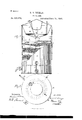
To this end my invention consists in the construction and combination of parts forming a filter, hereinafter described and claimed, reference being had to the accompanying drawings, in which Figure l is a side elevation of a filter according to my invention, partly broken away to show the interior; and Fig. 2 is a plan view of the same.
A represents a tank provided with a dischargelaucet, M, and with a glass gage, L, by means of which latter theheight and condition of the filtered oil in the tank may be seen.
B is a coarse strainer into which the dirty oilis placed. In passing through this strainer the oil is relieved of coarse particles of dirt.
G is the heating-pan, provided with a coil of pipe, G, into which steam enters at D, and from which it discharges at H, after having imparted most of its heat through the pipe (2 directly to the oil, which is in contact with the pipe in pan G, having descended thereto through the strainer B. The heating will be continued in the pan G until any water which may be in the oil is driven off, thereby producing two effectsfirst, the water and light fluids being expanded into vapor and dissipated, the remaining product is a heavier oil possessed of more body, and consequently more valuable for future use; second, the watery fluids being expelled leaves much waste matter to be filtered out, which would otherwise have been held in solution, and would have thus passed through the filter with the oil to deteriorate it; therefore, by first heating the oil to drive ofi'the lighter fluids the subsequent filtration is aided in producing better oil.
F is a stopcock provided with a handle, E, by means of which the heated oil may be passed into the first filtering-pan, J.
P represents a series of screens of perforated sheet metal or wireeloth, set a little inclined alternately in opposite directions to screen out coarse matter from the oil. These screens are each provided with a series of partitions, L, standingacross the path of the oil to prevent its flowing too quickly down the inclines, to
.insnre the lodgement of all coarse foreign matter in the screens before entering the filtering material, because the screens may be readily removed to be washed. Thesescreens maybe at any time removed and substituted by others or quickly rinsed and returned.
J represents a series of pans perforated through their bottoms and filled with filtering material of any suitable character. These pans are provided with lugs K, each to support the pan above. Thelowcr pan rests upon lugs K, fixed to the tank A. Below the lower pan the tank accumulates the oil which passes through the filters and holds it for use. The pans J are duplicates of each other and i1lterchangeable, so that when the filtering material in the top pan becomes foul the pan may be emptied and refilled with clean filtering material and placed below the others to do the finishing while it is fresh and clean. 13y thus rotating each pan is caused to do all the different grades of service from best to poorest untilit is too foul for further use, thus economizing filtering material.
I is an airtube for the reservoir-chamber, topermit ingress of air while oil is being withdrawn by the faucet M. The heating-pan G being placed within the tank A distributes heat through all the liltering material, thereby keeping the mass sufficientlyfluidto assist the oil to flow. As the top is not sealed in any manner, the vapor from the waste water will find its way out without special provision therefor, yet an exit might be provided, if found necessary.
The strainer B being placed above theheat pipe very thick pasty oil may be assisted by the heat to flow into the filter, thereby saving what would otherwise be lost.
\Vhat I claim as my invention, and desire to secure by Letters Patent, is-
1. The combination, with a tank and filtering material therein, of a series ofstrainers, P, placed one above another in the tank, above the filtering materia1, and the partitions L in the pan, of a strainer located above the therein, the strainers being slanted alternately steam-pipe within the tank, as shown and dein opposite directions, as and for the purpose seribcd.
specified.
- 2. The conlbinatimi, with a tank, filtering material therein a pan within the tanlgabove the filtering material, and a coiled steam-pipe DANIEL S. NEIMAN. \Vitnesses:
CHARLES H. J. Buss, GEORGE W. BIRD.
Publications (1)
| Publication Number | Publication Date |
|---|---|
| US320274A true US320274A (en) | 1885-06-16 |
Family
ID=2389415
Family Applications (1)
| Application Number | Title | Priority Date | Filing Date |
|---|---|---|---|
| US320274D Expired - Lifetime US320274A (en) | Tebeitoey |
Country Status (1)
| Country | Link |
|---|---|
| US (1) | US320274A (en) |
-
0
- US US320274D patent/US320274A/en not_active Expired - Lifetime
Similar Documents
| Publication | Publication Date | Title |
|---|---|---|
| US3473663A (en) | Multiple filter element fluid purifying system | |
| US320274A (en) | Tebeitoey | |
| US2155960A (en) | Scum remover | |
| DE397566C (en) | Device for warming up and cleaning the fuel in motor vehicle engines | |
| US1017100A (en) | Oil-filter. | |
| US911388A (en) | Oil filter and purifier. | |
| US246003A (en) | Fourths to william unfug | |
| US273084A (en) | Feed-water heater | |
| US140719A (en) | Improvement in heaters and filters | |
| US458075A (en) | Oil-filter | |
| US326580A (en) | And john d | |
| US597222A (en) | Filtering device | |
| US1725845A (en) | Apparatus for purifying waste lubricating oil | |
| US516674A (en) | And daniel b | |
| US631571A (en) | Feed-water purifier. | |
| US171328A (en) | Improvement in apparatus for treating tallow, oils | |
| US536367A (en) | Oil-purifier | |
| US493644A (en) | Oil-filter | |
| US385769A (en) | Feed-water heater and purifier | |
| US724661A (en) | Feed-water heater and filter. | |
| US840381A (en) | Oil-filter. | |
| US504434A (en) | Edward peck hunt | |
| US337459A (en) | Apparatus for cleaning oil | |
| US1204071A (en) | Filter. | |
| US740957A (en) | Oil-filter. |