US3173457A - Method of and apparatus for pressure charging aerosol dispensers with push buttons attached - Google Patents
Method of and apparatus for pressure charging aerosol dispensers with push buttons attached Download PDFInfo
- Publication number
- US3173457A US3173457A US115589A US11558961A US3173457A US 3173457 A US3173457 A US 3173457A US 115589 A US115589 A US 115589A US 11558961 A US11558961 A US 11558961A US 3173457 A US3173457 A US 3173457A
- Authority
- US
- United States
- Prior art keywords
- valve
- propellant
- adapter
- chamber
- gasket
- Prior art date
- Legal status (The legal status is an assumption and is not a legal conclusion. Google has not performed a legal analysis and makes no representation as to the accuracy of the status listed.)
- Expired - Lifetime
Links
- 238000000034 method Methods 0.000 title description 11
- 239000004479 aerosol dispenser Substances 0.000 title description 5
- 238000007789 sealing Methods 0.000 claims description 36
- 239000000443 aerosol Substances 0.000 claims description 17
- 239000003380 propellant Substances 0.000 description 39
- 239000004480 active ingredient Substances 0.000 description 4
- 239000000945 filler Substances 0.000 description 4
- 238000012856 packing Methods 0.000 description 4
- 230000000694 effects Effects 0.000 description 3
- 238000010276 construction Methods 0.000 description 2
- 230000000994 depressogenic effect Effects 0.000 description 2
- 239000000463 material Substances 0.000 description 2
- 238000003825 pressing Methods 0.000 description 2
- 230000006835 compression Effects 0.000 description 1
- 238000007906 compression Methods 0.000 description 1
- 101150038956 cup-4 gene Proteins 0.000 description 1
- 230000000881 depressing effect Effects 0.000 description 1
- 239000007788 liquid Substances 0.000 description 1
- 239000002184 metal Substances 0.000 description 1
- 230000000284 resting effect Effects 0.000 description 1
Images


Classifications
-
- B—PERFORMING OPERATIONS; TRANSPORTING
- B65—CONVEYING; PACKING; STORING; HANDLING THIN OR FILAMENTARY MATERIAL
- B65B—MACHINES, APPARATUS OR DEVICES FOR, OR METHODS OF, PACKAGING ARTICLES OR MATERIALS; UNPACKING
- B65B31/00—Packaging articles or materials under special atmospheric or gaseous conditions; Adding propellants to aerosol containers
- B65B31/003—Adding propellants in fluid form to aerosol containers
Definitions
- An aerosol dispensing package commonly comprises a metal can body having a top opening sealed by a mounting cup on which is supported a manually operable valve having a tubular valve stem surmounted by'a push button by means of which the valve stem may be depressed to open the valve and permit the discharge of the contents of the can through an outlet orifice in the push button.
- US. Patent No. 2,631,814 is illustrative of this general type of package.
- the can contains a so-called active ingredient, which it is the primary purpose to dispense, together with a pressurized propellant.
- the word can, as hereinafter used, should be construed to cover containers of all kinds in which aerosol material is packaged.
- the term push button will also apply to a valve operating cap sometimes used in place of the conventional push button.
- One common method of filling and charging aerosol dispensing packages is to fill the can body with the desired quantity of active ingredient, then permanently apply the mounting cup with the valve thereon, then position the can, without attached push button, in a propellant charging machine which forces the propellant through and around the valve stem into the cam body while the valve associated with said valve stem is held open.
- the propellant is normally supplied through a so-called filler head which forms part and parcel of a charging machine of complicated character, so constituted as to act directly upon the valve stem to effect unsealing of the valve and, after the charging operation is completed, the valve is permitted to close and the charged can removed from the machine.
- an adapter that may be used with any type of apparatus or machine capable of applying pressure, whreeby the utilization of a complicated charging machine with filler head is rendered unnecessary and also to provide an adapter wherein the chamber through which the propellant is introduced into the can has a more effective seal than that produced in the adapter of my prior application, so as to preclude leakage at this ponit and at the same time compensate for variations in size of the can and the parts thereof.
- the adapter that it may be mounted on any appropriate mechanism which will simply raise or lower the adapter and apply to it sufficient pressure to force it against the can or, if desired, the
- adapter may be mounted in fixed position and the can elevated against it with sufficient force to actuate the parts of such adapter.
- the adapter is provided therein with a chamber in which the valve stem, with attached push button, is adapted to be received.
- a sealing ring into which a portion of the container extends and is adapted to be gripped by said sealing ring to form therewith an impervious seal when pressure is applied to the sealing ring through a leverage system.
- the levers of this system so multiply the power applied to the adapter as to impart to said sealing ring abundant pressure, without placing undue strain on the container, to preclude leakage of the character referred to. This is an important feature of this invention.
- the invention is directed, as in the case of my aforesaid prior application, to the steps of introducing an active ingredient into the can, sealing the can with a mounting cup on which is supported a valve having a valve stem to which a push button having a discharge orifice is attached, then enclosing the push button, valve stem and a portion of the can adjacent the valve stem, within a sealed chamber, introducing propellant under pressure into said chamber while the valve of the can is held open, so that propellant may flow through the push button and valve stem and through the valve into the interior of the can, then shutting off the flow of propellant into said chamber, permitting the valve to close, and separating the chamber and can.
- Various forms of apparatus may be employed in carrying out this method.
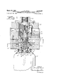
- FIG. 1 is a central section through the adapter of this invention showing the parts thereof in the inactive positions.
- FIG. 2 is a horizontal section taken substantially along the broken line 2--2 of FIG. 1.
- FIG. 3 is a vertical section taken substantially along the line 33 of FIG. 2.
- FIG. 4 is an exploded view of three different associated parts of the structure shown in the remaining figures.
- FIG. 5 is a plan view of the lower part of the lower section of the adapter with all movable operating parts removed.
- FIG. 6 is a section on the line 6-6 of FIG. 5.
- 1 indicates a conventional can body having a top opening, the margin of which is curled as at 2 to receive in sealing relation the marginal inverted channel 3 of a mounting cup 4.
- This cup has a central boss 5 in which is supported any appropriate form of valve having an upstanding valve stem 6.
- Push button B provided therein with the usual expansion chamber and outlet orifice 7, is mounted on the valve stem so that material flowing from the can through the valve stem passes through the push button and is discharged through said orifice.
- the adapter of the present invention comprises a body having an upper section 8 and a relatively movable lower section 9, the latter of which is made in two parts, namely, an upper part 10 and a lower part 11. These two parts are rigidly secured together by a plurality of screws 12,
- the lower surface 13 of the part 11 forms an abutment which, in the preferred form of the invention, is adapted to rest upon the marginal portion of the mounting cup, as shown in FIG. 1, and said lower part is also provided centrally with a depending boss 14 which projects downwardly into the interior of the mounting cup and may, if desired, actually engage with the base of the cup.
- the upper section 8 and both parts 16 and 11 of the lower section are provided with a cylindrical axial bore 15 which extends uninterruptedly for the full height of the adapter but near its lower end and within the boss 14, this bore is flared inwardly at 16 to provide a seat for a sealing ring or gasket 17, there being four spaced apart slots 18 leading from said seat to the bottom of the boss as shown best in FIG. 3.
- a sealing sleeve 19 which extends from near the top of the upper section 8 to a point immediately above the seat 16 in the boss 14.
- the lower end of said sleeve is internally chamfered at 20 so that, when said sleeve is forced downwardly, it will engage the sealing ring 17 and compress the same to form a seal between the boss 14 of the section 11 and the boss 5 of the mounting cup.
- the sealing sleeve is forced downwardly to produce this seal in the mechanism next to be described.
- Sealing sleeve 19 is provided near its lower end with axially spaced apart flanges forming between them an annular groove 21.
- trunnions 22 shown best in FIG. 2.
- These trunnions are mounted onsecondary levers 2 3 which are fulcrumed on pins 24 (FIG. 2) mounted in slots 25 (FIGS. 5 an d 6) formed in the lower part 11 of the lower section 9.
- Each of the levers 23 extends substantially tangentially of the groove 21 (FIG. 2) and carries at its outer end a trunnion 26 which overlies one end of a primary lever 27 (FIGS. 2 and 3) mounted in a slot 28 in the lower part 11 (FIGS.
- each primary lever 27 is engaged by the lower end of a power pin 30.
- This pin extends vertically through the upper section 8 and the upper part 10 of the lower section, as shown best in FIG. 3. It is secured to the upper section 8 by the overlying flange of a fitting 31 (FIG. 1), so that it is locked against axial movement with respect to said upper section 8 while being permitted to slide freely through the upper part 10 of the lower section 9.
- the upper section 8 telescopes into the part 10 of the lower section and is adapted for movement relative to t the latter by limiting studs 32 (FIG. 1), three of which are employed in this construction, being equally spaced in annular relation about the adapter. These studs permit the upper section to be raised and lowered relative to the lower section, but secure such sections to one another for bodily raising and lowering movement. Said sections are, however, normally maintained in the relatively distended relation shown in FIG. 1 by springs 33 mounted in pockets of the upper section and acting at their lower ends upon pins 34 which bear upon the outer ends of the levers 23. The springs 33 thus normally hold the upper and lower sections in spaced relation, with the spacing limited by the limiting studs 32, while permitting said sections to be brought into closer spacing by pressure on the upper section, transmitted through the fitting 31 while the lower section is resting upon the can 1.
- a plug 36 Closely seated within the upper end of the sealing sleeve 19 is a plug 36, locked to the sleeve by a screw 37.
- This plug is in the form of an inverted hollow cup provided intermediate its height with a packing 38 and the lower end of the wall of which cup is provided with cutouts 39, so that said lower end is in effect castellated, as clearly shown in FIG. 4.
- These cut-outs register with an intake passage 40 through which propellant under pressure may enter the interior of the sealing sleeve 19.
- the lower end of the plug 36 seats upon the upper edge of a valve seat member 41 having an exterior packing and provided with a valve seat 42. From this valve seat 42, passages 43 lead to the exterior surface of the valve seat member 41, so that propellant flowing through said passages is free to enter the chamber 35.
- valve 44 Positioned within the collective confines of the plug 36 and valve seat member 41 is a valve 44 (FIG. 4) and between the upper end of the valve 44 and the base of the plug 36 is a compression spring 45 which normally biases the valve 44 downwardly so that its lower end engages the seat 42 and shuts otf passage of propellant to the passages 43.
- said valve is provided intermediate its ends with a flange 46 having therein flutes 47 (FIG. 4), so that propellant introduced through the slots 39 of the plug may flow downwardly and pass to the passages 43 when the valve is elevated to disengage it from its seat 42.
- the adapter of this invention is susceptible of operation by any apparatus which may be utilized to produce relative movement between the adapter and the can and between the upper and lower sections 8 and 9 of such adapter operating this adapter. It adapts almost any mechanical pressure machine to my purpose. Also any appropriate source of propellant may be used with any appropriate valvular control for the feed of such propellant to the inlet passage 40 of the adapter. With this invention the use of complicated filler apparatus is thus rendered unnecessary. Furthermore, an absolutely impervious seal is assured through the use of the leverage system referred to so that there is no undesirable leakage of the propellant during the charging of the can nor any undesirable drop in pressure of the propellant during its operation.
- the propellant employed will of course depend upon the type of charging which it is desired for the cans to be operated upon. That is to say, whether the can is to be charged with a liquid or gaseous propellant or one which is soluble or insoluble in the active ingredient in the can.
- the invention is not limited to the use of any particular propellant.
- An adapter for use in propellant charging an aerosol container having a self contained valve provided with a valve stem with a push button thereon comprising: relatively movable upper and lower sections the latter of which has a chamber to receive and house the valve stem with attached push button of an aerosol can and having an open bottom provided with a gasket to engage with a portion of the can surrounding the valve stem, a sealing sleeve longitudinally movable through the lower section coaxially of the gasket, a leverage system supported by one of said sections and operatively connected to the sealing sleeve, and means on the other section acting upon the leverage system to forcibly press the sealing sleeve against the gasket when the sections are relatively moved to force the sealing sleeve against the gasket to compress the latter and thus hermetically seal the open bottom of the chamber against the can.
- An adapter according to claim 1, comprising means for depressing the push button, there being valved passages for feeding propellant under pressure through the sealed chamber and through the push button and valve stem into the can while the push button is depressed.
- the leverage system comprises a secondary lever operatively connected with the sealing sleeve, and a primary lever acting on the secondary lever to multiply the power applied to the leverage system as it is transmitted to said sleeve.
- An adapter for pressure charging an aerosol can with attached valve operating push button comprising: upper and lower sections one of which is movable toward and away from the other, the lower section having a chamber to receive and house the valve stem of the can with the push button thereon and also enclose a portion of the can surrounding said valve stem, a gasket for the open bottom of said chamber, means for normally maintaining said sections in their away position, a longitudinally movable sealing sleeve coaxial with the gasket and normally retracted from sealing pressure on the latter, a leverage system fulcrumed on the lower section and operatively connected to the sealing sleeve, and means carried by the upper section and operable by movement of one section toward the other section to act upon the leverage system to forcibly press said sleeve against the gasket to effect a hermetic seal between the chamber and the can.
- An adapter for use in charging an aerosol container having a self contained valve provided with a valve stem with a push button thereon comprising: upper and lower sections movable toward and away from one another, the lower section being provided with a chamber to receive a valve stem with a push button thereon and also a portion of the can surrounding said valve stem, a gasket within said chamber to embrace said portion of the can, a sealing sleeve extending into said chamber coaxially of the gasket, a leverage system including a secondary lever fulcrumed on the lower section and operatively connected to the sealing sleeve, a primary lever also fulcrumed on the lower section and operatively connected to the secondary lever, and a power pin carried by the upper section and movable therewith to act upon the primary lever and through the primary lever upon the secondary lever to force the sealing sleeve against the gasket to compress the gasket and produce a hermetic seal between the interior of said chamber and the portion of the can positioned therein when the sections are moved toward one another.
- an adapter for use in charging an aerosol container: a member having an opening containing a gasket to surround a portion of an aerosol container in which the valve stem of said container is located, a sealing sleeve coaxial with said gasket, a leverage system acting on said sleeve to force it against said gasket to compress it into hermetic sealing relation with said portion of the aerosol container, and means for applying energy to said leverage system.
- An adapter for use in charging an aerosol container comprising: a member having therein a chamber containing a gasket to surround a portion of an aerosol container in which the valve stem of the container is located, a sealing sleeve in said chamber coaxial with said gasket, a leverage system carried by said member and operatively connected to the sleeve to force said sleeve against the gasket to compress it into hermetic sealing relation with said portion of the aerosol container, and means for applying energy to said leverage system to so compress said gasket.
- an aerosol can including a discharge valve with a passage therethrough in combination with an adapter having therein a :25 chamber containing the valve stem of the can and a portion of the can surrounding said valve stem, said chamber having an open bottom provided therein with a gasket positioned to engage the can, a sleeve in said chamber operable upon the gasket to force it to make a hermetic seal with the can, leverage means carried by the adapter and cooperating with the sleeve to force the gasket into tight hermetic sealing relation with the can, means also carried by the adapter to engage with and depress the valve stem to unseal the valve of the can while the can and said chamber are in cooperative relatively sealed relation, and means for conveying propellant under pressure to the chamber While the valve is unsealed.
Landscapes
- Chemical & Material Sciences (AREA)
- Dispersion Chemistry (AREA)
- Engineering & Computer Science (AREA)
- Mechanical Engineering (AREA)
- Containers And Packaging Bodies Having A Special Means To Remove Contents (AREA)
Description
3,173,457 OR PRESSURE CHARGING AE USH BUTTONS ATTACHED ROSOL March 16, 1965 J. R. FOCHT METHOD OF AND APPARATUS F DISPENSERS WITH P Filed April 24, 1961 3 Sheets-Sheet l INVENTOR. JZJHA/ P/CHQED FocHT HTTO/QA/EY March 1965 J. R. FOCHT 3,173,457
METHOD OF AND APPARATUS FOR PRESSURE CHARGING AEROSOL DISPENSERS WITH PUSH BUTTONS ATTACHED Filed April 24, 1961 s Sheets-Sheet 2 23 X/ I Z2 Z4 54 w Z 5 INVENTOR; M JbHA/ lac/m 0 FocHT gma F) TTOEWEY 3,1 73,457 EROSOL March 16, 1965 J ocH METHOD OF AND APPARATUS FOR PRESSURE CHARGING A DISPENSERS WITH PUSH BUTTONS ATTACHED Filed April 24, 1961 3 Sheets-Sheet 3 INVENTOR. JEHN P/c/MED Foo-l7- H TTOE VE Y United States Patent 3,173 457 METHOD OF AND APPARATUS FOR PRESSURE CHARGING AEROSOL DISPENSERS WITH PUSH BUTTONS ATTACHED John Richard Focht, Yonkers, N.Y., assignor to Precision Valve Corporation, Yonkers, N.Y., a corporation of New York Filed Apr. 24, 1961, Scr. No. 115,589 12 Claims. (Cl. 141-20) This invention is a method of and apparatus for pressure charging aerosol dispensers with the valve operating push but-tons attached.
An aerosol dispensing package commonly comprises a metal can body having a top opening sealed by a mounting cup on which is supported a manually operable valve having a tubular valve stem surmounted by'a push button by means of which the valve stem may be depressed to open the valve and permit the discharge of the contents of the can through an outlet orifice in the push button. US. Patent No. 2,631,814 is illustrative of this general type of package. The can contains a so-called active ingredient, which it is the primary purpose to dispense, together with a pressurized propellant. The word can, as hereinafter used, should be construed to cover containers of all kinds in which aerosol material is packaged. Similarly, the term push button will also apply to a valve operating cap sometimes used in place of the conventional push button.
One common method of filling and charging aerosol dispensing packages is to fill the can body with the desired quantity of active ingredient, then permanently apply the mounting cup with the valve thereon, then position the can, without attached push button, in a propellant charging machine which forces the propellant through and around the valve stem into the cam body while the valve associated with said valve stem is held open. The propellant is normally supplied through a so-called filler head which forms part and parcel of a charging machine of complicated character, so constituted as to act directly upon the valve stem to effect unsealing of the valve and, after the charging operation is completed, the valve is permitted to close and the charged can removed from the machine.
Prior to the apparatus and method described and claimed in my copending application, Serial No. 47,439, filed August 4, 1960, now US. Patent No. 3,103,956, there had never been any method of which I am aware for charging the can with propellant after the push button had been attached to the valve stem. It was the universal practice for the manufacturer to supply the push button separately from the mounting cup with valve attached and, after the can was charged with propellant, the filler was required to individually attach a push but-ton to each valve stem. This operation involved considerable time and cost factors which it is highly desirable to eliminate The objects of my invention are primarily two-fold. That is to say, the provision of an adapter that may be used with any type of apparatus or machine capable of applying pressure, whreeby the utilization of a complicated charging machine with filler head is rendered unnecessary and also to provide an adapter wherein the chamber through which the propellant is introduced into the can has a more effective seal than that produced in the adapter of my prior application, so as to preclude leakage at this ponit and at the same time compensate for variations in size of the can and the parts thereof.
These objects are accomplished according to the present invention by so constituting the adapter that it may be mounted on any appropriate mechanism which will simply raise or lower the adapter and apply to it sufficient pressure to force it against the can or, if desired, the
adapter may be mounted in fixed position and the can elevated against it with sufficient force to actuate the parts of such adapter.
In accordance with this invention, the adapter is provided therein with a chamber in which the valve stem, with attached push button, is adapted to be received. At the mouth of the chamber is a sealing ring into which a portion of the container extends and is adapted to be gripped by said sealing ring to form therewith an impervious seal when pressure is applied to the sealing ring through a leverage system. The levers of this system so multiply the power applied to the adapter as to impart to said sealing ring abundant pressure, without placing undue strain on the container, to preclude leakage of the character referred to. This is an important feature of this invention.
From the method standpoint the invention is directed, as in the case of my aforesaid prior application, to the steps of introducing an active ingredient into the can, sealing the can with a mounting cup on which is supported a valve having a valve stem to which a push button having a discharge orifice is attached, then enclosing the push button, valve stem and a portion of the can adjacent the valve stem, within a sealed chamber, introducing propellant under pressure into said chamber while the valve of the can is held open, so that propellant may flow through the push button and valve stem and through the valve into the interior of the can, then shutting off the flow of propellant into said chamber, permitting the valve to close, and separating the chamber and can. Various forms of apparatus may be employed in carrying out this method.
Features of the invention, other than those adverted to, will be apparent from the hereinafter detailed description and appended claims, when read in conjunction with the accompanying drawings.
The accompanying drawings illustrate one practical embodiment of the invention, but the construction there in shown is to be understood as illustrative, only, and not as defining the limits of the invention.
FIG. 1 is a central section through the adapter of this invention showing the parts thereof in the inactive positions.
FIG. 2 is a horizontal section taken substantially along the broken line 2--2 of FIG. 1.
FIG. 3 is a vertical section taken substantially along the line 33 of FIG. 2.
FIG. 4 is an exploded view of three different associated parts of the structure shown in the remaining figures.
FIG. 5 is a plan view of the lower part of the lower section of the adapter with all movable operating parts removed.
FIG. 6 is a section on the line 6-6 of FIG. 5.
In the drawings, 1 indicates a conventional can body having a top opening, the margin of which is curled as at 2 to receive in sealing relation the marginal inverted channel 3 of a mounting cup 4. This cup has a central boss 5 in which is supported any appropriate form of valve having an upstanding valve stem 6. Push button B, provided therein with the usual expansion chamber and outlet orifice 7, is mounted on the valve stem so that material flowing from the can through the valve stem passes through the push button and is discharged through said orifice. These parts are conventional and, per se, form no part of the present invention. They simply illustrate one type of aerosol dispenser package with which the present invention is adapted to function.
The adapter of the present invention comprises a body having an upper section 8 and a relatively movable lower section 9, the latter of which is made in two parts, namely, an upper part 10 and a lower part 11. These two parts are rigidly secured together by a plurality of screws 12,
ordinarily three in number, disposed equidistantly apart about said sections. The lower surface 13 of the part 11 forms an abutment which, in the preferred form of the invention, is adapted to rest upon the marginal portion of the mounting cup, as shown in FIG. 1, and said lower part is also provided centrally with a depending boss 14 which projects downwardly into the interior of the mounting cup and may, if desired, actually engage with the base of the cup.
The upper section 8 and both parts 16 and 11 of the lower section are provided with a cylindrical axial bore 15 which extends uninterruptedly for the full height of the adapter but near its lower end and within the boss 14, this bore is flared inwardly at 16 to provide a seat for a sealing ring or gasket 17, there being four spaced apart slots 18 leading from said seat to the bottom of the boss as shown best in FIG. 3.
Mounted for sliding movement within the bore of the adapter is a sealing sleeve 19 which extends from near the top of the upper section 8 to a point immediately above the seat 16 in the boss 14. The lower end of said sleeve is internally chamfered at 20 so that, when said sleeve is forced downwardly, it will engage the sealing ring 17 and compress the same to form a seal between the boss 14 of the section 11 and the boss 5 of the mounting cup. The sealing sleeve is forced downwardly to produce this seal in the mechanism next to be described.
The upper section 8 telescopes into the part 10 of the lower section and is adapted for movement relative to t the latter by limiting studs 32 (FIG. 1), three of which are employed in this construction, being equally spaced in annular relation about the adapter. These studs permit the upper section to be raised and lowered relative to the lower section, but secure such sections to one another for bodily raising and lowering movement. Said sections are, however, normally maintained in the relatively distended relation shown in FIG. 1 by springs 33 mounted in pockets of the upper section and acting at their lower ends upon pins 34 which bear upon the outer ends of the levers 23. The springs 33 thus normally hold the upper and lower sections in spaced relation, with the spacing limited by the limiting studs 32, while permitting said sections to be brought into closer spacing by pressure on the upper section, transmitted through the fitting 31 while the lower section is resting upon the can 1.
It will be apparent from the foregoing description that, when the parts are in the relationship shown in FIG. 1, with the fitting 31 attached to any appropriate mechanism which will force it downwardly, such movement of said fitting 31 will carry with it the section 8 and the power pins 39 which will tilt the primary levers 27. These levers will in turn act upon the trunnions 26 to elevate these trunnions with consequent upward tilting of the outer ends of the secondary levers 23 and with downward movement of the trunnions 22.
These trunnions, acting within the grooves 21, will force the sealing sleeve 19 downwardly so that its lower end will compress the packing ring 1'7 and force said packing ring firmly against its seat 16 and against the boss 5 of the can in order to establish a hermetic seal between these parts, as hereinbefore described, and thereby positively hermetically seal the chamber 35 in which the boss 5, the valve stem 6 and the push button B are positioned.
Having thus obtained proper cooperative relation between the adapter and the can, it is now possible to charge the can with the propellant. This is accomplished in the following manner.
Closely seated within the upper end of the sealing sleeve 19 is a plug 36, locked to the sleeve by a screw 37. This plug is in the form of an inverted hollow cup provided intermediate its height with a packing 38 and the lower end of the wall of which cup is provided with cutouts 39, so that said lower end is in effect castellated, as clearly shown in FIG. 4. These cut-outs register with an intake passage 40 through which propellant under pressure may enter the interior of the sealing sleeve 19. The lower end of the plug 36 seats upon the upper edge of a valve seat member 41 having an exterior packing and provided with a valve seat 42. From this valve seat 42, passages 43 lead to the exterior surface of the valve seat member 41, so that propellant flowing through said passages is free to enter the chamber 35.
Positioned within the collective confines of the plug 36 and valve seat member 41 is a valve 44 (FIG. 4) and between the upper end of the valve 44 and the base of the plug 36 is a compression spring 45 which normally biases the valve 44 downwardly so that its lower end engages the seat 42 and shuts otf passage of propellant to the passages 43. However, said valve is provided intermediate its ends with a flange 46 having therein flutes 47 (FIG. 4), so that propellant introduced through the slots 39 of the plug may flow downwardly and pass to the passages 43 when the valve is elevated to disengage it from its seat 42.
This elevation is accomplished through differential pressures, the spring 45 being such that it will normally seat the valve, but it is sufiiciently weak that it may be retracted by the reaction pressure of the propellant acting in an upward direction against head 48 of a valve. Thus, when propellant, under the pressure required to properly charge the can, is admitted through the inlet passage 49 by operation of any suitable control valve mechanism which may be interlocked with the operations of the adapter, the pressure of such propellant beneath the reaction head 48 of the valve 44, will elevate the valve 44 so that the propellant may flow to the chamber 35, pass through the orifice of the push button B, around the stem, and flow downwardly through the passage of the valve stem into the interior of the can whereby the can is charged with the propellant in such amounts as are desired.
It should be noted in this connection that, when the sealing sleeve 19 is forced downwardly by the levers hereinbefore described to produce the seal at the ring 17, this downward movement has previously caused the valve seat member 41 to depress the push button B and open the dispensing valve of the can 1, so that the can is capable of being charged through the push button by propellant from the chamber 35 as stated.
As soon as sutficient propellant has been introduced into a can, its feed to the adapter is shut off, the adapter is elevated or the can lowered, with consequent closing of the valve of the can. As the pressure pins 30 are raised, the springs 33 act on the pins 34 to depress the free ends of the levers 23 to assist in the lifting of the sleeve 19. This relieves pressure of the gasket 17 on the can which may be removed and is ready for the market, while the adapter is ready to be used in the charging of the next can.
The adapter of this invention is susceptible of operation by any apparatus which may be utilized to produce relative movement between the adapter and the can and between the upper and lower sections 8 and 9 of such adapter operating this adapter. It adapts almost any mechanical pressure machine to my purpose. Also any appropriate source of propellant may be used with any appropriate valvular control for the feed of such propellant to the inlet passage 40 of the adapter. With this invention the use of complicated filler apparatus is thus rendered unnecessary. Furthermore, an absolutely impervious seal is assured through the use of the leverage system referred to so that there is no undesirable leakage of the propellant during the charging of the can nor any undesirable drop in pressure of the propellant during its operation.
The propellant employed will of course depend upon the type of charging which it is desired for the cans to be operated upon. That is to say, whether the can is to be charged with a liquid or gaseous propellant or one which is soluble or insoluble in the active ingredient in the can. The invention is not limited to the use of any particular propellant.
The foregoing detailed description sets forth the invention in its preferred practical forms, but the invention is to be understood as fully commensurate with the appended claims.
Having thus fully described the invention, what I claim as new and desire to secure by Letters Patent is:
1. An adapter for use in propellant charging an aerosol container having a self contained valve provided with a valve stem with a push button thereon, comprising: relatively movable upper and lower sections the latter of which has a chamber to receive and house the valve stem with attached push button of an aerosol can and having an open bottom provided with a gasket to engage with a portion of the can surrounding the valve stem, a sealing sleeve longitudinally movable through the lower section coaxially of the gasket, a leverage system supported by one of said sections and operatively connected to the sealing sleeve, and means on the other section acting upon the leverage system to forcibly press the sealing sleeve against the gasket when the sections are relatively moved to force the sealing sleeve against the gasket to compress the latter and thus hermetically seal the open bottom of the chamber against the can.
2. An adapter according to claim 1, comprising means for depressing the push button, there being valved passages for feeding propellant under pressure through the sealed chamber and through the push button and valve stem into the can while the push button is depressed.
3. An adapter according to claim 1, wherein the leverage system comprises a secondary lever operatively connected with the sealing sleeve, and a primary lever acting on the secondary lever to multiply the power applied to the leverage system as it is transmitted to said sleeve.
4. An adapter according to claim 1, wherein the means acting on the leverage system comprises a power pin carried by one of said sections.
5. An adapter according to claim 1, wherein the leverage system comprises a plurality of sets of levers arranged to engage with spaced apart circumferential portions of the sealing sleeve.
6. An adapter for pressure charging an aerosol can with attached valve operating push button comprising: upper and lower sections one of which is movable toward and away from the other, the lower section having a chamber to receive and house the valve stem of the can with the push button thereon and also enclose a portion of the can surrounding said valve stem, a gasket for the open bottom of said chamber, means for normally maintaining said sections in their away position, a longitudinally movable sealing sleeve coaxial with the gasket and normally retracted from sealing pressure on the latter, a leverage system fulcrumed on the lower section and operatively connected to the sealing sleeve, and means carried by the upper section and operable by movement of one section toward the other section to act upon the leverage system to forcibly press said sleeve against the gasket to effect a hermetic seal between the chamber and the can.
7. An adapter for use in charging an aerosol container having a self contained valve provided with a valve stem with a push button thereon comprising: upper and lower sections movable toward and away from one another, the lower section being provided with a chamber to receive a valve stem with a push button thereon and also a portion of the can surrounding said valve stem, a gasket within said chamber to embrace said portion of the can, a sealing sleeve extending into said chamber coaxially of the gasket, a leverage system including a secondary lever fulcrumed on the lower section and operatively connected to the sealing sleeve, a primary lever also fulcrumed on the lower section and operatively connected to the secondary lever, and a power pin carried by the upper section and movable therewith to act upon the primary lever and through the primary lever upon the secondary lever to force the sealing sleeve against the gasket to compress the gasket and produce a hermetic seal between the interior of said chamber and the portion of the can positioned therein when the sections are moved toward one another.
8. An adapted according to claim 7, also comprising a valve seat member in the sealing sleeve adapted to bear upon the push button within the chamber of the lower section and having therein a valve seat and a passage leading therethrough to said chamber, said valve seat member being movable with said sleeve to depress the push button and valve stem of the container when said sleeve is moved to compress the gasket, a valve cooperable with a valve seat of the valve seat member and spring biased to normally engage therewith, said valve having a reaction head, there being a propellant inlet passage to the interior of the valve seat member between the valve seat and the reaction head whereby the introduction of propellant through said passage under pressure greater than the spring biasing of the valve will act upon said head to lift the valve from the seat of the valve seat member and permit the passage of propellant into the chamber containing the push button and from there through the push button and valve stem of the can into the latter.
9. In an adapter for use in charging an aerosol container: a member having an opening containing a gasket to surround a portion of an aerosol container in which the valve stem of said container is located, a sealing sleeve coaxial with said gasket, a leverage system acting on said sleeve to force it against said gasket to compress it into hermetic sealing relation with said portion of the aerosol container, and means for applying energy to said leverage system.
10. Apparatus of the character described comprising:
(a) relatively movable upper and low sections one of which is provided with a cavity to receive and enclose a portion of the container to be charged such enclosed portion including a valve stem with a valve operating button mounted thereon,
(b) means for hermetically sealing the cavity about the enclosed parts of the container when the lower section is forced by the upper section into engagement with the container,
(c) means on one of said sections for applying pressure to the valve operating button to open the valve of the container when the sections are forced in the direction of the container,
(d) a valve seat forming an entry for propellant into said cavity,
(0) a plunger,
(f) a spring back of the plunger for normally causing the plunger to engage said seat, and
g) a duct leading from a source of propellant under pressure to direct such pressure against the plunger in a direction contra to the action of the spring, said spring being of such power as to permit propellant under predetermined pressure to retract the plunger from the seat and permit propellant to flow into the chamber to enter the container through the push button.
11. An adapter for use in charging an aerosol container comprising: a member having therein a chamber containing a gasket to surround a portion of an aerosol container in which the valve stem of the container is located, a sealing sleeve in said chamber coaxial with said gasket, a leverage system carried by said member and operatively connected to the sleeve to force said sleeve against the gasket to compress it into hermetic sealing relation with said portion of the aerosol container, and means for applying energy to said leverage system to so compress said gasket.
12. In an assembly of the character described an aerosol can including a discharge valve with a passage therethrough in combination with an adapter having therein a :25 chamber containing the valve stem of the can and a portion of the can surrounding said valve stem, said chamber having an open bottom provided therein with a gasket positioned to engage the can, a sleeve in said chamber operable upon the gasket to force it to make a hermetic seal with the can, leverage means carried by the adapter and cooperating with the sleeve to force the gasket into tight hermetic sealing relation with the can, means also carried by the adapter to engage with and depress the valve stem to unseal the valve of the can while the can and said chamber are in cooperative relatively sealed relation, and means for conveying propellant under pressure to the chamber While the valve is unsealed.
References Cited in the file of this patent UNITED STATES PATENTS 2,708,347 Cameron May 17, 1955 2,857,937 Ayres Oct. 28, 1958 3,013,591 Stanley et a1. Dec. 19, 1961 FOREIGN PATENTS 1,712 Denmark July 18, 1898
Claims (1)
- 9. IN AN ADAPTER FOR USE IN CHARGING AN AEROSOL CONTAINER: A MEMBER HAVING AN OPENING CONTAINING A GASKET TO SURROUND A PORTION OF AN AEROSOL CONTAINER IN WHICH THE VALVE STEM OF SAID CONTAINER IS LOCATED, A SEALING SLEEVE COAXIAL WITH SAID GASKET, A LEVERAGE SYSTEM ACTING ON SAID SLEEVE TO FORCE IT AGAINST SAID GASKET TO COMPRESS IT INTO HERMETIC SEALING RELATION WITH SAID PORTION OF THE AEROSOL CONTAINER, AND MEANS FOR APPLYING ENERGY TO SAID LEVERAGE SYSTEM.
Priority Applications (2)
| Application Number | Priority Date | Filing Date | Title |
|---|---|---|---|
| US115589A US3173457A (en) | 1961-04-24 | 1961-04-24 | Method of and apparatus for pressure charging aerosol dispensers with push buttons attached |
| CH463962A CH418159A (en) | 1961-04-24 | 1962-04-16 | Device for filling propellant into an aerosol container |
Applications Claiming Priority (1)
| Application Number | Priority Date | Filing Date | Title |
|---|---|---|---|
| US115589A US3173457A (en) | 1961-04-24 | 1961-04-24 | Method of and apparatus for pressure charging aerosol dispensers with push buttons attached |
Publications (1)
| Publication Number | Publication Date |
|---|---|
| US3173457A true US3173457A (en) | 1965-03-16 |
Family
ID=22362295
Family Applications (1)
| Application Number | Title | Priority Date | Filing Date |
|---|---|---|---|
| US115589A Expired - Lifetime US3173457A (en) | 1961-04-24 | 1961-04-24 | Method of and apparatus for pressure charging aerosol dispensers with push buttons attached |
Country Status (2)
| Country | Link |
|---|---|
| US (1) | US3173457A (en) |
| CH (1) | CH418159A (en) |
Cited By (7)
| Publication number | Priority date | Publication date | Assignee | Title |
|---|---|---|---|---|
| US3348587A (en) * | 1964-04-14 | 1967-10-24 | Spritztechnik G M B H | Filling apparatus for aerosol packages |
| US3354916A (en) * | 1964-03-25 | 1967-11-28 | Ruscitti Tommaso | Head for clawing the valve on an aerosol bomb and for the simultaneous filling thereof with a metered amount of propellant |
| US3528461A (en) * | 1967-09-26 | 1970-09-15 | Siebel Carl G | Apparatus for filling aerosol packages |
| US6152190A (en) * | 1999-04-15 | 2000-11-28 | Summit Packaging Systems, Inc. | Actuator with resilient annular skirt for improved seal during button-on-filling process |
| US6161599A (en) * | 1999-04-15 | 2000-12-19 | Summit Packaging Systems, Inc, | Actuator with a longitudinal filling passageway communicating with each formed internal compartment |
| US11313517B1 (en) | 2019-05-14 | 2022-04-26 | Sodastream Industries Ltd. | Adapter for canister filling system and method for filling a gas canister |
| FR3120611A1 (en) * | 2021-03-12 | 2022-09-16 | L'oreal | Refillable screw-on aerosol with a portable compressor |
Citations (3)
| Publication number | Priority date | Publication date | Assignee | Title |
|---|---|---|---|---|
| US2708347A (en) * | 1954-01-07 | 1955-05-17 | Boyle Midway Inc | Filling valve mechanism |
| US2857937A (en) * | 1954-05-10 | 1958-10-28 | Oil Equipment Lab Inc | Apparatus for loading pressurized containers |
| US3013591A (en) * | 1959-12-04 | 1961-12-19 | Kartridg Pak Co | Pressure filler head of pressure-dispensed products and method |
-
1961
- 1961-04-24 US US115589A patent/US3173457A/en not_active Expired - Lifetime
-
1962
- 1962-04-16 CH CH463962A patent/CH418159A/en unknown
Patent Citations (3)
| Publication number | Priority date | Publication date | Assignee | Title |
|---|---|---|---|---|
| US2708347A (en) * | 1954-01-07 | 1955-05-17 | Boyle Midway Inc | Filling valve mechanism |
| US2857937A (en) * | 1954-05-10 | 1958-10-28 | Oil Equipment Lab Inc | Apparatus for loading pressurized containers |
| US3013591A (en) * | 1959-12-04 | 1961-12-19 | Kartridg Pak Co | Pressure filler head of pressure-dispensed products and method |
Cited By (16)
| Publication number | Priority date | Publication date | Assignee | Title |
|---|---|---|---|---|
| US3354916A (en) * | 1964-03-25 | 1967-11-28 | Ruscitti Tommaso | Head for clawing the valve on an aerosol bomb and for the simultaneous filling thereof with a metered amount of propellant |
| US3348587A (en) * | 1964-04-14 | 1967-10-24 | Spritztechnik G M B H | Filling apparatus for aerosol packages |
| US3528461A (en) * | 1967-09-26 | 1970-09-15 | Siebel Carl G | Apparatus for filling aerosol packages |
| US6152190A (en) * | 1999-04-15 | 2000-11-28 | Summit Packaging Systems, Inc. | Actuator with resilient annular skirt for improved seal during button-on-filling process |
| US6161599A (en) * | 1999-04-15 | 2000-12-19 | Summit Packaging Systems, Inc, | Actuator with a longitudinal filling passageway communicating with each formed internal compartment |
| US6279623B1 (en) | 1999-04-15 | 2001-08-28 | Summit Packaging Systems, Inc. | Actuator with a longitudinal filling passageway communicating with each formed internal compartment |
| US11406944B2 (en) | 2019-05-14 | 2022-08-09 | Sodastream Industries Ltd. | Carbonation machine and a gas canister for a carbonation machine |
| AU2020418143B2 (en) * | 2019-05-14 | 2022-05-19 | Sodastream Industries Ltd. | Adapter for canister filling system and method for filling a gas canister |
| US11313517B1 (en) | 2019-05-14 | 2022-04-26 | Sodastream Industries Ltd. | Adapter for canister filling system and method for filling a gas canister |
| US11433362B2 (en) | 2019-05-14 | 2022-09-06 | Sodastream Industries Ltd. | Carbonation machine and a gas canister for a carbonation machine |
| AU2019445475B2 (en) * | 2019-05-14 | 2022-09-15 | Sodastream Industries Ltd. | Carbonation machine and a gas canister for a carbonation machine |
| AU2020418143B9 (en) * | 2019-05-14 | 2022-09-29 | Sodastream Industries Ltd. | Adapter for canister filling system and method for filling a gas canister |
| US11986781B2 (en) | 2019-05-14 | 2024-05-21 | Sodastream Industries Ltd. | Carbonation machine and a gas canister for a carbonation machine |
| AU2022211874B2 (en) * | 2019-05-14 | 2024-06-06 | Sodastream Industries Ltd. | Carbonation machine and a gas canister for a carbonation machine |
| US12090451B2 (en) | 2019-05-14 | 2024-09-17 | Sodastream Industries Ltd. | Carbonation machine and a gas canister for a carbonation machine |
| FR3120611A1 (en) * | 2021-03-12 | 2022-09-16 | L'oreal | Refillable screw-on aerosol with a portable compressor |
Also Published As
| Publication number | Publication date |
|---|---|
| CH418159A (en) | 1966-07-31 |
Similar Documents
| Publication | Publication Date | Title |
|---|---|---|
| US2890817A (en) | Valve means for pressurized container | |
| US3211346A (en) | Pump-type dispenser | |
| US3675825A (en) | Self cleaning valve | |
| US3326469A (en) | Spraying dispenser with separate holders for material and carrier fluid | |
| US2837249A (en) | Aerosol valve | |
| US3074601A (en) | Aerosol valve assembly | |
| US3698453A (en) | Device for storing two liquids separately and dispensing them simultaneously under pressure | |
| US5183189A (en) | Control value for a container containing a fluid under gaseous pressure and container provided with a value of this kind | |
| US3360168A (en) | Fluid-dispensing systems | |
| US2708347A (en) | Filling valve mechanism | |
| US3319669A (en) | Aerosol dispenser | |
| US2947449A (en) | Liquid dispensing apparatus and valve | |
| US3173457A (en) | Method of and apparatus for pressure charging aerosol dispensers with push buttons attached | |
| US3606088A (en) | Membrane valve for spray containers | |
| GB1365472A (en) | Actuator cap for pressurised dispensing containers | |
| GB1077187A (en) | Valve actuator cap for aerosol dispensing containers | |
| US3179132A (en) | Apparatus for pressure charging aerosol dispensers with push buttons attached and for automatically controlling the operation of such apparatus | |
| US3357603A (en) | Refillable practicable aerosol dispenser | |
| US2952278A (en) | Spray head and filling plug | |
| US3756465A (en) | Automatic periodic dispenser | |
| US3103956A (en) | Method of and apparatus for pressure charging aerosol dispensers with push buttons attached | |
| GB1165081A (en) | Pressure Fillable Valve Assembly for Pressurized Aerosol Dispensing Containers | |
| US3473704A (en) | Venting valve construction for refillable pressurized dispensers | |
| US2974453A (en) | Method of pressure filling aerosol containers | |
| US3207385A (en) | Dispensing containers |