US3164333A - Tension control system for web-feeding mechanisms - Google Patents
Tension control system for web-feeding mechanisms Download PDFInfo
- Publication number
- US3164333A US3164333A US353317A US35331764A US3164333A US 3164333 A US3164333 A US 3164333A US 353317 A US353317 A US 353317A US 35331764 A US35331764 A US 35331764A US 3164333 A US3164333 A US 3164333A
- Authority
- US
- United States
- Prior art keywords
- pressure
- tension
- web
- fluid
- orifice
- Prior art date
- Legal status (The legal status is an assumption and is not a legal conclusion. Google has not performed a legal analysis and makes no representation as to the accuracy of the status listed.)
- Expired - Lifetime
Links
- 230000007246 mechanism Effects 0.000 title claims description 14
- 239000012530 fluid Substances 0.000 claims description 54
- 230000001105 regulatory effect Effects 0.000 claims description 27
- 230000001419 dependent effect Effects 0.000 claims description 6
- 230000006835 compression Effects 0.000 description 4
- 238000007906 compression Methods 0.000 description 4
- 239000000463 material Substances 0.000 description 4
- 230000001276 controlling effect Effects 0.000 description 2
- 230000004048 modification Effects 0.000 description 2
- 238000012986 modification Methods 0.000 description 2
- 208000036366 Sensation of pressure Diseases 0.000 description 1
- 230000009471 action Effects 0.000 description 1
- 230000003466 anti-cipated effect Effects 0.000 description 1
- 230000008859 change Effects 0.000 description 1
- 238000010960 commercial process Methods 0.000 description 1
- 238000010276 construction Methods 0.000 description 1
- 230000000415 inactivating effect Effects 0.000 description 1
- 238000010030 laminating Methods 0.000 description 1
- 238000000034 method Methods 0.000 description 1
- 238000007639 printing Methods 0.000 description 1
- 230000008569 process Effects 0.000 description 1
- 230000009467 reduction Effects 0.000 description 1
- 230000004044 response Effects 0.000 description 1
- 230000000284 resting effect Effects 0.000 description 1
- 230000035945 sensitivity Effects 0.000 description 1
- 238000009966 trimming Methods 0.000 description 1
Images

Classifications
-
- B—PERFORMING OPERATIONS; TRANSPORTING
- B65—CONVEYING; PACKING; STORING; HANDLING THIN OR FILAMENTARY MATERIAL
- B65H—HANDLING THIN OR FILAMENTARY MATERIAL, e.g. SHEETS, WEBS, CABLES
- B65H23/00—Registering, tensioning, smoothing or guiding webs
- B65H23/04—Registering, tensioning, smoothing or guiding webs longitudinally
- B65H23/06—Registering, tensioning, smoothing or guiding webs longitudinally by retarding devices, e.g. acting on web-roll spindle
- B65H23/063—Registering, tensioning, smoothing or guiding webs longitudinally by retarding devices, e.g. acting on web-roll spindle and controlling web tension
Definitions
- This invention relates to an improved tension control system for use with mechanisms for feeding lengths of web or strand materials, and is useful in various commercial processes in which it is desired to maintain a uniform controlled tension in a web as it is passed from one processing device or reel to another processing device or reel.
- web tension may vary undesirably if it is not controlled.
- tension control means such as braking means for the supply reel or driving means for the take-up reel, continuously varies and requires adjustment of the tension control means to maintain a uniform tension.
- the objects of the invention include the provision of an improved tension control system which establishes a control signal continuously responsive to any tendency of the web tension to vary from a predetermined value, and thus affords highly unifonn control of tension, within close limits of variation; which is responsive to adjust web tension as a continuous function of variations in web tension, at least when the web tension varies beyond tolerance limits; and which features a simplified construction combined with a high degree of accuracy of control. Further objects and advantages of the invention will appear as the following description proceeds.
- the invention contemplates the provision of a force-balancing valve unit, of which a movable valve member comprises a load-bearing plate against which a force proportional to the variable web tension is applied.
- the valve unit is formed with a variable fluidrelease orifice, valved by the movable member.
- t0 an application entitled Continuous Tension Monitor for Web-Feeding Mechanisms, Serial No. 271,230 filed April 8, 1963 by Raymond H. Foster and assigned to the assignee of this application, is referred t0.
- the valve unit is further provided with means forming a pressure support cylinder for biasing the valve member in a sense opposite to that of the tension force.
- a regulated fluid pressure is supplied to the support cylinder by first conduit means to balance the tension force in an open condition of the fluid-release orifice, the extent of whose opening is consequently a continuous function of the difference between that tension value which would balance the setting of the regulated pressure in the support cylinder, and the variable applied tension force actually existing in the web.
- Second conduit means are provided to supply pressurized fluid to the fluid-release orifice, and these means including adjustable orifice means to limit the rate of flow of fluid; the pressure prevailing in the second conduit means is consequently a continuous function of the variable fluid-release orifice opening.
- the second conduit means are connected to actuate tension control means, such as a fluid-actuated brake, in a manner to control :the web tension. within narrow limits.
- the arrangement may be such as to control the tension as a continuous function of the pressure in the second conduit means; alternatively, the control may become operative only when the web tension varies from a predetermined value beyond tolerance limits and thus maintain the tension within a predetermined range of values.
- the mean tension value is determined by the adjust-able regulated pressure supplied to the pressure support cylinder. The system is quickly and accurately responsive to offset any tendency of the web-feeding mechanism to alter the web tension from the predetermined value or range of values.
- FIG. 1 is a schematic view showing a first embodiment of the control system in operative relation to a web-unreeling device
- FIG. 2 i a view in elevation showing a tension-transmitting roll of FIG. 1;
- FIG. 3 is a schematic view showing a modified valve arrangement
- FIG. 4 is a schematic view showing a second embodiment of the control system.
- FIG. 5 is a partial schematic view showing a modifica tion of the control system.
- a first form of the improved control system is shown operatively connected with an illustrative web-feeding device, comprising a webunreeling stand, which includes a supply reel 10 carrying a roll of web of strand material 12 thereon, and journalled in suitable bearings (not shown) for feeding the web to a processing device or to a take-up reel; positive drive means withdraw the web from the reel 10 in the direction shown by the arrows.
- the tension control system includes pressure-regulated means for maintaining a uniform Web tension as the web is unreeled.
- an illustrative brake 14 which comprises a split-ring engaging the periphery of the reel 10 and having one arm 17 mounted in a stationary support 16.
- a free arm 18 is drivingly connected with the piston 19 of a fluid motor 20, which is connected with a branched fluid conduit 22, for exerting variable braking torque on the supply reel.
- a tension-transmitting roll 24 is wrapped by the web intermediate a pair of idler rolls 26, whose function is to provide adaquate wrap about the roll 24 to transmit a component of web tension
- the tension-transmitting roll is pivotally and rotatably mounted by means of a ball bushing 28 supporting one end of its axle 30 in a standard 32.
- the opposite end of the axle is pivotally and rotatably supported in a lever arm 34, which is pivotally mounted by a stub shaft 36 in a stationary support 38.
- a force proportionate to the web tension is applied by the arm 34 through a rod 41 to a force-balancing valve unit generally designated at 40.
- the valve unit is organized on a base 42 which rests upon a stationary support 44, and includes a valve member or load-bearing plate 46, pivotally supported at 48 on the base.
- the base 42 includes an overhanging flange portion 49, in which a branch of the conduit 22 terminates.
- the valve member 46 bears an O-ring 50, which cooperates with the flange 49 to form a variable pressure-release orifice 51.
- Air or other fluid under pressure is supplied to the branched conduit 22 from any suitable source, and adjustable orifice means are interposed in the conduit, comprising an adjustable needle valve 56 in the preferred embodiment shown. It will be understood, however, that a fixed orifice may be used instead of an adjustable orifice.
- pressure-indicating gage 58 is placed in the branched conduit to indicate the pressure therein.
- the tension force supplied to the valve member 46 by the rod'dl is balanced by means of a pressure support cylinder 69, having an annular recess 62 in which an O- 'ring 64, which may preferably be resilient, is slidably and sealingly received, resting upon the base 42.
- Pressure suflicient to balance the applied tension force is supplied interiorly of the air cylinder by a conduit 66 communicating with the air supply, and having an adjustable pressure regulating valve 68 furnished with an indicating gage 70.
- the air supply pres sure and the effective area of the support cylinder 6% should be selected with consideration given to the anticipated range of web tension, 50 that the pressure supplied to the support cylinder may be regulated to balance the valve member in an open condition of the orifice S1.
- the moment arm of application of the tension force may also be varied by moving the rod 41 along the valve member 46.
- valve 68 is adjusted until the pressure indicated by gage 70 corresponds to the tension desired.
- This pressure may be considered to consist of two components: the tare pressure required to balance the weight of the mechanical parts and the pressure in excess of this tare pressure which is proportionate to tension desired. This pressure forces valve member 46 upward, tending to close orifice 51. This raises the pressure in conduit 22, which increases brake torque and consequently also increases web tension and thus the downward force in rod 4-1, until balance is restored in valve member 46.
- FIG. 3 a modified form of force-balancing valve is illustrated, parts similar to those of the preceding embodiment being similarly numbered, with prime superscripts.
- the pressure support cylinder 6% in this case comprises a bellows, while the orifice 51' is formed between a conical seat 72' formed in the flange 49' and a conical valve body 74 mounted on the valve member 46'.
- the function of this apparatus is substantially the same as that of the preceding embodiment, and it will be understood that other forms of this apparatus may be utilized, such as are adapted to apply a regulated pressure against the valve member to balance the tension load in such manner as to modulate the air pressure in the conduit 22 as a continuous function of the difference between the desired tension and the tension existing in the web.
- FIG. 4 A modified embodiment of the improved control system is shown in FIG. 4, in which several additional features are provided. Elements similar to those of the embodiment of FIG. 1 are similarly numbered.
- An adjustable pressure regulating valve 86 furnished with an indicating gauge 82, is interposed in the air supply line in advance of the adjustable needle valve 56, for reducing the pressure level during start-up of the apparatus.
- a very high pressure may therefore be applied to the brake cylinder 2% creating an excessive initial tension as the reeling operation begins.
- This can be avoided by adjusting the regulator 8b to sharply reduce the pressure of the air supply at this time, thereby limiting the tension applied by the brake to a safe value, even though the orifice ill may be fully closed.
- the regulator 88 should be adjusted to pass a normal supply pressure as soon as the web has commenced to travel and any slack has been taken up so that increases in brake pressure may be sensed in terms of the resulting increase of tension as measured by the force applied to rod 41.
- the regulator 89 must be placed in advance of the needle valve 56, as the latter serves to restrict the rate of flow of air to the valve unit so for the control of pressure in the conduit 22 by the position of the valve unit; it the pressure in the conduit downstream of the needle valve were regulated at a fixed value, it would of course defeat the proper functioning of the system.
- An additional feature in the embodiment of FIG. 4 comprises means for preventing continuous variation of the brake pressure by minor fluctuation of the control pressure in the conduit 22.
- the tension usually need not be controlled at a single precise value; it is suificient to hold it within reasonable tolerance limits of a desired mean value. Consequently, the control system is prevented from altering the brake pressure so long as the tension remains intermediate these tolerance limits and produces correspondingly small variations in the control pressure.
- the resulting reduction in the frequency of variation of the brake pressure affords increased life to the brake actuating elements.
- the means preferably employed for this purpose are a pair of spring loaded ball-check valves 83 and 84 arranged in parallel branches of the conduit 22.
- valve 84 The spring constant and free length of the spring 86 in valve 84 are selected to exert a negligibly small compression load. It will be apparent that either valve opens only when a suificient diiierential pressure of appropriate sense exists between the conduit 22 and the brake cylinder 29, to overcome the compression load of its spring, and that the valve 84- will open under a smaller differential pressure than the valve 83.
- the valve 83 is provided with an adjustment screw 92 for setting the compression load of its spring 90, so that a desired difierence in the operating pressure levels of the two valves may be selected.
- the tension prevailing in the Web is thereby permitted to vary Within a dead zone defined between the upper and lower tolerance limits, without bringing about any change in the brake pressure.
- the difference between the tension levels of the two tolerance limits, i.e., the range of tolerated deviation, may be adjusted by altering the compression of the spring 90 by means of the screw 92.
- the air pressure prevailing in the branched conduit 22 is proportionate to the difference between the desired tension level and the tension existing in the web; but it will be understood that the tension force may be applied in a sense to close rather than to open the orifice, provided that the pressure signal is inverted for controlling the tension control means.
- FIG. 5 A further refinement is shown in partial schematic drawing, FIG. 5.
- a simple throttling valve 94 restricts the flow of pressurized fluid to and from cylinder 20.
- This valve acts as a filter or sensitivity control so that the brake may be made to respond more slowly to control signals, avoiding unnecessary brake action in response to rapid small variations in tension.
- This feature may be used instead of or in series with the check valve configuration of FIG. 4.
- the improved tension control system has been illustrated in conjunction with a web-unwinding stand, in which tension is controlled by a brake. However, it will be understood that this tension control is equally useful for regulating a drive motor or a slip clutch used for drawing the web forwardly through any processing device, or onto a take-up reel.
- a second tension control system may control an air slip clutch driving a take-up reel, provided that positive drive means such as constant-speed nip rolls engage the web between the two control points.
- the system is equally useful for controlling the tension of a web passing from one processing device to another, as, for example, from a mangle to a dryer or from a coater to a calendar, and in laminating, printing, and trimming processes.
- a tension control system for use with web-feeding mechanisms, comprising: a force-balancing valve unit, including a valve member movably mounted thereon, a fixed orifice formed in said valve unit and valved by said member to form a fluid-release orifice therebetween, and means forming a pressure support cylinder for biasing said member; means for applying a force, proportional to the tension in a web fed by said mechanism, to said valve member in a direction opposite to the bias of said pressure support cylinder; fluid supply means; first conduit means including pressure-regulating means for delivering fluid from said fluid supply means to said support cylinder under a predetermined regulated pressure to balance said tension force for varying the area of said fluid-release orifice as a continuous function of the relationship between the regulated pressure and the applied tension force; second conduit means connected with said fluidrelease orifice; orifice means connected for delivering fluid from said supply means at a limited rate of flow to said second conduit means for control of the pressure therein by the opening of said fluid-release orifice; and web tension control
- a continuous tension control system for use with web-feeding mechanisms, comprising: a force-balancing valve unit, including a valve member movably mounted thereon, a fixed orifice formed in said valve unit and valved by said member to form a fluid-release orifice therebetween, and means forming a pressure support cylinder for biasing said member in a direction to close said orifice; a roll for engaging a web fed by said mechanism, said roll being supported by said valve member for applying a force, proportional to the tension in the web, to said valve member in a direction to open said orifice; fluid supply means; first conduit means including pressureregul ating means for delivering fluid from said fluid supply means to said support cylinder under a predetermined regulated pressure to balance said tension force for varying the area of said fluid-release orifice as a continuous function of the relationship between the regulated pressure and the applied tension force; second conduit means connected with said fluid-release orifice; orifice means connected for delivering fluid from said supply means at a limited rate of flow to said second
- a continuous tension control system for use with a web-feeding mechanism including a supply reel having a length of web material wound thereon, said system comprising: a force-balancing valve unit, including a valve member movably mounted thereon, a fixed orifice formed in said valve unit and valved by said member to form a fluid-release orifice therebetween, and means forming a pressure support cylinder for biasing said member in a direction to close said orifice; means for applying a force, proportional to the tension in a web fed by said mechanism, to said valve member in a direction tending to open said orifice; fluid supply means; first conduit means including adjustable pressure-regulating means for delivering fluid from said fluid supply means to said support cylinder under an adjustable regulated pressure to balance said tension force for varying the area of said fluid-release orifice to a variable extent as a continuous function of the relationship between the regulated pressure and the applied tension force; second conduit means connected with said fluid-release orifice; orifice means connected for delivering fluid from said supply means at
- a tension control system for use with web-feeding mechanisms, comprising: a force-balancing valve unit, including a valve member movably mounted thereon, a fixed orifice formed in said valve unit and valved by said member to form a fluid-release orifice therebetween, and means forming a pressure support cylinder for biasing said member in a direction to close said orifice; means for applying a force, proportional to the tension in a web fed by said mechanism, to said valve member in a direction to open said orifice; fluid supply means; first conduit means including pressure-regulating means for delivering fluid from said fluid supply means to said support cylinder under a predetermined regulated pressure to balance said tension force for varying the area of said fluid-release orifice as a continuous function of the relationship between the regulated pressure and the applied tension force; second conduit means connected with said fluid-release orifice; orifice means connected for delivering fluid from said supply means at a limited rate of flow to said second conduit means for control of the pressure therein by the opening of said fluid-release or
- a continuous tension control system for use with web-feedingmechanisms, comprising: a fcrce-balancing valve unit, including a valve member movably mounted thereon, a fixed orifice formed in said valve unit andvalvedby said member to form a fluid-release orifice therebetween, and means forming a pressure support cylinder for biasing said member .in a direction to close said orifice; means. for applying a force, proportional to the tension in a Web fed by said mechanism, to said valve member in a direction to open said orifice; fluid supply means; first conduit means including pressure-regulating means.
- said biased normally-closed valve means comprise a pair of one-Way check valves arranged in parallel fio-W relation for opposed directions of flow, said check valves having biases for opening at values of differential pressure corresponding to upper and lower tolerance limits of deviation of the Web tension from the mean value.
Landscapes
- Controlling Rewinding, Feeding, Winding, Or Abnormalities Of Webs (AREA)
Description
Jan. 5, 1965 J. D. ROBERTSON 3,164,333
TENSION CONTROL SYSTEM FOR WEB-FEEDING MECHANISMS Filed March 17, 1964 2 Sheets-Sheet l 40 T H f (46 @-48' 42" g I 5 0' T FIG. 3
IN VEN TOR.
JOHN D. ROBERTSON ATTOR N EY s Jan. 5, 1965 J. D. ROBERTSON 3,164,333
TENSION CONTROL SYSTEM FOR WEB-FEEDING MECHANISMS Filed March 17. 1964 2 Sheets-Sheet 2 FIG. 4
Air y.
INVENTOR. JOHN D ROBERTSON ATTORNEYS United States Patent Oflice 3,164,333 ?atented Jan. 5, 1965 3,164,333 TENSION CONTROL SYSTEM FOR WEB-FEEDING MECHANISMS John D. Robertson, Taunton, Mass., assignor to Mount Hope Machinery Company, Taunton, Mass, a corporation of Massachusetts Filed Mar. 17, 1964, Ser. No. 353,317 8 Claims. (Cl. 24275.43)
The present application is a continuation-in-part of my US. Patent Application Serial No. 271,231, filed April 8, 1963.
This invention relates to an improved tension control system for use with mechanisms for feeding lengths of web or strand materials, and is useful in various commercial processes in which it is desired to maintain a uniform controlled tension in a web as it is passed from one processing device or reel to another processing device or reel.
In such operations, web tension may vary undesirably if it is not controlled. For example, in a reeling operation, the material wound on a supply reel continuously diminishes in diameter as a take-up roll increases proportionately, and thus the moment arm of tension applied against tension control means, such as braking means for the supply reel or driving means for the take-up reel, continuously varies and requires adjustment of the tension control means to maintain a uniform tension.
The objects of the invention include the provision of an improved tension control system which establishes a control signal continuously responsive to any tendency of the web tension to vary from a predetermined value, and thus affords highly unifonn control of tension, within close limits of variation; which is responsive to adjust web tension as a continuous function of variations in web tension, at least when the web tension varies beyond tolerance limits; and which features a simplified construction combined with a high degree of accuracy of control. Further objects and advantages of the invention will appear as the following description proceeds.
Briefly stated, the invention contemplates the provision of a force-balancing valve unit, of which a movable valve member comprises a load-bearing plate against which a force proportional to the variable web tension is applied. The valve unit is formed with a variable fluidrelease orifice, valved by the movable member. As to this subject matter, an application entitled Continuous Tension Monitor for Web-Feeding Mechanisms, Serial No. 271,230 filed April 8, 1963 by Raymond H. Foster and assigned to the assignee of this application, is referred t0.
The valve unit is further provided with means forming a pressure support cylinder for biasing the valve member in a sense opposite to that of the tension force. A regulated fluid pressure is supplied to the support cylinder by first conduit means to balance the tension force in an open condition of the fluid-release orifice, the extent of whose opening is consequently a continuous function of the difference between that tension value which would balance the setting of the regulated pressure in the support cylinder, and the variable applied tension force actually existing in the web.
Second conduit means are provided to supply pressurized fluid to the fluid-release orifice, and these means including adjustable orifice means to limit the rate of flow of fluid; the pressure prevailing in the second conduit means is consequently a continuous function of the variable fluid-release orifice opening. Finally, the second conduit means are connected to actuate tension control means, such as a fluid-actuated brake, in a manner to control :the web tension. within narrow limits. The arrangement may be such as to control the tension as a continuous function of the pressure in the second conduit means; alternatively, the control may become operative only when the web tension varies from a predetermined value beyond tolerance limits and thus maintain the tension within a predetermined range of values. The mean tension value is determined by the adjust-able regulated pressure supplied to the pressure support cylinder. The system is quickly and accurately responsive to offset any tendency of the web-feeding mechanism to alter the web tension from the predetermined value or range of values.
While the specification concludes with claims particularly pointing out the subject matter which I regard as my invention, it is believed that a clearer understanding may be gained from the following detailed description of preferred embodiments, referring to the accompanying drawing, in which:
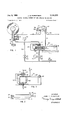
FIG. 1 is a schematic view showing a first embodiment of the control system in operative relation to a web-unreeling device;
FIG. 2 i a view in elevation showing a tension-transmitting roll of FIG. 1;
FIG. 3 is a schematic view showing a modified valve arrangement;
FIG. 4 is a schematic view showing a second embodiment of the control system; and
FIG. 5 is a partial schematic view showing a modifica tion of the control system.
Referring to FIGS. 1 and 2, a first form of the improved control system is shown operatively connected with an illustrative web-feeding device, comprising a webunreeling stand, which includes a supply reel 10 carrying a roll of web of strand material 12 thereon, and journalled in suitable bearings (not shown) for feeding the web to a processing device or to a take-up reel; positive drive means withdraw the web from the reel 10 in the direction shown by the arrows. The tension control system includes pressure-regulated means for maintaining a uniform Web tension as the web is unreeled. While variious tension control devices may be utilized within the scope of the invention, an illustrative brake 14 is shown, which comprises a split-ring engaging the periphery of the reel 10 and having one arm 17 mounted in a stationary support 16. A free arm 18 is drivingly connected with the piston 19 of a fluid motor 20, which is connected with a branched fluid conduit 22, for exerting variable braking torque on the supply reel.-
, thereto.
To sense the tension of the web, a tension-transmitting roll 24 is wrapped by the web intermediate a pair of idler rolls 26, whose function is to provide adaquate wrap about the roll 24 to transmit a component of web tension The tension-transmitting roll is pivotally and rotatably mounted by means of a ball bushing 28 supporting one end of its axle 30 in a standard 32. The opposite end of the axle is pivotally and rotatably supported in a lever arm 34, which is pivotally mounted by a stub shaft 36 in a stationary support 38.
A force proportionate to the web tension is applied by the arm 34 through a rod 41 to a force-balancing valve unit generally designated at 40. The valve unit is organized on a base 42 which rests upon a stationary support 44, and includes a valve member or load-bearing plate 46, pivotally supported at 48 on the base. The base 42 includes an overhanging flange portion 49, in which a branch of the conduit 22 terminates. The valve member 46 bears an O-ring 50, which cooperates with the flange 49 to form a variable pressure-release orifice 51. Air or other fluid under pressure is supplied to the branched conduit 22 from any suitable source, and adjustable orifice means are interposed in the conduit, comprising an adjustable needle valve 56 in the preferred embodiment shown. It will be understood, however, that a fixed orifice may be used instead of an adjustable orifice. A
v rod 41 times its moment arm about pivot 48.
pressure-indicating gage 58 is placed in the branched conduit to indicate the pressure therein.
The tension force supplied to the valve member 46 by the rod'dl is balanced by means of a pressure support cylinder 69, having an annular recess 62 in which an O- 'ring 64, which may preferably be resilient, is slidably and sealingly received, resting upon the base 42. Pressure suflicient to balance the applied tension force is supplied interiorly of the air cylinder by a conduit 66 communicating with the air supply, and having an adjustable pressure regulating valve 68 furnished with an indicating gage 70. It will be understood that the air supply pres sure and the effective area of the support cylinder 6% should be selected with consideration given to the anticipated range of web tension, 50 that the pressure supplied to the support cylinder may be regulated to balance the valve member in an open condition of the orifice S1. The moment arm of application of the tension force may also be varied by moving the rod 41 along the valve member 46.
It will be evident that the pressure in conduit 22 multiplied by the area within the circle of O-ring 50 times its moment arm about pivot 48 will be equal to the upward force produced by pressure in conduit 65 times its moment arm about pivot 48 minus the downward force in In other words, the pressure in conduit 22 (and consequently brake torque) will be proportionate to the diilerence between tension desired and tension actually existing in the web.
This makes it apparent that tension existing cannot exactly equal tension desired, but the residual error may be made as small as desired by making C ring $6 small. On the other hand, the fact that there is a residual error due to the feedback of brake pressure into the control results in a control which can be both relatively rapid acting and smooth and stable in operation. Such a control, as is Well known to those versed in the art, is generically referred to as droop stabilized."
In use, valve 68 is adjusted until the pressure indicated by gage 70 corresponds to the tension desired. This pressure may be considered to consist of two components: the tare pressure required to balance the weight of the mechanical parts and the pressure in excess of this tare pressure which is proportionate to tension desired. This pressure forces valve member 46 upward, tending to close orifice 51. This raises the pressure in conduit 22, which increases brake torque and consequently also increases web tension and thus the downward force in rod 4-1, until balance is restored in valve member 46.
Referring to FIG. 3, a modified form of force-balancing valve is illustrated, parts similar to those of the preceding embodiment being similarly numbered, with prime superscripts. The pressure support cylinder 6% in this case comprises a bellows, while the orifice 51' is formed between a conical seat 72' formed in the flange 49' and a conical valve body 74 mounted on the valve member 46'. The function of this apparatus is substantially the same as that of the preceding embodiment, and it will be understood that other forms of this apparatus may be utilized, such as are adapted to apply a regulated pressure against the valve member to balance the tension load in such manner as to modulate the air pressure in the conduit 22 as a continuous function of the difference between the desired tension and the tension existing in the web.
A modified embodiment of the improved control system is shown in FIG. 4, in which several additional features are provided. Elements similar to those of the embodiment of FIG. 1 are similarly numbered. An adjustable pressure regulating valve 86, furnished with an indicating gauge 82, is interposed in the air supply line in advance of the adjustable needle valve 56, for reducing the pressure level during start-up of the apparatus. At the commencement of a reeling operation, it may be desirable to reduce the pressure supplied to the valve 56, since the initial tension load applied by the rod 41 will consist solely of the weight of the roll 24 if there is substantially no tension applied to the web 12 at this time; consequently, the orifice 51 of the valve unit 40 may initially be completely closed. With a normal air supply, a very high pressure may therefore be applied to the brake cylinder 2% creating an excessive initial tension as the reeling operation begins. This can be avoided by adjusting the regulator 8b to sharply reduce the pressure of the air supply at this time, thereby limiting the tension applied by the brake to a safe value, even though the orifice ill may be fully closed. The regulator 88 should be adjusted to pass a normal supply pressure as soon as the web has commenced to travel and any slack has been taken up so that increases in brake pressure may be sensed in terms of the resulting increase of tension as measured by the force applied to rod 41. It should be noted that the regulator 89 must be placed in advance of the needle valve 56, as the latter serves to restrict the rate of flow of air to the valve unit so for the control of pressure in the conduit 22 by the position of the valve unit; it the pressure in the conduit downstream of the needle valve were regulated at a fixed value, it would of course defeat the proper functioning of the system.
An additional feature in the embodiment of FIG. 4 comprises means for preventing continuous variation of the brake pressure by minor fluctuation of the control pressure in the conduit 22. As a practical matter, the tension usually need not be controlled at a single precise value; it is suificient to hold it within reasonable tolerance limits of a desired mean value. Consequently, the control system is prevented from altering the brake pressure so long as the tension remains intermediate these tolerance limits and produces correspondingly small variations in the control pressure. The resulting reduction in the frequency of variation of the brake pressure affords increased life to the brake actuating elements. The means preferably employed for this purpose are a pair of spring loaded ball-check valves 83 and 84 arranged in parallel branches of the conduit 22. The spring constant and free length of the spring 86 in valve 84 are selected to exert a negligibly small compression load. It will be apparent that either valve opens only when a suificient diiierential pressure of appropriate sense exists between the conduit 22 and the brake cylinder 29, to overcome the compression load of its spring, and that the valve 84- will open under a smaller differential pressure than the valve 83. The valve 83 is provided with an adjustment screw 92 for setting the compression load of its spring 90, so that a desired difierence in the operating pressure levels of the two valves may be selected.
In operation, a variation in either sense from the predetermined mean of the control pressure in the conduit 22 which is not sufiiciently large to create the operative pressure differential in either valve, will not affect the applied brake pressure. If, however, the tension in the web should increase sufiiciently to reduce the pressure in conduit 22 so far that an upper tolerance limit of tension is passed, the valve 83 will open to relieve the brake pressure, and thereby restore the tension to a value within the upper tolerance limit, thus re-closing the valve and inactivating the control. On the other hand, should the level of tension in the web decrease below a lower tolerance limit, the pressure in conduit 22. will increase correspondingly; and the differential pressure will open the valve 84 to increase the brake pressure, and thereby bring about an increase in tension to a value within the lower tolerance limit. The tension prevailing in the Web is thereby permitted to vary Within a dead zone defined between the upper and lower tolerance limits, without bringing about any change in the brake pressure. The difference between the tension levels of the two tolerance limits, i.e., the range of tolerated deviation, may be adjusted by altering the compression of the spring 90 by means of the screw 92.
In the forms shown the air pressure prevailing in the branched conduit 22 is proportionate to the difference between the desired tension level and the tension existing in the web; but it will be understood that the tension force may be applied in a sense to close rather than to open the orifice, provided that the pressure signal is inverted for controlling the tension control means.
A further refinement is shown in partial schematic drawing, FIG. 5. Here a simple throttling valve 94 restricts the flow of pressurized fluid to and from cylinder 20. This valve acts as a filter or sensitivity control so that the brake may be made to respond more slowly to control signals, avoiding unnecessary brake action in response to rapid small variations in tension. This feature may be used instead of or in series with the check valve configuration of FIG. 4.
The improved tension control system has been illustrated in conjunction with a web-unwinding stand, in which tension is controlled by a brake. However, it will be understood that this tension control is equally useful for regulating a drive motor or a slip clutch used for drawing the web forwardly through any processing device, or onto a take-up reel. In a re-reeling operation, for example, a second tension control system may control an air slip clutch driving a take-up reel, provided that positive drive means such as constant-speed nip rolls engage the web between the two control points. The system is equally useful for controlling the tension of a web passing from one processing device to another, as, for example, from a mangle to a dryer or from a coater to a calendar, and in laminating, printing, and trimming processes.
While I have illustrated and described preferred embodiments of the invention by way of illustration, it will be understood by those skilled in the art that various additional changes and modifications may be made without departing from the true spirit and scope of the invention, which I therefore intend to define in the appended claims without limitation to the details of the foregoing embodiments.
What I claim is:
1. A tension control system for use with web-feeding mechanisms, comprising: a force-balancing valve unit, including a valve member movably mounted thereon, a fixed orifice formed in said valve unit and valved by said member to form a fluid-release orifice therebetween, and means forming a pressure support cylinder for biasing said member; means for applying a force, proportional to the tension in a web fed by said mechanism, to said valve member in a direction opposite to the bias of said pressure support cylinder; fluid supply means; first conduit means including pressure-regulating means for delivering fluid from said fluid supply means to said support cylinder under a predetermined regulated pressure to balance said tension force for varying the area of said fluid-release orifice as a continuous function of the relationship between the regulated pressure and the applied tension force; second conduit means connected with said fluidrelease orifice; orifice means connected for delivering fluid from said supply means at a limited rate of flow to said second conduit means for control of the pressure therein by the opening of said fluid-release orifice; and web tension control means connected for control by the pressure in said second conduit means to maintain the web tension substantially at a predetermined mean value dependent upon the level of the regulated pressure delivered to said support cylinder.
2. A tension control system as recited in claim 1 in which adjustable valve means is incorporated in the connection between the web tension control means and the second conduit means.
3. A continuous tension control system for use with web-feeding mechanisms, comprising: a force-balancing valve unit, including a valve member movably mounted thereon, a fixed orifice formed in said valve unit and valved by said member to form a fluid-release orifice therebetween, and means forming a pressure support cylinder for biasing said member in a direction to close said orifice; a roll for engaging a web fed by said mechanism, said roll being supported by said valve member for applying a force, proportional to the tension in the web, to said valve member in a direction to open said orifice; fluid supply means; first conduit means including pressureregul ating means for delivering fluid from said fluid supply means to said support cylinder under a predetermined regulated pressure to balance said tension force for varying the area of said fluid-release orifice as a continuous function of the relationship between the regulated pressure and the applied tension force; second conduit means connected with said fluid-release orifice; orifice means connected for delivering fluid from said supply means at a limited rate of flow to said second conduit means for control of the pressure therein by the opening of said fluid-release orifice; and web tension control means connected for control by the pressure in said second conduit means to maintain the web tension substantially at a predetermined mean value dependent upon the regulated pressure delivered to said support cylinder.
4. A continuous tension control system for use with a web-feeding mechanism including a supply reel having a length of web material wound thereon, said system comprising: a force-balancing valve unit, including a valve member movably mounted thereon, a fixed orifice formed in said valve unit and valved by said member to form a fluid-release orifice therebetween, and means forming a pressure support cylinder for biasing said member in a direction to close said orifice; means for applying a force, proportional to the tension in a web fed by said mechanism, to said valve member in a direction tending to open said orifice; fluid supply means; first conduit means including adjustable pressure-regulating means for delivering fluid from said fluid supply means to said support cylinder under an adjustable regulated pressure to balance said tension force for varying the area of said fluid-release orifice to a variable extent as a continuous function of the relationship between the regulated pressure and the applied tension force; second conduit means connected with said fluid-release orifice; orifice means connected for delivering fluid from said supply means at a limited rate of flow to said second conduit means for control of the pressure therein by the opening of said fluid-release orifice; and pressure-actuated brake means for said supply reel operatively connected with said second conduit means to adjust the braking torque applied to said supply reel as a function of the pressure in said second conduit means, whereby the web tension is maintained substantially at a mean value deter-mined by the adjustment of said pressure-regulating means.
5. A tension control system for use with web-feeding mechanisms, comprising: a force-balancing valve unit, including a valve member movably mounted thereon, a fixed orifice formed in said valve unit and valved by said member to form a fluid-release orifice therebetween, and means forming a pressure support cylinder for biasing said member in a direction to close said orifice; means for applying a force, proportional to the tension in a web fed by said mechanism, to said valve member in a direction to open said orifice; fluid supply means; first conduit means including pressure-regulating means for delivering fluid from said fluid supply means to said support cylinder under a predetermined regulated pressure to balance said tension force for varying the area of said fluid-release orifice as a continuous function of the relationship between the regulated pressure and the applied tension force; second conduit means connected with said fluid-release orifice; orifice means connected for delivering fluid from said supply means at a limited rate of flow to said second conduit means for control of the pressure therein by the opening of said fluid-release orifice; means selectively operable to reduce the pressure of fluid delivered by said supply means to said orifice means for preventing an excessive increase of the pressure in said second conduit means arising from insufficient tension in said web to maintain said fiu-id release orifice open; and Web tension control means connected for control by the pressure in said second conduit means to maintain the Web tension substantially at a predetermined mean value dependent upon the regulated pressure delivered to said support cylinder.
6 A continuous tension control system for use with web-feedingmechanisms, comprising: a fcrce-balancing valve unit, including a valve member movably mounted thereon, a fixed orifice formed in said valve unit andvalvedby said member to form a fluid-release orifice therebetween, and means forming a pressure support cylinder for biasing said member .in a direction to close said orifice; means. for applying a force, proportional to the tension in a Web fed by said mechanism, to said valve member in a direction to open said orifice; fluid supply means; first conduit means including pressure-regulating means. for delivering fluid from said fluid supply means to said support cylinder under a predetermined regulated pressure to balance saidtension force for varying the area of said fluid-release orifice as a continuous function of the relationship between the regulated pressure and the applied tension force; second conduit means connected with said fluid-release orifice; orifice means connected for delivering fluid from said supply means at a limited rate of flow to said second conduit means for control of the pressure therein by the opening of said fluid-release orifice; pressure-responsive web tension control means; and biased normally-closed valve means constructed and arranged to communicate said web tension control means with said second conduit means only upon the occurrence of difierentials of either sense between the pressures therein in excess of predetermined values; whereby the tension in said Web is maintained substantially at a predetermined mean value dependent upon the regulated pressure delivered to said support cylinder, and is variable within tolerance limits of deviation dependent upon the values of said pressure differentials.
7. A tension control system as recited in claim 6, in which said biased normally-closed valve means comprise a pair of one-Way check valves arranged in parallel fio-W relation for opposed directions of flow, said check valves having biases for opening at values of differential pressure corresponding to upper and lower tolerance limits of deviation of the Web tension from the mean value.
8. A tension control system as recited in claim 7, in which at least one of said check valves includes means for adjusting the bias thereof to vary the range of tension levels included between the upper and lower tolerance limits.
References Cited by the Examiner UNITED STATES PATENTS 2,343,181 2/44 Heinz 242-7543 2,667,311 1/54 Packer et a1. 242-7543 2,924,869 2/60 Klein et a1 242-75.43 2,974,893 3/61 Aaron 24275.43 2,983,463 5/61 Aaron et al 242-7543 2,988,297 6/61 PaWlowski 24275,43 3,083,602 4/63 Obensh-ain 242-7543 X MERViN STEIN, Primary Examiner.
Claims (1)
1. A TENSION CONTROL SYSTEM FOR USE WITH WEB-FEEDING MECHANISMS, COMPRISING: A FORCE-BALANCING VALVE UNIT, INCLUDING A VALVE MEMBER MOVABLY MOUNTED THEREON, A FIXED ORIFICE FORMED IN SAID VALVE UNIT AND VALVED BY SAID MEMBER TO FORM A FLUID-RELEASE ORIFICE THEREBETWEEN, AND MEANS FORMING A PRESSURE SUPPORT CYLINDER FOR BIASING SAID MEMBER; MEANS FOR APPLYING A FORCE, PROPORTIONAL TO THE TENSION IN A WEB FED BY SAID MECHANISM, TO SAID VALVE MEMBER IN A DIRECTION OPPOSITE TO THE BIAS OF SAID PRESSURE SUPPORT CYLINDER; FLUID SUPPLY MEANS; FIRST CONDUIT MEANS INCLUDING PRESSURE-REGULATING MEANS FOR DELIVERING FLUID FROM SAID FLUID SUPPLY MEANS TO SAID SUPPORT CYLINDER UNDER A PREDETERMINED REGULATED PRESSURE TO BALANCE SAID TENSION FORCE FOR VARYING THE AREA OF SAID FLUID-RELEASE ORIFICE AS A CONTINUOUS FUNCTION OF THE RELATIONSHIP BETWEEN THE REGULATED PRESSURE AND THE APPLIED TENSION FORCE; SECOND CONDUIT MEANS CONNECTED WITH SAID FLUIDRELEASE ORIFICE; ORIFICE MEANS CONNECTED FOR DELIVERING FLUID FROM SAID SUPPLY MEANS AT A LIMITED RATE OF FLOW TO SAID SECOND CONDUIT MEANS FOR CONTROL OF THE PRESSURE THEREIN BY THE OPENING OF SAID FLUID-RELEASE ORIFICE; AND WEB TENSION CONTROL MEANS CONNECTED FOR CONTROL BY THE PRESSURE IN SAID SECOND CONDUIT MEANS TO MAINTAIN THE WEB TENSION SUBSTANTIALLY AT A PREDETERMINED MEAN VALUE DEPENDENT UPON THE LEVEL OF THE REGULATED PRESSURE DELIVERED TO SAID SUPPORT CYLINDER.
Priority Applications (1)
| Application Number | Priority Date | Filing Date | Title |
|---|---|---|---|
| US353317A US3164333A (en) | 1964-03-17 | 1964-03-17 | Tension control system for web-feeding mechanisms |
Applications Claiming Priority (1)
| Application Number | Priority Date | Filing Date | Title |
|---|---|---|---|
| US353317A US3164333A (en) | 1964-03-17 | 1964-03-17 | Tension control system for web-feeding mechanisms |
Publications (1)
| Publication Number | Publication Date |
|---|---|
| US3164333A true US3164333A (en) | 1965-01-05 |
Family
ID=23388615
Family Applications (1)
| Application Number | Title | Priority Date | Filing Date |
|---|---|---|---|
| US353317A Expired - Lifetime US3164333A (en) | 1964-03-17 | 1964-03-17 | Tension control system for web-feeding mechanisms |
Country Status (1)
| Country | Link |
|---|---|
| US (1) | US3164333A (en) |
Cited By (12)
| Publication number | Priority date | Publication date | Assignee | Title |
|---|---|---|---|---|
| US3317977A (en) * | 1964-07-31 | 1967-05-09 | Techniservice Corp | Method and apparatus for unwinding and treating strand from a traversewound package |
| US3330457A (en) * | 1965-02-11 | 1967-07-11 | Mount Hope Machinery Ltd | Total tension monitor and control system |
| US3362218A (en) * | 1964-04-17 | 1968-01-09 | Alfa Laval Ab | Force measuring means |
| US3525480A (en) * | 1967-05-29 | 1970-08-25 | Dennis Willard | Magnetic tape transport |
| US3777959A (en) * | 1972-02-25 | 1973-12-11 | Du Pont | Apparatus for monitoring and controlling tension in an advancing flexible elongate material |
| US3782653A (en) * | 1971-03-20 | 1974-01-01 | Masson Scott Thrissell Eng Ltd | Web tension control apparatus |
| US3785581A (en) * | 1969-02-28 | 1974-01-15 | Elitex Z Textil Strojirenstvi | Winding stop motion for textile winding machines |
| US3826438A (en) * | 1964-07-31 | 1974-07-30 | Textured Yarn Co | Strand treatment |
| US4316587A (en) * | 1979-06-08 | 1982-02-23 | Astin-France Assistance Technique Industrille | Device for regulating the tension of a travelling web |
| US4422592A (en) * | 1982-01-11 | 1983-12-27 | Rennco Incorporated | Brake mechanism for spool |
| US6820833B1 (en) * | 1999-09-03 | 2004-11-23 | Ingenjoersfirman Elektroteknik Ietv Ab | Method for controlling a yarn processing system and a yarn processing system |
| US20090108044A1 (en) * | 2005-12-20 | 2009-04-30 | Gerhard Middelberg | Web-Guiding or Sheet-Guiding Machine, and Method of Operating the Same |
Citations (7)
| Publication number | Priority date | Publication date | Assignee | Title |
|---|---|---|---|---|
| US2343181A (en) * | 1940-04-03 | 1944-02-29 | Winfield B Heinz | Automatic tension control |
| US2667311A (en) * | 1950-10-27 | 1954-01-26 | British Insulated Callenders | Means for controlling the tension in running strip |
| US2924869A (en) * | 1954-03-01 | 1960-02-16 | Deering Milliken Res Corp | Brake and braking system |
| US2974893A (en) * | 1956-11-19 | 1961-03-14 | Cameron Machine Co | Apparatus for controlling tension in a running web |
| US2983463A (en) * | 1957-03-21 | 1961-05-09 | Cameron Machine Co | Apparatus for controlling the tension in a running web |
| US2988297A (en) * | 1956-05-02 | 1961-06-13 | Walter F Pawlowski | Automatic control mechanism for reeling and unreeling |
| US3083602A (en) * | 1961-01-13 | 1963-04-02 | West Virginia Pulp & Paper Co | Precise web metering device |
-
1964
- 1964-03-17 US US353317A patent/US3164333A/en not_active Expired - Lifetime
Patent Citations (7)
| Publication number | Priority date | Publication date | Assignee | Title |
|---|---|---|---|---|
| US2343181A (en) * | 1940-04-03 | 1944-02-29 | Winfield B Heinz | Automatic tension control |
| US2667311A (en) * | 1950-10-27 | 1954-01-26 | British Insulated Callenders | Means for controlling the tension in running strip |
| US2924869A (en) * | 1954-03-01 | 1960-02-16 | Deering Milliken Res Corp | Brake and braking system |
| US2988297A (en) * | 1956-05-02 | 1961-06-13 | Walter F Pawlowski | Automatic control mechanism for reeling and unreeling |
| US2974893A (en) * | 1956-11-19 | 1961-03-14 | Cameron Machine Co | Apparatus for controlling tension in a running web |
| US2983463A (en) * | 1957-03-21 | 1961-05-09 | Cameron Machine Co | Apparatus for controlling the tension in a running web |
| US3083602A (en) * | 1961-01-13 | 1963-04-02 | West Virginia Pulp & Paper Co | Precise web metering device |
Cited By (13)
| Publication number | Priority date | Publication date | Assignee | Title |
|---|---|---|---|---|
| US3362218A (en) * | 1964-04-17 | 1968-01-09 | Alfa Laval Ab | Force measuring means |
| US3317977A (en) * | 1964-07-31 | 1967-05-09 | Techniservice Corp | Method and apparatus for unwinding and treating strand from a traversewound package |
| US3826438A (en) * | 1964-07-31 | 1974-07-30 | Textured Yarn Co | Strand treatment |
| US3330457A (en) * | 1965-02-11 | 1967-07-11 | Mount Hope Machinery Ltd | Total tension monitor and control system |
| US3525480A (en) * | 1967-05-29 | 1970-08-25 | Dennis Willard | Magnetic tape transport |
| US3785581A (en) * | 1969-02-28 | 1974-01-15 | Elitex Z Textil Strojirenstvi | Winding stop motion for textile winding machines |
| US3782653A (en) * | 1971-03-20 | 1974-01-01 | Masson Scott Thrissell Eng Ltd | Web tension control apparatus |
| US3777959A (en) * | 1972-02-25 | 1973-12-11 | Du Pont | Apparatus for monitoring and controlling tension in an advancing flexible elongate material |
| US4316587A (en) * | 1979-06-08 | 1982-02-23 | Astin-France Assistance Technique Industrille | Device for regulating the tension of a travelling web |
| US4422592A (en) * | 1982-01-11 | 1983-12-27 | Rennco Incorporated | Brake mechanism for spool |
| US6820833B1 (en) * | 1999-09-03 | 2004-11-23 | Ingenjoersfirman Elektroteknik Ietv Ab | Method for controlling a yarn processing system and a yarn processing system |
| US20090108044A1 (en) * | 2005-12-20 | 2009-04-30 | Gerhard Middelberg | Web-Guiding or Sheet-Guiding Machine, and Method of Operating the Same |
| US9617107B2 (en) | 2005-12-20 | 2017-04-11 | Windmoeller & Hoelscher Kg | Web-guiding or sheet-guiding machine, and method of operating the same |
Similar Documents
| Publication | Publication Date | Title |
|---|---|---|
| US3164333A (en) | Tension control system for web-feeding mechanisms | |
| US2343181A (en) | Automatic tension control | |
| US3202376A (en) | Rollstand drive | |
| US3724733A (en) | Web infeed mechanism | |
| US3784123A (en) | Tension control system | |
| US3322315A (en) | Apparatus for controlling the tension in a web | |
| US3083602A (en) | Precise web metering device | |
| US2710153A (en) | Web tension control system | |
| US3239161A (en) | Rollstand drive | |
| GB1573383A (en) | Apparatus for applying pressure to a web | |
| US3910522A (en) | Web tension control system | |
| US2988297A (en) | Automatic control mechanism for reeling and unreeling | |
| US2755032A (en) | Tension regulator and guide and control means therefor | |
| US2983463A (en) | Apparatus for controlling the tension in a running web | |
| US3974948A (en) | Web tension control device | |
| US2462558A (en) | Tension control means for running webs | |
| US3306547A (en) | Winding apparatus | |
| US3330457A (en) | Total tension monitor and control system | |
| US2965326A (en) | Apparatus for controlling tension in a web | |
| US3289967A (en) | Tension regulator | |
| US3240058A (en) | Continuous tension monitor for webfeeding mechanisms | |
| US2922594A (en) | Control apparatus for air-operated devices | |
| US4245793A (en) | Draw off control system for a roll of material | |
| US2726858A (en) | Web position control mechanism | |
| US3465981A (en) | Disc brakes and torque varying means therefor |