US3085536A - Multiple hull boat - Google Patents
Multiple hull boat Download PDFInfo
- Publication number
- US3085536A US3085536A US4774A US477460A US3085536A US 3085536 A US3085536 A US 3085536A US 4774 A US4774 A US 4774A US 477460 A US477460 A US 477460A US 3085536 A US3085536 A US 3085536A
- Authority
- US
- United States
- Prior art keywords
- hull
- boat
- elements
- water
- planing
- Prior art date
- Legal status (The legal status is an assumption and is not a legal conclusion. Google has not performed a legal analysis and makes no representation as to the accuracy of the status listed.)
- Expired - Lifetime
Links
Images


Classifications
-
- B—PERFORMING OPERATIONS; TRANSPORTING
- B63—SHIPS OR OTHER WATERBORNE VESSELS; RELATED EQUIPMENT
- B63B—SHIPS OR OTHER WATERBORNE VESSELS; EQUIPMENT FOR SHIPPING
- B63B1/00—Hydrodynamic or hydrostatic features of hulls or of hydrofoils
- B63B1/02—Hydrodynamic or hydrostatic features of hulls or of hydrofoils deriving lift mainly from water displacement
- B63B1/10—Hydrodynamic or hydrostatic features of hulls or of hydrofoils deriving lift mainly from water displacement with multiple hulls
- B63B1/12—Hydrodynamic or hydrostatic features of hulls or of hydrofoils deriving lift mainly from water displacement with multiple hulls the hulls being interconnected rigidly
- B63B1/125—Hydrodynamic or hydrostatic features of hulls or of hydrofoils deriving lift mainly from water displacement with multiple hulls the hulls being interconnected rigidly comprising more than two hulls
- B63B2001/126—Hydrodynamic or hydrostatic features of hulls or of hydrofoils deriving lift mainly from water displacement with multiple hulls the hulls being interconnected rigidly comprising more than two hulls comprising more than three hulls
Definitions
- This invention relates to boats and more particularly to an improved multiple hull boat.
- a displacement hull type boat maintains substantially the same displacement or submerged hull volume whether at rest or traveling at maximum speed and thus the submerged portion of the hull at all times travels through the water.
- Hulls of this type reach a certain predetermined speed with the application of a compartively small amount of power, but require progressively larger amounts of power for progressively smaller increases in speed above the predetermined speed.
- This constant displace ment characteristic also results in a large load carrying capacity, economy of operation and stability or lesser sensitivity to changes in weight distribution.
- Examples of boats utilizing a pure displacement type hull are the large ocean liners, naval boats, most commercial and fishing boats, barges, houseboats, and sail-boats.
- planing hull type boat is capable of a speed many times greater than that of a displacement hull boat of the same size, the power required is also many times greater and economy of operation and stability are also sacrificed.
- Boats utilizing what may be termed a true planing hull are usually of the racing type such as hydroplanes and the like.
- a semi-displacement hull is a planing hull and thus has a variable displacement depending upon the speed of the boat.
- a hull design permits substantially all of the boat to ride up on top of the water when traveling at planing speeds and above with only a small portion of the boat traveling through the water in the manner of a displacement hull.
- the semi displacement hull thus has the high speed characteristics of a planing hull, but with somewhat greater load carrying capacity and stability, and slightly less sensitivity to weight distribution.
- the factor of weight distribution is probably the most important as concerns operating efiiciency and maximum speed. This factor has the least effect on displacement type hulls, because of the widely distributed flotation force acting along the entire length of the hull, but is quite significant in planing and semi-displacement type hulls where the flotation force is concentrated at a small area of the hull when the boat is planing. Thus, improper weight distribution may prevent a boat utilizing either of the latter type hulls from rising on top of the water, particularly where the boat is only marginally powered or is underpowered.
- the present invention provides an effective solution to this problem in the form of a novel multiple hull boat which utilizes a plurality of hull elements of the type having a generally V-shaped bow and which are adapted to plane, the hull elements being rigidly secured to a common platform or frame at their optimum planing angle such that the assembly is capable of traveling at high speeds in the manner of a runabout or cruiser and with the lateral stability of a displacement hull type boat.
- the multiple hull boat of the present invention is capable of accommodating large variations in weight distribution without significant loss in maximum speed.
- Another object of the invention is to provide an improved multiple hull boat which combines the advantages of a displacement and planing type hull and which is not sensitive to variations in load distribution.
- a further object of the invention is to provide an improved multiple hull boat construction of the houseboat type, which is capable of planing and thus attaining high cruising and maximum speeds.
- Another object of the invention is to provide an 1mproved multiple hull boat construction which utih zes a plurality of semi-displacement type hull elements rigldly secured in fixed relation to each other and the surface of the water at an angle corresponding to the optimum planing angle of each hull element so that the assembly is capable of reaching high speeds.
- Still another object of the invention is to provide an improved houseboat utilizing two pairs of planing type hull elements arranged in longitudinally and laterally spaced relation and rigidly secured to a common platform or frame at their optimum angle of inclination relative to the surface of the water for maximum speed so as to permit the houseboat to plane and travel at a speed comparable to an equivalent cabin cruiser.
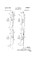
- FIG. 1 is a diagrammatic side elevational view of a typical semi-displacement type hull boat showing the relative position thereof in relation to the surface of the water when the boat is at rest;
- FIG. 2 is a view similar to FIG. 1 and showing the relative position of the boat in relation to the surface of the water when the boat is underway;
- FIG. 3 is a view similar to FIG. 2 but showing the relative position of the boat in relation to the surface of the water when the load is distributed most efiiciently for maximum speed operation;
- FIG. 4 is a view similar to FIG. 1 showing the approximate position that the boat would assume in relation to the surface of the water when the boat is at rest and when loaded so as to achieve the maximum speed position illustrated in FIG. 3;
- FIG. 5 is a diagrammatic side elevational view of a pair of semi-displacement hull type boats secured together in tandem and each rigidly held at a predetermined angle in relation to the surface of the water, the arrangement comprising one embodiment of the invention
- FIG. 6 is a view of the assembly of FIG. 5 when the latter is underway and showing the position of the following hull in relation to the wake of the preceding hull;
- FIG. 7 is a side elevational view of a houseboat constructed according to the principles of the present inven tion, the latter comprising a second embodiment thereof;
- FIG. 8 is an oblique front perspective view of the houseboat of FIG. 7;
- FIG. 9 is a perspective view of the bottom of the houseboat of FIGS. 7 and 8 and looking forwardly from the stern to show the arrangement of the power plants thereof.
- the present invention contemplates a multiple hull boat construction which utilizes a plurality of hull elements of the type adapted to plane, e.g., a semidisplacement or planing type hull, rigidly secured to a common platform or frame to provide a unitary assembly.
- Each hull element is disposed at a predetermined angle with reference to the surface of the water when the assembly is at rest corresponding to its optimum planing angle to attain maximum speed.
- the hull elements are of sufficient displacement so that the common platform or connecting frame does not normally contact the water. Because of the novel arrangement of the hull elements, the resulting assembly is capable of high s eeds but with far less sensitivity to changing weight distribution in comparison with an equivalent single hull boat.
- the preferred embodiment of the invention is also very stable to lateral forces.
- FIGS. 1-4 a typical semi-displacement hull boat is illustrated and designated generally at 10, the latter being exemplary of the type of hull elements employed in each of the embodiments of the invention.
- the surface of the water is indicated by the line W and the respective centers of gravity and buoyancy of the boat 10 are indicated at C.G. and GB.
- the center of gravity is of course the point about which the boat, its equipment, and passengers are in balance, and the center of buoyancy is the point at which the resultant flotation force caused by the displacement of the water that would otherwise occupy the volume of the submerged portion of the hull is assumed to act.
- the latter point will of course vary to much greater extent than the center of gravity, particularly in small boats.
- FIG. 1 thus shows the position that the boat 10 would assume at rest in relation to the surface of the water W with a load distribution to maintain the boat substantially level.
- the boat 10 has its how 11, which is preferably V-shaped, somewhat more elevated than its stern 12 in relation to the surface of the water W.
- the bottom or keel, indicated at 13, of the boat 10 is in this instance generally parallel to the surface of the water W.
- the top or gunwale of the boat 10 is indicated at 14, and the center of buoyancy of the submerged portion of the hull, indicated at 15, is approximately in vertical alignment with its center of gravity. Quantitatively, the volume of water displaced by the portion 15 is equal to the weight of the boat passengers, and equipment.
- FIG. 2 represents the position assumed by the boat 10 when the latter is underway.
- the how 11 has thus become elevated and the stern 12 depressed in relation to FIG. 1 so that the boat 10 is inclined to the surface of the water W at a steep angle which may range up to 20 or more.
- the center of buoyancy has thus shifted to ward the stern but because of the interaction of the hull, water, and engine thrust forces, the boat cannot return to a level condition.
- a boat traveling in this position is operating inefficiently and cannot attain its designed maximum speed.
- the position of the boat 10 illustrated in FIG. 2 also represents a common condition usually experienced in underpowered semi-displacement type small boats which is both ineflicient and dangerous.
- FIG. 3 represents the ideal or optimum position of the boat 10 in relation to the surface of the water W for maximum speed and efiiciency. It will be noted that the hull, and in the case of the boat 10, its bottom or keel 13, is inclined to the surface of the water by only a small angle, in this instance about 1. This angle is indicated in FIG. 3 in relation to the bottom or keel 13. The submerged portion 15 of the hull is much less than that in FIGS. 1 and 2, and the center of buoyancy of the hull has also shifted toward the how 11.
- the 1 angle of inclination of the boat 10 has been indicated in relation to its bottom or keel 13, this angle is more properly referenced to what may be termed the plane of the planing surface of the hull.
- Such a plane is theoretical in that it takes into account all of the contours of the submerged portion of the hull and thus may or may not be parallel to the bottom or keel of the boat, depending upon its design.
- the 1 angle is an average, based upon experiment, and will of course also vary for individual boats. As previously mentioned, this angle should not be greater than about 3 and preferably about 1 to 2. Such inclination may be achieved by the application of excess power, even with an adverse load distribution, if the hull is properly de signed.
- a tandem boat assembly 20 comprising a first embodiment of the invention.
- the boat assembly 29 preferably comprises a pair of semi-displacement type boats or hull elements 21 and 22 rigidly secured together in longitudinally spaced relation by connecting means 23, such as a pair of longitudinally extending laterally spaced elongated beams 24.
- the beams 24 are sufficiently long to overlap both hull elements 21 and 22 and thus permit a rigid securement of the beams to each boat.
- each of the hull elements 2?. and 22 is rigidly secured to the beams 24 such that the theoretical planes of their planing surfaces are inclined to the surface of the water at an angle of approximately 1 when the assembly 20 is at rest, as in FiG. 5, or underway, as in FIG. 6.
- their bottoms or keels, indicated at 25 are parallel to this plane and thus are inclined at a 1 angle.
- the transom or stern, indicated at 26, of the preceding hull 21 is spaced from the bow, indicated at 27, of the following hull 22 by a distance such that When-the assembly is traveling at planing speed, a substantial portion of the following hull 22 is ahead of the crest of the wake, indicated at W, of the preceding hull 21 (FIG. 6).
- the spacing between the hull elements 21 and 22 to achieve the condition illustrated in FIG. 6 depends upon many variables, including the respective lengths of the hulls, the horsepower of the engines employed, and the maximum speed to be achieved by the assembly. The latter factor is probably the most important, as the spacing of the crest of the wake W from the transom 26 of the preceding hull 21 is a direct function of the speed and design of the hull.
- the boat assembly 29 is preferably driven by propulsion means in the form of a pair of outboard motors (not shown) carried on the transo-ms 26 and 28 of the respec tive hull elements 21 and 22. lf a single engine is utilized, it should be mounted on the transom 28 of the following hull element 22 and should have sufiicient power to cause the assembly 20 to plane. I have found that two 35 horsepower outboard motors provide ample power to plane the assembly 20 when two heavily loaded 14-foot hull elements or boats 21 and 22 are employed to realize the advantages of the present invention.
- the assembly 2%) will travel at maximum speed for the power available and will be relatively unaffected by changes in weight distribution throughout the assembly.
- the increased length of the assembly 20 provided by the tandem arrangement of the hull elements 21 and 22 smooths the effects of wave action, and the beams 24 maybe effectively utilized for supporting superstructure in the form of a small cabin in which controls, navigational equipment, and the like may be carried.
- a houseboat 30 is illustrated, the latter being constructed according to the principles of the present invention and comprising a second and preferred embodiment thereof.
- the houseboat 30 is conventional to the extent that it includes a cabin or superstructure 31 which is mounted on a deck formed by an elongated platform or frame 32.
- the forward or bow end, indicated at 33, of the platform 32 is turned up or inclined for better resistance to wave action and to provide an air trap between the underside of the platform 32 and the surface of the water W for additional lift when the boat is traveling at high speed or against the Wind.
- the cabin 31 includes steering and engine controls 34, as well as the usual navigational equipment and living accommodations.
- the hull portion of the houseboat 30 comprises a plurality of bull elements 35, rigidly secured at their gunwales to the underside of the platform 32 in water-tight engagement.
- bull elements 35 rigidly secured at their gunwales to the underside of the platform 32 in water-tight engagement.
- four longitudinally and laterally spaced hull elements 35 are provided, each of which has the theoretical plane of its planing surface inclined at a 1 angle in relation to the surface of the water W when the houseboat 30 is at rest and uniformly loaded.
- their bottoms or keels, indicated at 40 are also parallel to this plane and thus are also inclined at 2. 1 angle to the surface of the water.
- the top rail or gunwa'le portion of each ofthe hull elements may be spaced to provide this relationship.
- the laterally spaced front and rear pairs of bull elements are arranged so that the cabin 31 is disposed substantially centrally thereabove, and have sufiicient displacement to supportthe platform or deck 32 and cabin structure 31 above the level W of the water whenthe houseboat 30 is fully loaded.
- the water and fuel tanks are desirably mounted in a zone closely adjacent the intersection of the longitudinal and transverse axes of the platform or deck 32 to minimize their effect on the trim of the boat when empty or full.
- each hull element -35 is of the semi-displacement type and is thus capable of riding on top of the water when sufficient speed is obtained.
- propulsion means in the form of four outboard motors 36 is provided. As best seen in FIGS. 7 and 9, each of the four motors 36 is mounted adjacent the stern or transom, indicated at 37, of the hull elements 35-.
- the motors 3d are preferably carried by the structure of the platform 32, though they could be mounted on the transoms 37 of the hull elements 35 or some other place.
- the forward pair of motors are disposed laterally outwardly 'of the after or rearward pair of motors, indicated at 36b, the latter being mounted on the center lines of their respective hull elements 35b.
- the lateral outward positioning of the forward pair of motors 36a also permits utilizati-on of the space therebetween.
- the transoms 37 of each hull element may be extended as a contoured flotation tank 38, the latter being recessed forwardly as at 3? to provide wells for receiving the shaft housings of the motors 36. Extension of the transoms 37 as tanks 38 also helps to prevent cavitation of the motors 36.
- Individual starting, throttle, and forward and reverse controls are provided for each of the motors 36, the rearward pair of motors 36b being movable in unison about their shaft axes by linkage 41 (FIG. 9) to provide steering control for the boat 30.
- the forward motors 36a are preferably mounted amidships or at the mid-point of the longitudinal axis of the boat 30 and are fixed against rotat-ion. Such location of the motors 36a provides superior maneuverability and control of the boat 30 during landing and when the boat is subjected to wind effects through a selective use of their forward and reverse controls.
- the boat 30 can thus be made to swing about a vertical central axis.
- the novel arrangement of the four hull elements 35 provides improved longitudinal and lateral stability to the houseboat 30, and because each of the hull elements 35 is of the semi-displacement type and is rigidly secured to the underside of the platform 32 at its optimum 1 planing angle of inclination, the houseboat 35) is capable of riding up on top of the water in the manner of a semi-displacement hull boat at speeds comparable to an equivalent cabin cruiser. Because of the aforementioned relationship of the hull elements, the boat 30 will rise substantially vertically as it 7 reaches and exceeds planing speed. Thus, the houseboat 30 eifectively combines the accommodations and comfort of a conventional houseboat with the speed and versatility of a cabin cruiser. Moreover, because of the longitudinally and laterally spaced arrangement of the hull elements 35, the houseboat 30 will resist any combination of forces tending to cause it to pitch or roll. Safety of operation is further assured by the transom extensions 38 which form flotation tanks.
- a hull assembly comprising an elongated frame-like platform, two laterally-spaced tandem pairs of semi-displacement type hull elements depending rigidly from said platform and each having a generally V-shaped bow, said hull elements being disposed at an angle of approximately 1 to 2 degrees with respect to the surface of the water, the space between the preceding and following pairs of hull elements being such that a substantial portion of the following pair rides ahead of the crest of the wake from the preceding pair when the hull assembly is moving at a planing speed, and propulsion units supported from said platform and disposed adjacent the rear end of each of said elements, the forward pair of propulsion units being spaced laterally outwardly of said rear pair and being located substantially amidsbips adjacent opposite sides of said platform to avoid wake in terference, whereby the rigid interconnection of said hull elements with said platform, their angle of disposition with respect to the surface of the water, and the longitudinal spacing thereof cooperate to permit said boat construction to obtain maximum speed when planing.
- a hull assembly comprising an elongated frame-like platform, two laterally-spaced tandem pairs of semi-displacement type hull elements depending rigidly from said platform and each having a generally V-shaped bow, said hull elements being disposed at an angle of approximately 1 to 2 degrees with respect to the surface of the water, the space between the preceding and following pairs of bull elements being such that a substantial portion of the following pair rides ahead of the crest of the Wake from the preceding pair when the hull assembly is moving at a planing speed, propulsion units supported from said platform and disposed adjacent the rear end of each said elements, the forward pair of .propulsion units being spaced laterally outwardly of said rear pair and being located substantially amidships adjacent opposite sides of said platform to avoid wake interference, and water and fuel tanks mounted substantially on the longitudinal axis of said platform between said tandem pairs of hull elements, whereby the rigid interconnection of said hull elements with said platform, their angle of disposition with respect to the surface of the water, the longitudinal spacing thereof, and the central longitudinal
Landscapes
- Physics & Mathematics (AREA)
- Fluid Mechanics (AREA)
- Chemical & Material Sciences (AREA)
- Engineering & Computer Science (AREA)
- Combustion & Propulsion (AREA)
- Mechanical Engineering (AREA)
- Ocean & Marine Engineering (AREA)
- Other Liquid Machine Or Engine Such As Wave Power Use (AREA)
Description
A ril 16, 1963 M. o. TEETOR MULTIPLE HULL BOAT 3 Sheets-Sheet 1 Filed Jan. 26, 1960 April 16, 1963 M. o. TEETOR MULTIPLE HULL BOAT 3 Sheets-Sheet 2 Filed Jan. 26, 1960 IN V EN TOR. w lf BY I April 16, 1963 M. o. TEETOR 3,085,536
MULTIPLE HULL BOAT Filed Jan. 26, 1960 3 Sheets-Sheet 3 g f. n 1
a? 77 7 A... i
United States Patent 3,085,536 MULTIPLE HULL BOAT Macy 0. Teeter, 24 Orpheum Ave, Metairie, La. Filed Jan. 26, 1960, Ser. No. 4,774
2 Claims. (Cl. 114--61) This invention relates to boats and more particularly to an improved multiple hull boat.
Marine architects and engineers, shipbuilders, and yachtsmen have long been aware of the differences between boats constructed with displacement type hulls and planing type hulls, particularly as to high speed performance, stability, and sensitivity to weight distribution. Inasmuch as each hull type has advantages over the other, many attempts have been made to provide a composite hull which exhibits the most desirable characteristics of each. Such efforts have resulted in the development of the so-called semi-displacement type hull, which, though basically a planing hull that is designed to ride on top of the water at high speed, also exhibits some of the characteristics of a pure displacement type hull, such as improved stability, better load carrying capacity, and less sensitivity to weight distribution. Comparatively recent efforts along these same lines have led to a renewal of interest in multiple hull boats, such as the catamaran, the stability characteristics of which are well known. So far as is known, however, no satisfactory hull construction has been proposed which provides the combined features of the present invention to be hereinafter described. Before proceeding with the actual description of the present invention, a brief comparison of the characteristics of the pure displacement, planing and semi-displacement type hulls may prove helpful to an understanding of the invention.
A displacement hull type boat maintains substantially the same displacement or submerged hull volume whether at rest or traveling at maximum speed and thus the submerged portion of the hull at all times travels through the water. Hulls of this type reach a certain predetermined speed with the application of a compartively small amount of power, but require progressively larger amounts of power for progressively smaller increases in speed above the predetermined speed. This constant displace ment characteristic also results in a large load carrying capacity, economy of operation and stability or lesser sensitivity to changes in weight distribution. Examples of boats utilizing a pure displacement type hull are the large ocean liners, naval boats, most commercial and fishing boats, barges, houseboats, and sail-boats.
Boats utilizing a true planing type hull may be said to have a variable displacement depending upon the speed of the boat. Thus, when at rest, a planing hull boat has a maximum displacement which becomes progressively less as the speed of the boat increases to planing speed. Above planing speed, the displacement of a planing hull type boat remains at some small substantially constant value, which is quantitatively many times less than its at rest displacement. As a consequence of this characteristic, planing hull type boats do not have their terminal speeds controlled so much by the power required to move the water during passage of the hull as they do by water frictional forces and wind resistance. Thus, while a planing hull type boat is capable of a speed many times greater than that of a displacement hull boat of the same size, the power required is also many times greater and economy of operation and stability are also sacrificed. Boats utilizing what may be termed a true planing hull are usually of the racing type such as hydroplanes and the like.
Boats utilizing a semi-displacement hull are, as the name suggests, a hybrid between a displacement and "ice planing type hull in that they exhibit some of the characteristics of each. Primarily, a semi-displacement hull is a planing hull and thus has a variable displacement depending upon the speed of the boat. Such a hull design permits substantially all of the boat to ride up on top of the water when traveling at planing speeds and above with only a small portion of the boat traveling through the water in the manner of a displacement hull. The semi displacement hull thus has the high speed characteristics of a planing hull, but with somewhat greater load carrying capacity and stability, and slightly less sensitivity to weight distribution. The majority of small and medium sized pleasure boats, and some commercial boats, utilize this type of hull.
In contrasting the characteristics of each hull design, the factor of weight distribution is probably the most important as concerns operating efiiciency and maximum speed. This factor has the least effect on displacement type hulls, because of the widely distributed flotation force acting along the entire length of the hull, but is quite significant in planing and semi-displacement type hulls where the flotation force is concentrated at a small area of the hull when the boat is planing. Thus, improper weight distribution may prevent a boat utilizing either of the latter type hulls from rising on top of the water, particularly where the boat is only marginally powered or is underpowered. Assuming sufficient power to bring the boat to planing speed, maximum speed will be obtained when the weight distribution is such that the hull is disposed at a certain angle in relation to the surface of the water. This angle, which may be termed the optimum planing angle, will of course vary within certain limits for individual boats, but is fairly constant for boats of the same size, type, and power.
Experiments have shown that a typical small to medium sized semi-displacement type hull boat, when properly loaded for maximum speed, will be disposed at an angle of not more than about 3 and preferably about 1 to 2 to the surface of the water when traveling at planing speeds and above. This same weight distribution may result in a slightly bow heavy and relatively unsafe condition when the boat is at rest or traveling at very low speeds.
With the foregoing as a background, it may be stated that up to now, no satisfactory solution has been presented to the heretofore unsolved problem of providing a boat construction which combines the advantages of displacement hull stability and lesser sensitivity to changes in weight distribution with semi-displacement or planing hull speed, and in which variations in weight distribution is not a critical factor to maximum speed performance.
The present invention provides an effective solution to this problem in the form of a novel multiple hull boat which utilizes a plurality of hull elements of the type having a generally V-shaped bow and which are adapted to plane, the hull elements being rigidly secured to a common platform or frame at their optimum planing angle such that the assembly is capable of traveling at high speeds in the manner of a runabout or cruiser and with the lateral stability of a displacement hull type boat. In addition, the multiple hull boat of the present invention is capable of accommodating large variations in weight distribution without significant loss in maximum speed.
Accordingly, it is an object of the present invention to provide an improved multiple hull boat.
Another object of the invention is to provide an improved multiple hull boat which combines the advantages of a displacement and planing type hull and which is not sensitive to variations in load distribution.
A further object of the invention is to provide an improved multiple hull boat construction of the houseboat type, which is capable of planing and thus attaining high cruising and maximum speeds.
Another object of the invention is to provide an 1mproved multiple hull boat construction which utih zes a plurality of semi-displacement type hull elements rigldly secured in fixed relation to each other and the surface of the water at an angle corresponding to the optimum planing angle of each hull element so that the assembly is capable of reaching high speeds.
Still another object of the invention is to provide an improved houseboat utilizing two pairs of planing type hull elements arranged in longitudinally and laterally spaced relation and rigidly secured to a common platform or frame at their optimum angle of inclination relative to the surface of the water for maximum speed so as to permit the houseboat to plane and travel at a speed comparable to an equivalent cabin cruiser.
Many other objects and advantages of the invention will become apparent upon making reference to the detailed description and accompanying sheets of drawings to follow in which:
FIG. 1 is a diagrammatic side elevational view of a typical semi-displacement type hull boat showing the relative position thereof in relation to the surface of the water when the boat is at rest;
FIG. 2 is a view similar to FIG. 1 and showing the relative position of the boat in relation to the surface of the water when the boat is underway;
FIG. 3 is a view similar to FIG. 2 but showing the relative position of the boat in relation to the surface of the water when the load is distributed most efiiciently for maximum speed operation;
FIG. 4 is a view similar to FIG. 1 showing the approximate position that the boat would assume in relation to the surface of the water when the boat is at rest and when loaded so as to achieve the maximum speed position illustrated in FIG. 3;
FIG. 5 is a diagrammatic side elevational view of a pair of semi-displacement hull type boats secured together in tandem and each rigidly held at a predetermined angle in relation to the surface of the water, the arrangement comprising one embodiment of the invention;
FIG. 6 is a view of the assembly of FIG. 5 when the latter is underway and showing the position of the following hull in relation to the wake of the preceding hull;
FIG. 7 is a side elevational view of a houseboat constructed according to the principles of the present inven tion, the latter comprising a second embodiment thereof;
FIG. 8 is an oblique front perspective view of the houseboat of FIG. 7; and
FIG. 9 is a perspective view of the bottom of the houseboat of FIGS. 7 and 8 and looking forwardly from the stern to show the arrangement of the power plants thereof.
Briefly described, the present invention contemplates a multiple hull boat construction which utilizes a plurality of hull elements of the type adapted to plane, e.g., a semidisplacement or planing type hull, rigidly secured to a common platform or frame to provide a unitary assembly. Each hull element is disposed at a predetermined angle with reference to the surface of the water when the assembly is at rest corresponding to its optimum planing angle to attain maximum speed. The hull elements are of sufficient displacement so that the common platform or connecting frame does not normally contact the water. Because of the novel arrangement of the hull elements, the resulting assembly is capable of high s eeds but with far less sensitivity to changing weight distribution in comparison with an equivalent single hull boat. In addition to the foregoing, the preferred embodiment of the invention is also very stable to lateral forces.
The invention will be described hereinafter in connection with two embodiments, the first utilizing two hull elements arranged in tandem, and the second and preferred embodiment utilizing two laterally spaced pairs of tandem hull elements providing four elements in all.
Before proceeding with the description of the specific embodiments of the invention, a brief explanation of the theory of the invention will be included. Thus, in FIGS. 1-4, a typical semi-displacement hull boat is illustrated and designated generally at 10, the latter being exemplary of the type of hull elements employed in each of the embodiments of the invention. In FIGS. 1-4 the surface of the water is indicated by the line W and the respective centers of gravity and buoyancy of the boat 10 are indicated at C.G. and GB. The center of gravity is of course the point about which the boat, its equipment, and passengers are in balance, and the center of buoyancy is the point at which the resultant flotation force caused by the displacement of the water that would otherwise occupy the volume of the submerged portion of the hull is assumed to act. The latter point will of course vary to much greater extent than the center of gravity, particularly in small boats.
FIG. 1 thus shows the position that the boat 10 would assume at rest in relation to the surface of the water W with a load distribution to maintain the boat substantially level. It will be observed that the boat 10 has its how 11, which is preferably V-shaped, somewhat more elevated than its stern 12 in relation to the surface of the water W. The bottom or keel, indicated at 13, of the boat 10 is in this instance generally parallel to the surface of the water W. The top or gunwale of the boat 10 is indicated at 14, and the center of buoyancy of the submerged portion of the hull, indicated at 15, is approximately in vertical alignment with its center of gravity. Quantitatively, the volume of water displaced by the portion 15 is equal to the weight of the boat passengers, and equipment.
FIG. 2 represents the position assumed by the boat 10 when the latter is underway. The how 11 has thus become elevated and the stern 12 depressed in relation to FIG. 1 so that the boat 10 is inclined to the surface of the water W at a steep angle which may range up to 20 or more. The center of buoyancy has thus shifted to ward the stern but because of the interaction of the hull, water, and engine thrust forces, the boat cannot return to a level condition. A boat traveling in this position is operating inefficiently and cannot attain its designed maximum speed. The position of the boat 10 illustrated in FIG. 2 also represents a common condition usually experienced in underpowered semi-displacement type small boats which is both ineflicient and dangerous.
FIG. 3 represents the ideal or optimum position of the boat 10 in relation to the surface of the water W for maximum speed and efiiciency. It will be noted that the hull, and in the case of the boat 10, its bottom or keel 13, is inclined to the surface of the water by only a small angle, in this instance about 1. This angle is indicated in FIG. 3 in relation to the bottom or keel 13. The submerged portion 15 of the hull is much less than that in FIGS. 1 and 2, and the center of buoyancy of the hull has also shifted toward the how 11.
While the 1 angle of inclination of the boat 10 has been indicated in relation to its bottom or keel 13, this angle is more properly referenced to what may be termed the plane of the planing surface of the hull. Such a plane is theoretical in that it takes into account all of the contours of the submerged portion of the hull and thus may or may not be parallel to the bottom or keel of the boat, depending upon its design. It should also be stated that the 1 angle is an average, based upon experiment, and will of course also vary for individual boats. As previously mentioned, this angle should not be greater than about 3 and preferably about 1 to 2. Such inclination may be achieved by the application of excess power, even with an adverse load distribution, if the hull is properly de signed. However, where the power available is barely sufficient to cause the boat to plane, it may be necessary to shift the center of gravity of the boat forwardly from its FIG. 1 position. Thus, a shift of the center of gravity of the boat It) forwardly from its position indicated at O6. to a new position C.G.' by a distance d will cause the hull to assume the desired 1 angle, as indicated in FIG. 3. The foregoing shift is usually accomplished by movement of the passengers or equipment in a small boat.
Assuming that the passengers and/ or load of the boat '10 have been moved forwardly so that the center of gravity shifts to the position CG. and the desired 1 angle of inclination is obtained at maximum speed, it will be apparent that when the boat stops or reduces speed it will then be bow heavy, as shown in FIG. 4. This condition may of course be remedied by relocation of the passengers and load as a bow heavy boat is more inefiicient and dangerous than a stern heavy boat.
From the foregoing, two principles become apparent, namely, that in most small and medium sized boats utilizing a semi-displacement type hull, maximum speed will be obtained when the hull is inclined at some predetermined angle to the surface of the water, not more than about 3 and preferably about 1 to 2, and that the fac tor of Weight distribution appears most important in obtaining maximum speed for the power available. The present invention recognizes and applies both of these principles in two specific embodiments, now to be described.
Thus, in FIGS. 5 and 6, a tandem boat assembly 20 is illustrated, the latter comprising a first embodiment of the invention. The boat assembly 29 preferably comprises a pair of semi-displacement type boats or hull elements 21 and 22 rigidly secured together in longitudinally spaced relation by connecting means 23, such as a pair of longitudinally extending laterally spaced elongated beams 24. The beams 24 are sufficiently long to overlap both hull elements 21 and 22 and thus permit a rigid securement of the beams to each boat.
According to the present invention, each of the hull elements 2?. and 22 is rigidly secured to the beams 24 such that the theoretical planes of their planing surfaces are inclined to the surface of the water at an angle of approximately 1 when the assembly 20 is at rest, as in FiG. 5, or underway, as in FIG. 6. In the case of the hull elements 21 and 22, their bottoms or keels, indicated at 25 are parallel to this plane and thus are inclined at a 1 angle. The transom or stern, indicated at 26, of the preceding hull 21 is spaced from the bow, indicated at 27, of the following hull 22 by a distance such that When-the assembly is traveling at planing speed, a substantial portion of the following hull 22 is ahead of the crest of the wake, indicated at W, of the preceding hull 21 (FIG. 6). The spacing between the hull elements 21 and 22 to achieve the condition illustrated in FIG. 6 depends upon many variables, including the respective lengths of the hulls, the horsepower of the engines employed, and the maximum speed to be achieved by the assembly. The latter factor is probably the most important, as the spacing of the crest of the wake W from the transom 26 of the preceding hull 21 is a direct function of the speed and design of the hull.
The boat assembly 29 is preferably driven by propulsion means in the form of a pair of outboard motors (not shown) carried on the transo- ms 26 and 28 of the respec tive hull elements 21 and 22. lf a single engine is utilized, it should be mounted on the transom 28 of the following hull element 22 and should have sufiicient power to cause the assembly 20 to plane. I have found that two 35 horsepower outboard motors provide ample power to plane the assembly 20 when two heavily loaded 14-foot hull elements or boats 21 and 22 are employed to realize the advantages of the present invention.
Thus, by virtue of the rigid interconnection of the hull elements 21 and 22 at their optimum angle, the assembly 2%) will travel at maximum speed for the power available and will be relatively unaffected by changes in weight distribution throughout the assembly. The increased length of the assembly 20 provided by the tandem arrangement of the hull elements 21 and 22 smooths the effects of wave action, and the beams 24 maybe effectively utilized for supporting superstructure in the form of a small cabin in which controls, navigational equipment, and the like may be carried.
Referring now to FIGS. 7-9, a houseboat 30 is illustrated, the latter being constructed according to the principles of the present invention and comprising a second and preferred embodiment thereof. The houseboat 30 is conventional to the extent that it includes a cabin or superstructure 31 which is mounted on a deck formed by an elongated platform or frame 32. The forward or bow end, indicated at 33, of the platform 32 is turned up or inclined for better resistance to wave action and to provide an air trap between the underside of the platform 32 and the surface of the water W for additional lift when the boat is traveling at high speed or against the Wind. The cabin 31 includes steering and engine controls 34, as well as the usual navigational equipment and living accommodations.
According to the present invention, the hull portion of the houseboat 30 comprises a plurality of bull elements 35, rigidly secured at their gunwales to the underside of the platform 32 in water-tight engagement. In the present instance, four longitudinally and laterally spaced hull elements 35 are provided, each of which has the theoretical plane of its planing surface inclined at a 1 angle in relation to the surface of the water W when the houseboat 30 is at rest and uniformly loaded. In the case of the hull elements 35, their bottoms or keels, indicated at 40, are also parallel to this plane and thus are also inclined at 2. 1 angle to the surface of the water. To this end, the top rail or gunwa'le portion of each ofthe hull elements may be spaced to provide this relationship. The laterally spaced front and rear pairs of bull elements, indicated at 35a and 35b, respectively, are arranged so that the cabin 31 is disposed substantially centrally thereabove, and have sufiicient displacement to supportthe platform or deck 32 and cabin structure 31 above the level W of the water whenthe houseboat 30 is fully loaded. In thi regard, the water and fuel tanks, indicated in dotted lines at 44 and 45, respectively, in FIG. 7, are desirably mounted in a zone closely adjacent the intersection of the longitudinal and transverse axes of the platform or deck 32 to minimize their effect on the trim of the boat when empty or full.
As previously mentioned, each hull element -35 is of the semi-displacement type and is thus capable of riding on top of the water when sufficient speed is obtained. To this end, propulsion means in the form of four outboard motors 36 is provided. As best seen in FIGS. 7 and 9, each of the four motors 36 is mounted adjacent the stern or transom, indicated at 37, of the hull elements 35-. In the present instance, the motors 3d are preferably carried by the structure of the platform 32, though they could be mounted on the transoms 37 of the hull elements 35 or some other place. In order to avoid wake interference, and to provide more effective teering, the forward pair of motors, indicated at 36a, are disposed laterally outwardly 'of the after or rearward pair of motors, indicated at 36b, the latter being mounted on the center lines of their respective hull elements 35b. The lateral outward positioning of the forward pair of motors 36a also permits utilizati-on of the space therebetween.
In order to provide additional stability and buoyancy, the transoms 37 of each hull element may be extended as a contoured flotation tank 38, the latter being recessed forwardly as at 3? to provide wells for receiving the shaft housings of the motors 36. Extension of the transoms 37 as tanks 38 also helps to prevent cavitation of the motors 36. Individual starting, throttle, and forward and reverse controls are provided for each of the motors 36, the rearward pair of motors 36b being movable in unison about their shaft axes by linkage 41 (FIG. 9) to provide steering control for the boat 30. The forward motors 36a are preferably mounted amidships or at the mid-point of the longitudinal axis of the boat 30 and are fixed against rotat-ion. Such location of the motors 36a provides superior maneuverability and control of the boat 30 during landing and when the boat is subjected to wind effects through a selective use of their forward and reverse controls. The boat 30 can thus be made to swing about a vertical central axis.
It will thus be appreciated that the novel arrangement of the four hull elements 35 provides improved longitudinal and lateral stability to the houseboat 30, and because each of the hull elements 35 is of the semi-displacement type and is rigidly secured to the underside of the platform 32 at its optimum 1 planing angle of inclination, the houseboat 35) is capable of riding up on top of the water in the manner of a semi-displacement hull boat at speeds comparable to an equivalent cabin cruiser. Because of the aforementioned relationship of the hull elements, the boat 30 will rise substantially vertically as it 7 reaches and exceeds planing speed. Thus, the houseboat 30 eifectively combines the accommodations and comfort of a conventional houseboat with the speed and versatility of a cabin cruiser. Moreover, because of the longitudinally and laterally spaced arrangement of the hull elements 35, the houseboat 30 will resist any combination of forces tending to cause it to pitch or roll. Safety of operation is further assured by the transom extensions 38 which form flotation tanks.
While only two embodiments of the invention have been herein illustrated and described, it will be understood that modifications and variations thereof may be effected without departing from the scope of the invention as set forth in the appended claims.
I claim:
1. In a boat construction, a hull assembly comprising an elongated frame-like platform, two laterally-spaced tandem pairs of semi-displacement type hull elements depending rigidly from said platform and each having a generally V-shaped bow, said hull elements being disposed at an angle of approximately 1 to 2 degrees with respect to the surface of the water, the space between the preceding and following pairs of hull elements being such that a substantial portion of the following pair rides ahead of the crest of the wake from the preceding pair when the hull assembly is moving at a planing speed, and propulsion units supported from said platform and disposed adjacent the rear end of each of said elements, the forward pair of propulsion units being spaced laterally outwardly of said rear pair and being located substantially amidsbips adjacent opposite sides of said platform to avoid wake in terference, whereby the rigid interconnection of said hull elements with said platform, their angle of disposition with respect to the surface of the water, and the longitudinal spacing thereof cooperate to permit said boat construction to obtain maximum speed when planing.
2. In a boat construction, a hull assembly comprising an elongated frame-like platform, two laterally-spaced tandem pairs of semi-displacement type hull elements depending rigidly from said platform and each having a generally V-shaped bow, said hull elements being disposed at an angle of approximately 1 to 2 degrees with respect to the surface of the water, the space between the preceding and following pairs of bull elements being such that a substantial portion of the following pair rides ahead of the crest of the Wake from the preceding pair when the hull assembly is moving at a planing speed, propulsion units supported from said platform and disposed adjacent the rear end of each said elements, the forward pair of .propulsion units being spaced laterally outwardly of said rear pair and being located substantially amidships adjacent opposite sides of said platform to avoid wake interference, and water and fuel tanks mounted substantially on the longitudinal axis of said platform between said tandem pairs of hull elements, whereby the rigid interconnection of said hull elements with said platform, their angle of disposition with respect to the surface of the water, the longitudinal spacing thereof, and the central longitudinal location of said water and fuel tanks cooperate to permit said boat construction to achieve and maintain maximum speed when planing.
References Cited in the file of this patent UNITED STATES PATENTS 796,846 De Lambert Aug. 8, 1905 1,600,154 Van Vliet Sept. 14, 1926 1,738,979 Adelmann Dec. 10, 1929 1,754,149 Cummins Apr. 8, 1930 2,952,234 Levison Sept. 13, 1960 FOREIGN PATENTS 700,771 Great Britain Dec. 9, 1953
Claims (1)
1. IN A BOAT CONSTRUCTION, A HULL ASSEMBLY COMPRISING AN ELONGATED FRAME-LIKE PLATFORM, TWO LATERALLY-SPACED TANDEM PAIRS OF SEMI-DISPLACEMENT TYPE HULL ELEMENTS DEPENDING RIGIDLY FROM SAID PLATFORM AND EACH HAVING A GENERALLY V-SHAPED BOW, SAID HULL ELEMENTS BEING DISPOSED AT AN ANGLE OF APPROXIMATELY 1 TO 2 DEGREES WITH RESPECT TO THE SURFACE OF THE WATER, THE SPACE BETWEEN THE PRECEDING AND FOLLOWING PAIRS OF HULL ELEMENTS BEING SUCH THAT A SUBSTANTIAL PORTION OF THE FOLLOWING PAIR RIDES AHEAD OF THE CREST OF THE WAKE FROM THE PRECEDING PAIR WHEN THE HULL ASSEMBLY IS MOVING AT A PLANNING SPEED, AND PROPULSION UNITS SUPPORTED FROM SAID PLATFORM AND DISPOSED ADJACENT THE REAR END OF EACH OF SAID ELEMENTS, THE FORWARD PAIR OF PROPULSION UNITS BEING SPACED LATERALLY OUTWARDLY
Priority Applications (1)
| Application Number | Priority Date | Filing Date | Title |
|---|---|---|---|
| US4774A US3085536A (en) | 1960-01-26 | 1960-01-26 | Multiple hull boat |
Applications Claiming Priority (1)
| Application Number | Priority Date | Filing Date | Title |
|---|---|---|---|
| US4774A US3085536A (en) | 1960-01-26 | 1960-01-26 | Multiple hull boat |
Publications (1)
| Publication Number | Publication Date |
|---|---|
| US3085536A true US3085536A (en) | 1963-04-16 |
Family
ID=21712462
Family Applications (1)
| Application Number | Title | Priority Date | Filing Date |
|---|---|---|---|
| US4774A Expired - Lifetime US3085536A (en) | 1960-01-26 | 1960-01-26 | Multiple hull boat |
Country Status (1)
| Country | Link |
|---|---|
| US (1) | US3085536A (en) |
Cited By (8)
| Publication number | Priority date | Publication date | Assignee | Title |
|---|---|---|---|---|
| US3996871A (en) * | 1973-07-19 | 1976-12-14 | Sexta-Etudes Et Recherches | Hydroplaning hulls and vessels employing the same |
| US4584959A (en) * | 1984-05-25 | 1986-04-29 | Allison Darris E | Planing boat hull |
| WO1997010988A1 (en) * | 1995-09-20 | 1997-03-27 | Nigel Gee & Associates Limited | Marine vessels |
| FR2805796A1 (en) * | 2000-03-03 | 2001-09-07 | Creation E C B Et | Light boat with outboard motor comprises platform with steering post mounted on three floats, two side by side at rear and one at front |
| FR2829098A1 (en) | 2001-09-06 | 2003-03-07 | Creations E C B Et | Lightweight pleasure boat has trimaran hull with suspension springs for user seat platform |
| EP1400441A1 (en) | 2002-09-23 | 2004-03-24 | Etudes et Creation E.C.B. Société à responsabilité Limitée à associé unique | Light and fast boat |
| US20080066673A1 (en) * | 2006-09-15 | 2008-03-20 | Global Maritime Solutions | Quadrapod air assisted catamaran boat or vessel |
| US20190016430A1 (en) * | 2017-07-13 | 2019-01-17 | Scott Crutchfield | Modern forward engine, planing v-hull boat |
Citations (6)
| Publication number | Priority date | Publication date | Assignee | Title |
|---|---|---|---|---|
| US796846A (en) * | 1904-08-08 | 1905-08-08 | Charles Alexandre De Lambert | Raft or other craft. |
| US1600154A (en) * | 1924-08-09 | 1926-09-14 | John Dumans Van Vliet | Running gear |
| US1738979A (en) * | 1928-10-24 | 1929-12-10 | Adelmann Alice | Boat |
| US1754149A (en) * | 1928-02-06 | 1930-04-08 | John H Cummins | Ship |
| GB700771A (en) * | 1951-03-07 | 1953-12-09 | Harold William Fawcett | Improvements in or relating to sailing craft |
| US2952234A (en) * | 1956-06-18 | 1960-09-13 | Levinson George | Sectional floating marine platform |
-
1960
- 1960-01-26 US US4774A patent/US3085536A/en not_active Expired - Lifetime
Patent Citations (6)
| Publication number | Priority date | Publication date | Assignee | Title |
|---|---|---|---|---|
| US796846A (en) * | 1904-08-08 | 1905-08-08 | Charles Alexandre De Lambert | Raft or other craft. |
| US1600154A (en) * | 1924-08-09 | 1926-09-14 | John Dumans Van Vliet | Running gear |
| US1754149A (en) * | 1928-02-06 | 1930-04-08 | John H Cummins | Ship |
| US1738979A (en) * | 1928-10-24 | 1929-12-10 | Adelmann Alice | Boat |
| GB700771A (en) * | 1951-03-07 | 1953-12-09 | Harold William Fawcett | Improvements in or relating to sailing craft |
| US2952234A (en) * | 1956-06-18 | 1960-09-13 | Levinson George | Sectional floating marine platform |
Cited By (10)
| Publication number | Priority date | Publication date | Assignee | Title |
|---|---|---|---|---|
| US3996871A (en) * | 1973-07-19 | 1976-12-14 | Sexta-Etudes Et Recherches | Hydroplaning hulls and vessels employing the same |
| US4584959A (en) * | 1984-05-25 | 1986-04-29 | Allison Darris E | Planing boat hull |
| WO1997010988A1 (en) * | 1995-09-20 | 1997-03-27 | Nigel Gee & Associates Limited | Marine vessels |
| US6044784A (en) * | 1995-09-20 | 2000-04-04 | Nigel Gee And Associates Limited | Marine vessels |
| FR2805796A1 (en) * | 2000-03-03 | 2001-09-07 | Creation E C B Et | Light boat with outboard motor comprises platform with steering post mounted on three floats, two side by side at rear and one at front |
| FR2829098A1 (en) | 2001-09-06 | 2003-03-07 | Creations E C B Et | Lightweight pleasure boat has trimaran hull with suspension springs for user seat platform |
| EP1400441A1 (en) | 2002-09-23 | 2004-03-24 | Etudes et Creation E.C.B. Société à responsabilité Limitée à associé unique | Light and fast boat |
| US20080066673A1 (en) * | 2006-09-15 | 2008-03-20 | Global Maritime Solutions | Quadrapod air assisted catamaran boat or vessel |
| US7497179B2 (en) * | 2006-09-15 | 2009-03-03 | Global Maritime Solutions | Quadrapod air assisted catamaran boat or vessel |
| US20190016430A1 (en) * | 2017-07-13 | 2019-01-17 | Scott Crutchfield | Modern forward engine, planing v-hull boat |
Similar Documents
| Publication | Publication Date | Title |
|---|---|---|
| KR100540335B1 (en) | Sleep Float Ship | |
| US4903626A (en) | Planing motor boat hull | |
| US8459198B2 (en) | Bouyant hull extension providing lateral and longitudinal control for lightweight hulls | |
| US3382833A (en) | High-speed motorboat hull | |
| US3930455A (en) | Boat hull construction | |
| US4492176A (en) | Boat hull | |
| US5191848A (en) | Multihull vessels, including catamarans, with wave piercing hull configuration | |
| US5522333A (en) | Catamaran boat with planing pontoons | |
| US4748929A (en) | Planing catamaran | |
| US4458622A (en) | Boat having a variable hull configuration | |
| US3470839A (en) | Twin hull boat | |
| US3117544A (en) | Boat hull | |
| US5231949A (en) | Dihedral tunnel boat hull | |
| US5265554A (en) | Boat construction | |
| US3604384A (en) | Boats | |
| US3765356A (en) | Hydrofoil watercraft steering and stabilizing mechanism | |
| US5794558A (en) | Mid foil SWAS | |
| US3085536A (en) | Multiple hull boat | |
| US5645008A (en) | Mid foil SWAS | |
| US4986204A (en) | Oscillationless semisubmerged high-speed vessel | |
| US3648640A (en) | Hydroplane boat | |
| RU2124451C1 (en) | Sea-going vessel | |
| US3847103A (en) | Split hull design for boats | |
| US3330239A (en) | Boat hull with tunneled v-bottom | |
| US3239856A (en) | Boat construction |