US3078420A - Automatic ferrite loop antenna loading - Google Patents
Automatic ferrite loop antenna loading Download PDFInfo
- Publication number
- US3078420A US3078420A US759267A US75926758A US3078420A US 3078420 A US3078420 A US 3078420A US 759267 A US759267 A US 759267A US 75926758 A US75926758 A US 75926758A US 3078420 A US3078420 A US 3078420A
- Authority
- US
- United States
- Prior art keywords
- impedance
- transformer
- transistor
- antenna
- winding
- Prior art date
- Legal status (The legal status is an assumption and is not a legal conclusion. Google has not performed a legal analysis and makes no representation as to the accuracy of the status listed.)
- Expired - Lifetime
Links
- 229910000859 α-Fe Inorganic materials 0.000 title description 23
- 238000004804 winding Methods 0.000 claims description 45
- 239000000543 intermediate Substances 0.000 description 20
- 230000008859 change Effects 0.000 description 10
- 238000009738 saturating Methods 0.000 description 8
- 230000009467 reduction Effects 0.000 description 4
- 230000009471 action Effects 0.000 description 2
- 230000008901 benefit Effects 0.000 description 2
- 239000000696 magnetic material Substances 0.000 description 2
- 239000000463 material Substances 0.000 description 2
- 230000035699 permeability Effects 0.000 description 2
- 230000005236 sound signal Effects 0.000 description 2
- IRLPACMLTUPBCL-KQYNXXCUSA-N 5'-adenylyl sulfate Chemical compound C1=NC=2C(N)=NC=NC=2N1[C@@H]1O[C@H](COP(O)(=O)OS(O)(=O)=O)[C@@H](O)[C@H]1O IRLPACMLTUPBCL-KQYNXXCUSA-N 0.000 description 1
- 230000003321 amplification Effects 0.000 description 1
- 230000000903 blocking effect Effects 0.000 description 1
- 230000008878 coupling Effects 0.000 description 1
- 238000010168 coupling process Methods 0.000 description 1
- 238000005859 coupling reaction Methods 0.000 description 1
- 230000000694 effects Effects 0.000 description 1
- 230000005684 electric field Effects 0.000 description 1
- 230000004907 flux Effects 0.000 description 1
- 235000015220 hamburgers Nutrition 0.000 description 1
- 238000004519 manufacturing process Methods 0.000 description 1
- 238000005259 measurement Methods 0.000 description 1
- 238000003199 nucleic acid amplification method Methods 0.000 description 1
- 230000000063 preceeding effect Effects 0.000 description 1
- 230000004044 response Effects 0.000 description 1
- 229920006395 saturated elastomer Polymers 0.000 description 1
- 239000004065 semiconductor Substances 0.000 description 1
Images

Classifications
-
- H—ELECTRICITY
- H03—ELECTRONIC CIRCUITRY
- H03G—CONTROL OF AMPLIFICATION
- H03G9/00—Combinations of two or more types of control, e.g. gain control and tone control
- H03G9/20—Combinations of two or more types of control, e.g. gain control and tone control in frequency-selective amplifiers
- H03G9/24—Combinations of two or more types of control, e.g. gain control and tone control in frequency-selective amplifiers having semiconductor devices
Definitions
- This invention relates to a system and apparatus for compensating for the unloading of a transformer resulting from the application of gain control, and particularly for compensating the unloading of high frequency ferrite cored transformers employed as couplers to transistor mixers and amplifiers.
- the input impedance of a transistor which is gaincontrolledby a negative-going voltage varies over a wide range with automatic gain control drive.
- the transistor may be driven essentially to cutoff bias under normal operating conditions for the desired control range.
- Input impedance changes greater than 10 to 1 may be obtained with normal automatic gain control of a transistorized mixer, and even greaterimpedance changes have been observed in gain-controlled transistorized amplifier stages.
- I compensate for impedance change in the transistor input circuit resulting from increased automatic gain control by providing an auxiliary compensating voltage for altering the state or degree of saturation of the antenna or intermediate frequency transformer core.
- the principal object of this invention is to provide automatic compensation for impedance change due to variable loading of a magnetic cored transformer resulting from changes in level of the automatic gain control.
- Another object of this invention is the provision of automatic means for band-pass increase with increased signal strength to provide improved high frequency audio response.
- Another object of this invention is to provide means for United rates i atent ice automatic gain control of signal intensity to the input transistor.
- One illustrated embodiment of my invention is employed in conjunction with an antenna provided with an elongated ferrite core and having its output connected across the input of a transistor mixer supplied with a source of negative-going automatic gain control.
- I provide means for changing the degree of saturation of the ferrite core in accordance with the varying automatic gain control current. I thereby compensate for changes in frequency, Q and inductance, and produce stable operation of the system.
- a second embodiment illustrates the operation of my invention in conjunction with a gain-controlled intermedi ate frequency amplifier driven by the output of a magnetic cored intermediate frequency transformer.
- the degree of saturation of the transformer is automatically adjusted in accordance with the level of the automatic gain control applied to the transistor input, thereby compensating for changes in frequency, Q and inductance.
- Another embodiment of my invention employs a gaincontrollcd transistor connected to the input of a ferrite cored antenna and thus accelerates the degree of core saturation and compensates for the change in antenna impedance.
- Another embodiment of my invention employs a ferrite cored antenna which is self-loaded to control impedance rise and automatically provide partial gain control.
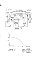
- FIG. 1 is a curve illustrating the Q vs. direct current field characteristics of a ferrite cored antenna winding
- FIG. Zillustrates an embodiment of my invention used in conjunction with a ferrite cored antenna
- FIG. 3 illustrates an embodiment of my invention used in conjunction with a ferrite cored intermediate frequency transformer
- FIG. 4 is another embodiment of my invention illus-- trating the use of a ferrite cored antenna, the impedance of which is compensated by the application of gain control power to a transistor connected in the input of the antenna;
- PEG. 5 illustrates still another embodiment of my invention in which self-saturating circuitry controls the impedance of a ferrite cored antenna and automatically provides partial gain control.
- the coil Q vs. direct current field characteristics of a ferrite loop antenna is illustrated in FIG. 1 on a semilogarithmic scale.
- the loop antenna had an unloaded Q of about 450 at the frequency of measurement.
- the antenna loop was fixed loaded to reduce the Q to about 300.
- the operating Q should be relatively high for pickup of weak signals. From FIG. 1 it may be observed that a current of 10 microamps flowing through the antenna loop drops the Q to about 50% and that a current in the order of 300 microamps drops the Q of the coil to about 20% of its loaded value. It was also observed that the tuning change in the range of from 10 to 300 microarnps was less than .1%. Since the drop in Q value represents a decrease in effective capture area of the loop, it may serve as a gain control while tending to maintain the correct load impedance.
- the antenna stage includes an antenna 11 ⁇ having a ground primary pickup winding 11 tuned by a variable condenser 12 and an aperiodic secondary winding 13 grounded for alternating cuurents by a condenser 14.
- winding 11 and the secondary winding 13 are wound on an elongated magnetic core 15, preferably made of a ferritevmaterial for relatively high Qs.
- the antenna loop 1s provided With a relatively high turns ratio to provide a very large impedance step down, e.g.,.the impedance of the primary winding 11 may be on the order of 350K ohms and the secondary Winding 13 about 1500 chars for coupling to a mixer having a low impedance input.
- Signals picked up 'by the antenna are passed from the secondary winding 13 to the base input circuit of a transistorized mixer having a base 21, an emitter 22 and a collector 23.
- Intermediate frequency signals are obtained in a conventional manner by means of the heterodyning action .of a local oscillator 24, the output ofwhich is applied to the emitter 22 through the emitterresistor load 25 and a parallel-connected condenser 26.
- the signals derived from the collector 23 of the mixer 26 are amplified in an intermediate frequency amplifier 30, grounded for alternatingcurrents by a condenser 31.
- the amplified signals are then coupled by means of condenser 32 across a tuned circuit 33 to a diode detector- 35.
- High frequency signals are bypassed to ground by meansof direct current blocking condensers 36' and 37, and audio signals are applied to audio amplifiers (not shown) through a transformer 38.
- the junction at the audio transformer 38 provides a D.-C. source of grain control power available for use in the novel manner taught by my invention.
- I apply automatic gain control power to the intermediate frequency stage from the junction 40 through resistors 42 and 43. I also apply automatic gain control power from the junction 40 to the input of the mixer stage transistor 26 through resistors 42 and 44, and through the lowimpedance secondary winding 13 of antenna 10'. To compensate for the resulting change in the input impedance of the mixer stage transistor 20 due to this application of gain control power, 1 apply to thehigh impedance primary winding 11 of antenna 10 a core-saturating current from the gain control power source 40 through.
- the input impedance of transistor 20 is altered over a wide range and the resulting change in impedance is reflected back from the secondary winding 13 to the primary winding 11 of transformer 10. This action reduces the load on the transformer 10 so thatboth the bandwidth and transfer characteristics of the transformer are seriously altered.
- a high Q ferrite cored antenna such as is illustrated in FIG. 1, the unloading of the transformer results in a circuit bandwidth reduction and a shift in resonant frequency to an extent that it may become the controlling element in the selectivity of the receiver. In some receivers ofthis type Without compensation, signals are actually lost and regained periodically to produce a flutter operation on strong input signals.
- I alter the characteristics of the ferrite rod by increasing the direct current bias flux on the rod and thus increase the level of saturation of the core. This results in a reduction in circuit Q, tending to compensate for the change in impedance and re-establish the receiver bandwith automatically. Because the saturating current applied to the transformer affects the Q to a much greater degree than the permeability, the resonant frequency of the transformer is substantially stabilized. Also, the decrease in Q effectively produces a stage of automatic gain control ahead of the first transistor stage, since the capture area of the antenna is reduced.
- FIG. 3 Both the primary Reference is now made to FIG. 3 in which my invention is illustrated in conjunction with a gain-controlled intermediate frequency amplifier stage.
- frequency signals derived froma mixer stage (not shown) are applied in the usual way to an intermediate frequency transformer '50, having a primary winding 51 fixed-tuned by a condenser 52, and a secondary winding 53 fixedtuned by a condenser 54 and grounded for alternating currents by a condenser 55.
- the transformer 50 also.ineludes an auxiliary winding 56, the connections and operations of which will be describeclin detail below.
- the output from transformer SO may be derived from a small, low impedance, tapped-down portion of secondary winding 53 and applied to the base input circuit of a transistorized intermediate frequency amplifier .60
- the amplifier '60 may be followedby any number of intermediate frequency amplifier stages indicated generally in block 64, and provided with operating bias from a source (not shown) through a resistor65.
- the output of the intermediate frequency amplifiers is then ape plied through a conventional tuned transformer 66 ,t o .a
- Audio signals may then .be passed through .an .audio. transformer 71, the primary 'of which is grounded an" intermediate frequency signals by means ofaD.-'C. block; ing condenser 72.
- the junction 73 Iconstitut'es stony ventional source of direct current automatic gainfcontrol power.
- FIG. 4 I employ a ferrite cored local oscillator 114, the output of which is applied toth e,
- the collector output from the mixer may then be amplified and detected in a conventional manner.
- I apply any convenient source of automatic gain control Intermediate While I have illustrated a separate additional satupower through resistors 12d and 121 and the low impedance secondary winding to the base 111 of transistor mixer 11%. Since (as in the previous embodiments) the impedance variations in the transistor mixer 11.9 are refiected back to the transformer ltlii, thereby causing a change in circuit characteristics, I also apply current to the primary winding Ill-1 of the transformer Tilt in a manner to compensate for impedance changes. In this embodiment current is applied through the emitter 123 and the collector 124 of an auxiliary saturation-controlling transistor 125.
- Bascemitter bias for the transistor 125 is provided by connecting the base 126 and the emitter 123 across the resistor 121), and the emitter circuit is completed :to ground through a resistor 127.
- transistor 125 is driven by the received signal, and it level of operation is controlled by the automatic gain control.
- This arrangement takes advantage of the amplification of the transistor 125, thus permitting faster control, and it may even be used to over-compensate.
- this arrangement provides a stage of gain control ahead of the mixer stage and alone may suifice in many applications to provide adequate gain control performance.
- FIG. 5 The embodiment illustrated in FIG. 5 is identical with that of FIG. 4, with the exception that saturating currents for the transformer core are obtained without the benefit of transistor 12%; instead, an additional saturated winding 13d is wound on the magnetic core and connected in series with a rectifier 131 and parallel-connected resistor 132 and condenser 133. Radio frequency signals picked up at the antenna transformer Tilt are also applied to the saturating winding 1313 and converted to direct current by the rectifier 131.
- the degree of direct current saturation of the ferrite core of the transformer 1th will vary in proportion to the strength of the received signals.
- increased radio frequency signals received at the antenna 184) will cause an attendant increase in automatic gain control power applied to the base input circuit of mixer 110. As in the other embodiments, this results in an unloading of the antenna.
- the current flowing through the saturating winding 13% compensates for this unloading in two ways; first, the direct currents produced by the rectifier 131 tend to reduce the antenna Q, thereby providing partial gain control ahead of both the antenna and the mixer stages and, in addition, the reduction in Q tends to compensate for the change in impedance resulting in the mixer stage.
- the combination comprising: a high Q transformer tuned to a predetermined resonant frequency and having a predetermined bandwidth, said transformer having a high impedance input winding and a relatively low impedance output winding both wound on a aturable magnetic core; a variable impedance device having a low impedance input circuit connected across said low impedance output winding; a source of direct current power for varying the input impedance of said variable impedance device in accordance with a varying condition; and means controlled by said source of direct current power for adjusting the degree of saturation of said core for compensating for variations of impedance of said input circuit, thereby maintaining substantially constant said predetermined resonant frequency and tending to increase said bandwidth with increased power from said source.
- variable impedance device comprises an electronic valve having an input electrode, an output electrode and an electrode common to said input and said output electrodes, said low impedance output winding being connected across said input electrode and said common electrode, and wherein said source of direct current power comprises a source of automatic gain control connected to said input electrode.
- said electronic valve comprises a transistor and wherein said input, output and common electrodes comprise, respectively, a base, a collector and an emitter electrode.
- said means adjusting the degree of saturation of said core comprises an auxiliary winding mounted on said core and connected to said source.
- said means adjusting the saturation of said core comprises an auxiliary winding on said core and a rectifier connected in a series loop with said auxiliary winding.
- said means adjusting the saturation of said core comprises an auxiliary transistor having base, emitter and collector electrodes, said emitter and collector electrodes being connected in a series loop with said primary winding and said source.
- a radio receiver for processing radio frequency signals, the combination comprising: a first transistor amplifier for amplifying said radio frequency signals, said first transistor having base, emitter, and collector electrodes; an input circuit between said base and emitter electrodes; a transformer having a primary winding and a secondary winding both Wound on a saturable magnetic core; means connecting said secondary winding across said input circuit of said first transistor; a second transistor having base, emitter, and collector electrodes, the collector and emitter electrodes of said second transistor being connected in series with said primary winding and first and second resistors; a source of automatic gain control voltage connected across said first and second resistors, said automatic gain control voltage being a direct voltage proportional to the magnitude of said signal; a connection from the base of said first transistor to the junction of said first and second resistors for controlling the gain of said first transistor in inverse relationship to the magnitude of said signal; and a connection from the base of said second transistor to said junction for controlling the conductivity of said second transistor in inverse relationship to the magnitude of said signal whereby
Landscapes
- Input Circuits Of Receivers And Coupling Of Receivers And Audio Equipment (AREA)
- Amplifiers (AREA)
Description
Feb. 19, 1963 E. J. H- BUSSARD Filed Sept. 5, 1958 l. FAMPLIFIER 2 Sheets-Sheet 1 I5 43 H I FERRl TE Au 'rz u nA g igg STAGE 0 OSCILLATOR STAGE M M 0 |.'o 1'0 160 1600 u. AMPS.
INVENTOR.
EMMERY J. H. BUSSARD.
AT TO Feb. 19, 1963 E.-J. H. BUSSARD 3,078,420
AUTOMATIC FERRITE LOOP ANTENNA LOADING Filed Sept. 5, 1958 2 Sheets-Sheet 2 52 AMPLIFIER A.G.C FR OM DETECTOR E STAGE FROM MIXER STAGE T ANTENNA FERRITE l g STAGE CORE IOO I00 H0 H3 MIXER STAGE FERRITE CORE ll6 ANTENNA STAGE LOCAL LOCAL I OSCiLLATOR. OSCILLATOR 5 N4 '32 I33 L. ||4
INVENTOR EMMERY J. H. BUSSARD.
ATTOR YS.
3,073,420 AUTOMATI IC FEREHTE L? ANTENNA LGADEN G Emmery J. H. Bussard, Cincinnati, (Bhio, assignor to Avco Manufacturing Corporation, (Cincinnati, @hio, a corporation of Delaware Filed Sept. 5, i958, Ser. No. 759,267 8 Claims. (Cl. 339-29) This invention relates to a system and apparatus for compensating for the unloading of a transformer resulting from the application of gain control, and particularly for compensating the unloading of high frequency ferrite cored transformers employed as couplers to transistor mixers and amplifiers.
As is well known in the art, the input impedance of a transistor which is gaincontrolledby a negative-going voltage varies over a wide range with automatic gain control drive. In many applications the transistor may be driven essentially to cutoff bias under normal operating conditions for the desired control range. Input impedance changes greater than 10 to 1 may be obtained with normal automatic gain control of a transistorized mixer, and even greaterimpedance changes have been observed in gain-controlled transistorized amplifier stages.
' The change in transistor input impedance resulting from gain control is reflected into the driving transformer, thereby changing its load such that the bandwidth and transfer characteristics are seriously altered. This is especially true with high Q devices, such as ferrite cored antenna loops and ferrite cored intermediate frequency transformers. The unloading due to gain control drive in antennae and intermediate frequency transformers can result in a frequency shift and a circuit bandwidth reduction to the extent that the transformer becomes the controlling element in the se.ectivity of the amplifier. On the other'hand, good receiver operation requires that the center frequency remain substantially constant while the bandwidth should increase with increased signal strength for better audio fidelity.
It is also known that the characteristics of certain magnetic materials can be altered by superimposing an electric field on the material to alter the degree of saturation; furthermore, it has been observed that with certain magnetic materials, such as ferrites, the Q factor is effected much more than the permeability factor (mu) as the saturation of the core is increased. I use this peculiar characteristic to provide an automatically controlled circuit Q with increased signal input to the antenna Without serious circuit detuning. In fact, the detuning which results from core saturation is used to compensate for the opposite detuning caused by the increased transistor input impedance. In addition, I automatically increase the bandwidth of the tuned circuits, thus improving fidelity. Careful, though not critical, adjustment results in stable transformer operation with variation of signal input level over a wide operating range.
Thus, by means of this invention I compensate for impedance change in the transistor input circuit resulting from increased automatic gain control by providing an auxiliary compensating voltage for altering the state or degree of saturation of the antenna or intermediate frequency transformer core.
The principal object of this invention is to provide automatic compensation for impedance change due to variable loading of a magnetic cored transformer resulting from changes in level of the automatic gain control.
Another object of this invention is the provision of automatic means for band-pass increase with increased signal strength to provide improved high frequency audio response.
Another object of this invention is to provide means for United rates i atent ice automatic gain control of signal intensity to the input transistor.
One illustrated embodiment of my invention is employed in conjunction with an antenna provided with an elongated ferrite core and having its output connected across the input of a transistor mixer supplied with a source of negative-going automatic gain control. To compensate for changes in the antenna loading due to the variation in level of the automatic gain control, I provide means for changing the degree of saturation of the ferrite core in accordance with the varying automatic gain control current. I thereby compensate for changes in frequency, Q and inductance, and produce stable operation of the system.
A second embodiment illustrates the operation of my invention in conjunction with a gain-controlled intermedi ate frequency amplifier driven by the output of a magnetic cored intermediate frequency transformer. As in the first embodiment, the degree of saturation of the transformer is automatically adjusted in accordance with the level of the automatic gain control applied to the transistor input, thereby compensating for changes in frequency, Q and inductance.
Another embodiment of my invention employs a gaincontrollcd transistor connected to the input of a ferrite cored antenna and thus accelerates the degree of core saturation and compensates for the change in antenna impedance.
Another embodiment of my invention employs a ferrite cored antenna which is self-loaded to control impedance rise and automatically provide partial gain control.
For a more complete understanding of the nature and further objects of my invention, reference should now be made to thefollowing detailed description and to the accompanying drawings, in which:
FIG. 1 is a curve illustrating the Q vs. direct current field characteristics of a ferrite cored antenna winding;
FIG. Zillustrates an embodiment of my invention used in conjunction with a ferrite cored antenna;
FIG. 3 illustrates an embodiment of my invention used in conjunction with a ferrite cored intermediate frequency transformer;
FIG. 4 is another embodiment of my invention illus-- trating the use of a ferrite cored antenna, the impedance of which is compensated by the application of gain control power to a transistor connected in the input of the antenna; and
. PEG. 5 illustrates still another embodiment of my invention in which self-saturating circuitry controls the impedance of a ferrite cored antenna and automatically provides partial gain control.
The coil Q vs. direct current field characteristics of a ferrite loop antenna, such as is commonly used in radio broadcast receivers, is illustrated in FIG. 1 on a semilogarithmic scale. In the specific example depicted the loop antenna had an unloaded Q of about 450 at the frequency of measurement. To obtain a plot, the antenna loop was fixed loaded to reduce the Q to about 300. As is known, the operating Q should be relatively high for pickup of weak signals. From FIG. 1 it may be observed that a current of 10 microamps flowing through the antenna loop drops the Q to about 50% and that a current in the order of 300 microamps drops the Q of the coil to about 20% of its loaded value. It was also observed that the tuning change in the range of from 10 to 300 microarnps was less than .1%. Since the drop in Q value represents a decrease in effective capture area of the loop, it may serve as a gain control while tending to maintain the correct load impedance.
Referring to FIG. 2, there is schematically shown a portion of superheterodyne receiver having antenna and mixer stages incorporating my invention, and conventional intermediate frequency and detector stages. The antenna stage includes an antenna 11} having a ground primary pickup winding 11 tuned by a variable condenser 12 and an aperiodic secondary winding 13 grounded for alternating cuurents by a condenser 14. winding 11 and the secondary winding 13 are wound on an elongated magnetic core 15, preferably made of a ferritevmaterial for relatively high Qs. The antenna loop 1s provided With a relatively high turns ratio to provide a very large impedance step down, e.g.,.the impedance of the primary winding 11 may be on the order of 350K ohms and the secondary Winding 13 about 1500 chars for coupling to a mixer having a low impedance input.
Signals picked up 'by the antenna are passed from the secondary winding 13 to the base input circuit of a transistorized mixer having a base 21, an emitter 22 and a collector 23. Intermediate frequency signals are obtained in a conventional manner by means of the heterodyning action .of a local oscillator 24, the output ofwhich is applied to the emitter 22 through the emitterresistor load 25 and a parallel-connected condenser 26. The signals derived from the collector 23 of the mixer 26 are amplified in an intermediate frequency amplifier 30, grounded for alternatingcurrents by a condenser 31. The amplified signals are then coupled by means of condenser 32 across a tuned circuit 33 to a diode detector- 35. High frequency signals are bypassed to ground by meansof direct current blocking condensers 36' and 37, and audio signals are applied to audio amplifiers (not shown) through a transformer 38. The junction at the audio transformer 38 provides a D.-C. source of grain control power available for use in the novel manner taught by my invention.
I apply automatic gain control power to the intermediate frequency stage from the junction 40 through resistors 42 and 43. I also apply automatic gain control power from the junction 40 to the input of the mixer stage transistor 26 through resistors 42 and 44, and through the lowimpedance secondary winding 13 of antenna 10'. To compensate for the resulting change in the input impedance of the mixer stage transistor 20 due to this application of gain control power, 1 apply to thehigh impedance primary winding 11 of antenna 10 a core-saturating current from the gain control power source 40 through.
In operation, as gain control power is applied to the base 21, the input impedance of transistor 20 is altered over a wide range and the resulting change in impedance is reflected back from the secondary winding 13 to the primary winding 11 of transformer 10. This action reduces the load on the transformer 10 so thatboth the bandwidth and transfer characteristics of the transformer are seriously altered. With a high Q ferrite cored antenna, such as is illustrated in FIG. 1, the unloading of the transformer results in a circuit bandwidth reduction and a shift in resonant frequency to an extent that it may become the controlling element in the selectivity of the receiver. In some receivers ofthis type Without compensation, signals are actually lost and regained periodically to produce a flutter operation on strong input signals.
By applying current from the junction 40 throughresistors 42 and 45 to the primary winding 11 of transformer 10, I alter the characteristics of the ferrite rod by increasing the direct current bias flux on the rod and thus increase the level of saturation of the core. This results in a reduction in circuit Q, tending to compensate for the change in impedance and re-establish the receiver bandwith automatically. Because the saturating current applied to the transformer affects the Q to a much greater degree than the permeability, the resonant frequency of the transformer is substantially stabilized. Also, the decrease in Q effectively produces a stage of automatic gain control ahead of the first transistor stage, since the capture area of the antenna is reduced.
Both the primary Reference is now made to FIG. 3 in which my invention is illustrated in conjunction with a gain-controlled intermediate frequency amplifier stage. frequency signals derived froma mixer stage (not shown) are applied in the usual way to an intermediate frequency transformer '50, having a primary winding 51 fixed-tuned by a condenser 52, and a secondary winding 53 fixedtuned by a condenser 54 and grounded for alternating currents by a condenser 55. The transformer 50 also.ineludes an auxiliary winding 56, the connections and operations of which will be describeclin detail below.
The output from transformer SOmay be derived from a small, low impedance, tapped-down portion of secondary winding 53 and applied to the base input circuit of a transistorized intermediate frequency amplifier .60
having a base 61, a grounded emitter 62 and a collector 63L Depending 'upon the gain requirements of the system, the amplifier '60 may be followedby any number of intermediate frequency amplifier stages indicated generally in block 64, and provided with operating bias from a source (not shown) through a resistor65. The output of the intermediate frequency amplifiers is then ape plied through a conventional tuned transformer 66 ,t o .a
Audio signals may then .be passed through .an .audio. transformer 71, the primary 'of which is grounded an" intermediate frequency signals by means ofaD.-'C. block; ing condenser 72. The junction 73 Iconstitut'es stony ventional source of direct current automatic gainfcontrol power.
For applying the automatic gain ,control .power tothe intermediate frequency amplifier 60 I .providea direct current path to the transistor base 61 from thejunction v 73 through resistors and 81 and the small tapped-.
down portion of winding 53. Since the application of gain controlpower to the base '61 increases the input impedance of the transistor 69 andQhence, unloads the intermediate frequency transformer 50, the Q and bandwidth characteristics of the intermediatefrequency transformer are seriously altered and the transformer is de tuned and the bandwidth is narrowed.
In order to compensate for detuning, to increase the bandwidth, and to avoid attendant loss of power in the amplifier stages, I also apply gain control power from the junction 73 to the saturating winding 56 through the re- 7 sisters 80 and 82. As in the embodiment illustrated in FIG. 2, this has the effect of compensating for the ,unloading due to gain control applied to the transistor input. rating winding 56 in this embodiment, it is to be clearly understood that similar advantageous results will also be achieved under many circumstances byeliminating the winding 56 and connecting the resistor 82 directly to the primary winding 51, provided thedirect current bias for the preceeding driver stage (not shown does not flow through the winding 51. Also, this same control ,may
be applied to asmany of the intermediate frequency stages as may be required.
In the embodiment of FIG. 4 I employ a ferrite cored local oscillator 114, the output of which is applied toth e,
I apply any convenient source of automatic gain control Intermediate While I have illustrated a separate additional satupower through resistors 12d and 121 and the low impedance secondary winding to the base 111 of transistor mixer 11%. Since (as in the previous embodiments) the impedance variations in the transistor mixer 11.9 are refiected back to the transformer ltlii, thereby causing a change in circuit characteristics, I also apply current to the primary winding Ill-1 of the transformer Tilt in a manner to compensate for impedance changes. In this embodiment current is applied through the emitter 123 and the collector 124 of an auxiliary saturation-controlling transistor 125. Bascemitter bias for the transistor 125 is provided by connecting the base 126 and the emitter 123 across the resistor 121), and the emitter circuit is completed :to ground through a resistor 127. Thus, transistor 125 is driven by the received signal, and it level of operation is controlled by the automatic gain control. This arrangement takes advantage of the amplification of the transistor 125, thus permitting faster control, and it may even be used to over-compensate. Moreover, this arrangement provides a stage of gain control ahead of the mixer stage and alone may suifice in many applications to provide adequate gain control performance.
The embodiment illustrated in FIG. 5 is identical with that of FIG. 4, with the exception that saturating currents for the transformer core are obtained without the benefit of transistor 12%; instead, an additional saturated winding 13d is wound on the magnetic core and connected in series with a rectifier 131 and parallel-connected resistor 132 and condenser 133. Radio frequency signals picked up at the antenna transformer Tilt are also applied to the saturating winding 1313 and converted to direct current by the rectifier 131. Since only direct current flows through the saturating winding 130 and since the magnitude of the direct current through the winding 130 is proportional to the ma nitude of the radio fre uenc signals, the degree of direct current saturation of the ferrite core of the transformer 1th) will vary in proportion to the strength of the received signals. In the operation of this embodiment, increased radio frequency signals received at the antenna 184) will cause an attendant increase in automatic gain control power applied to the base input circuit of mixer 110. As in the other embodiments, this results in an unloading of the antenna. The current flowing through the saturating winding 13% compensates for this unloading in two ways; first, the direct currents produced by the rectifier 131 tend to reduce the antenna Q, thereby providing partial gain control ahead of both the antenna and the mixer stages and, in addition, the reduction in Q tends to compensate for the change in impedance resulting in the mixer stage.
While in each of the illustrated embodiments my invention is described in conjunction with a transistorized receiver, the invention is equally applicable to other types of equipment and is also useful in conjunction with other types of semiconductors. In fact, the invention may even be useful under certain conditions with vacuum tubes. Also, if more automatic gain control power is required in special cases than can reasonably be obtained from the circuitry illustrated in FIGS. 2 and 3, then a direct current amplifier may be used after the detector. It is my intention, therefore, that my invention be limited only by the scope of the following claims as interpreted in the light of the prior art.
I claim:
1. The combination comprising: a high Q transformer tuned to a predetermined resonant frequency and having a predetermined bandwidth, said transformer having a high impedance input winding and a relatively low impedance output winding both wound on a aturable magnetic core; a variable impedance device having a low impedance input circuit connected across said low impedance output winding; a source of direct current power for varying the input impedance of said variable impedance device in accordance with a varying condition; and means controlled by said source of direct current power for adjusting the degree of saturation of said core for compensating for variations of impedance of said input circuit, thereby maintaining substantially constant said predetermined resonant frequency and tending to increase said bandwidth with increased power from said source.
2. The invention as defined in claim 1 wherein said core is comprised of a ferrite material.
3. The invention as defined in claim 1 wherein said variable impedance device comprises an electronic valve having an input electrode, an output electrode and an electrode common to said input and said output electrodes, said low impedance output winding being connected across said input electrode and said common electrode, and wherein said source of direct current power comprises a source of automatic gain control connected to said input electrode.
4. The invention as defined in claim 3 wherein said electronic valve comprises a transistor and wherein said input, output and common electrodes comprise, respectively, a base, a collector and an emitter electrode.
5. The invention as defined in claim 1 wherein said means adjusting the degree of saturation of said core comprises an auxiliary winding mounted on said core and connected to said source.
6. The invention as defined in claim 1 wherein said means adjusting the saturation of said core comprises an auxiliary winding on said core and a rectifier connected in a series loop with said auxiliary winding.
7. The invention as defined in claim 1 wherein said means adjusting the saturation of said core comprises an auxiliary transistor having base, emitter and collector electrodes, said emitter and collector electrodes being connected in a series loop with said primary winding and said source.
8. In a radio receiver for processing radio frequency signals, the combination comprising: a first transistor amplifier for amplifying said radio frequency signals, said first transistor having base, emitter, and collector electrodes; an input circuit between said base and emitter electrodes; a transformer having a primary winding and a secondary winding both Wound on a saturable magnetic core; means connecting said secondary winding across said input circuit of said first transistor; a second transistor having base, emitter, and collector electrodes, the collector and emitter electrodes of said second transistor being connected in series with said primary winding and first and second resistors; a source of automatic gain control voltage connected across said first and second resistors, said automatic gain control voltage being a direct voltage proportional to the magnitude of said signal; a connection from the base of said first transistor to the junction of said first and second resistors for controlling the gain of said first transistor in inverse relationship to the magnitude of said signal; and a connection from the base of said second transistor to said junction for controlling the conductivity of said second transistor in inverse relationship to the magnitude of said signal whereby the current flow in said series loop including said first and second resistors, the emitter and collector electrodes of said second transistor and said primary winding is controlled by said source and whereby the degree of saturation of said magnetic core is varied as the gain of said first transistor is controlled.
References Cited in the file of this patent UNITED STATES PATENTS 2,714,187 Goodrich July 26, 1955 2,750,452 Goodrich June 12, 1956 2,773,945 Theriault Dec. 11, 1956 2,774,866 Burger Dec. 18, 1956 2,853,602 Farber Sept. 23, 1958 2,878,380 Holmes Mar. 17, 1959 2,891,146 Sciwba June 16, 1959 2,897,353 Schweiss July 28, 1959
Claims (1)
1. THE COMBINATION COMPRISING: A HIGH Q TRANSFORMER TUNED TO A PREDETERMINED RESONANT FREQUENCY AND HAVING A PREDETERMINED BANDWIDTH, SAID TRANSFORMER HAVING A HIGH IMPEDANCE INPUT WINDING AND A RELATIVELY LOW IMPEDANCE OUTPUT WINDING BOTH WOUND ON A SATURABLE MAGNETIC CORE; A VARIABLE IMPEDANCE DEVICE HAVING A LOW IMPEDANCE INPUT CIRCUIT CONNECTED ACROSS SAID LOW IMPEDANCE OUTPUT WINDING; A SOURCE OF DIRECT CURRENT POWER FOR VARYING THE INPUT IMPEDANCE OF SAID VARIABLE IMPEDANCE DEVICE IN ACCORDANCE WITH A VARYING CONDITION; AND MEANS CONTROLLED BY SAID SOURCE OF DIRECT CURRENT POWER FOR ADJUSTING THE
Priority Applications (1)
| Application Number | Priority Date | Filing Date | Title |
|---|---|---|---|
| US759267A US3078420A (en) | 1958-09-05 | 1958-09-05 | Automatic ferrite loop antenna loading |
Applications Claiming Priority (1)
| Application Number | Priority Date | Filing Date | Title |
|---|---|---|---|
| US759267A US3078420A (en) | 1958-09-05 | 1958-09-05 | Automatic ferrite loop antenna loading |
Publications (1)
| Publication Number | Publication Date |
|---|---|
| US3078420A true US3078420A (en) | 1963-02-19 |
Family
ID=25055021
Family Applications (1)
| Application Number | Title | Priority Date | Filing Date |
|---|---|---|---|
| US759267A Expired - Lifetime US3078420A (en) | 1958-09-05 | 1958-09-05 | Automatic ferrite loop antenna loading |
Country Status (1)
| Country | Link |
|---|---|
| US (1) | US3078420A (en) |
Cited By (4)
| Publication number | Priority date | Publication date | Assignee | Title |
|---|---|---|---|---|
| US3254306A (en) * | 1962-11-21 | 1966-05-31 | Rca Corp | Automatic gain control circuit for amplifiers |
| US6259325B1 (en) * | 1998-11-25 | 2001-07-10 | Kabushiki Kaisha Toshiba | Single-ended signals to differential signals converter |
| US20130141167A1 (en) * | 2011-12-05 | 2013-06-06 | Samsung Electro-Mechanics Co., Ltd. | Power amplifier |
| US8558605B1 (en) * | 2012-08-27 | 2013-10-15 | Linear Technology Corporation | Frequency mixer topology providing high linearity, low noise and high gain |
Citations (8)
| Publication number | Priority date | Publication date | Assignee | Title |
|---|---|---|---|---|
| US2714187A (en) * | 1951-07-02 | 1955-07-26 | Rca Corp | Variable high frequency coupling transformer |
| US2750452A (en) * | 1951-03-21 | 1956-06-12 | Rca Corp | Selectivity control circuit |
| US2773945A (en) * | 1955-10-05 | 1956-12-11 | Rca Corp | Transistor signal amplifying circuits |
| US2774866A (en) * | 1956-01-30 | 1956-12-18 | Emerson Radio & Phonograph Cor | Automatic gain and band width control for transistor circuits |
| US2853602A (en) * | 1956-09-27 | 1958-09-23 | Hazeltine Research Inc | Frequency-converter system having mixer and local oscillator gain controlled in opposite sense |
| US2878380A (en) * | 1956-11-30 | 1959-03-17 | Rca Corp | Push-pull signal amplifier |
| US2891146A (en) * | 1956-12-07 | 1959-06-16 | Motorola Inc | Manual volume control for transistor audio stage utilizing both variable attenuationand variable degeneration |
| US2897353A (en) * | 1955-10-20 | 1959-07-28 | Philco Corp | Non-linear device varying impedance match between antenna and radio frequency stages |
-
1958
- 1958-09-05 US US759267A patent/US3078420A/en not_active Expired - Lifetime
Patent Citations (8)
| Publication number | Priority date | Publication date | Assignee | Title |
|---|---|---|---|---|
| US2750452A (en) * | 1951-03-21 | 1956-06-12 | Rca Corp | Selectivity control circuit |
| US2714187A (en) * | 1951-07-02 | 1955-07-26 | Rca Corp | Variable high frequency coupling transformer |
| US2773945A (en) * | 1955-10-05 | 1956-12-11 | Rca Corp | Transistor signal amplifying circuits |
| US2897353A (en) * | 1955-10-20 | 1959-07-28 | Philco Corp | Non-linear device varying impedance match between antenna and radio frequency stages |
| US2774866A (en) * | 1956-01-30 | 1956-12-18 | Emerson Radio & Phonograph Cor | Automatic gain and band width control for transistor circuits |
| US2853602A (en) * | 1956-09-27 | 1958-09-23 | Hazeltine Research Inc | Frequency-converter system having mixer and local oscillator gain controlled in opposite sense |
| US2878380A (en) * | 1956-11-30 | 1959-03-17 | Rca Corp | Push-pull signal amplifier |
| US2891146A (en) * | 1956-12-07 | 1959-06-16 | Motorola Inc | Manual volume control for transistor audio stage utilizing both variable attenuationand variable degeneration |
Cited By (5)
| Publication number | Priority date | Publication date | Assignee | Title |
|---|---|---|---|---|
| US3254306A (en) * | 1962-11-21 | 1966-05-31 | Rca Corp | Automatic gain control circuit for amplifiers |
| US6259325B1 (en) * | 1998-11-25 | 2001-07-10 | Kabushiki Kaisha Toshiba | Single-ended signals to differential signals converter |
| US20130141167A1 (en) * | 2011-12-05 | 2013-06-06 | Samsung Electro-Mechanics Co., Ltd. | Power amplifier |
| US8952755B2 (en) * | 2011-12-05 | 2015-02-10 | Samsung Electro-Mechanics Co., Ltd. | Power amplifier |
| US8558605B1 (en) * | 2012-08-27 | 2013-10-15 | Linear Technology Corporation | Frequency mixer topology providing high linearity, low noise and high gain |
Similar Documents
| Publication | Publication Date | Title |
|---|---|---|
| US2774866A (en) | Automatic gain and band width control for transistor circuits | |
| US4322856A (en) | Double superheterodyne tuner for receiving television aural signals | |
| US2302893A (en) | Variable inductance arrangement | |
| US2773945A (en) | Transistor signal amplifying circuits | |
| US2750452A (en) | Selectivity control circuit | |
| US3078420A (en) | Automatic ferrite loop antenna loading | |
| US3205444A (en) | Automatic gain control circuit with signal overload prevention | |
| US3038072A (en) | Automatic-gain and bandwidth control system for transistor circuits | |
| US2627022A (en) | Combined video gain and frequency response control | |
| US3303428A (en) | Manual or automatic transistor r. f. gain control system utilizing a voltage controlled variable resistance element | |
| US2281661A (en) | Tuning system | |
| US4972353A (en) | Radio-frequency transformer providing automatic gain control and overload protection | |
| US2280605A (en) | Piezoelectric crystal filter circuit | |
| US3258695A (en) | Reflex receiver | |
| US4048569A (en) | Receiver automatic gain control system | |
| US2794909A (en) | Cathode follower radio frequency amplifier for radio receiver | |
| US2088229A (en) | Automatic fidelity control circuit | |
| US3872393A (en) | If amplifier | |
| US2312139A (en) | Stabilized regenerative circuits | |
| US2033986A (en) | Frequency converter | |
| US2983815A (en) | Automatic gain control | |
| US3823379A (en) | Television automatic gain control circuitry providing for compatible control of vhf tuner and uhf tuner | |
| US2504175A (en) | Contrast control circuit for television systems | |
| US2216582A (en) | Automatic volume control with noise suppression | |
| US2787704A (en) | Constant band-width input stage with high q antenna |