US3044194A - Truck-mounted trench excavating machine - Google Patents
Truck-mounted trench excavating machine Download PDFInfo
- Publication number
- US3044194A US3044194A US793118A US79311859A US3044194A US 3044194 A US3044194 A US 3044194A US 793118 A US793118 A US 793118A US 79311859 A US79311859 A US 79311859A US 3044194 A US3044194 A US 3044194A
- Authority
- US
- United States
- Prior art keywords
- boom
- trench
- chain
- shaft
- chassis
- Prior art date
- Legal status (The legal status is an assumption and is not a legal conclusion. Google has not performed a legal analysis and makes no representation as to the accuracy of the status listed.)
- Expired - Lifetime
Links
Images


Classifications
-
- E—FIXED CONSTRUCTIONS
- E02—HYDRAULIC ENGINEERING; FOUNDATIONS; SOIL SHIFTING
- E02F—DREDGING; SOIL-SHIFTING
- E02F5/00—Dredgers or soil-shifting machines for special purposes
- E02F5/02—Dredgers or soil-shifting machines for special purposes for digging trenches or ditches
- E02F5/06—Dredgers or soil-shifting machines for special purposes for digging trenches or ditches with digging elements mounted on an endless chain
-
- E—FIXED CONSTRUCTIONS
- E02—HYDRAULIC ENGINEERING; FOUNDATIONS; SOIL SHIFTING
- E02F—DREDGING; SOIL-SHIFTING
- E02F5/00—Dredgers or soil-shifting machines for special purposes
- E02F5/02—Dredgers or soil-shifting machines for special purposes for digging trenches or ditches
- E02F5/14—Component parts for trench excavators, e.g. indicating devices travelling gear chassis, supports, skids
- E02F5/145—Component parts for trench excavators, e.g. indicating devices travelling gear chassis, supports, skids control and indicating devices
-
- Y—GENERAL TAGGING OF NEW TECHNOLOGICAL DEVELOPMENTS; GENERAL TAGGING OF CROSS-SECTIONAL TECHNOLOGIES SPANNING OVER SEVERAL SECTIONS OF THE IPC; TECHNICAL SUBJECTS COVERED BY FORMER USPC CROSS-REFERENCE ART COLLECTIONS [XRACs] AND DIGESTS
- Y10—TECHNICAL SUBJECTS COVERED BY FORMER USPC
- Y10S—TECHNICAL SUBJECTS COVERED BY FORMER USPC CROSS-REFERENCE ART COLLECTIONS [XRACs] AND DIGESTS
- Y10S37/00—Excavating
- Y10S37/907—Automatic leveling excavators
Definitions
- the accurate formation of the trench therefore depends entirely upon the adroitness and :attentiveness of the operator
- the boom, together with the excavating chain is disposed between the tracks of the machine, while in other-s it is disposed laterally of the tracks. Neither type, however, permits any change or adjustment of such arrangement of the boom.
- a further object of the invention is to provide a trench exca vating machine for digging a trench with vertical walls and a uniform ybottom which may also have a predetermined incline and which will carry out such an operation automatically and independently of any particular skill or attentiveness of the operator.
- Another object of the invention is to provide such a machine which permits an adjustment of the boom and trenching chain so that the trench to be excavated may be either between the tracks fof the machine or laterally thereof.
- Another important advantage of the invention consists in the fact that, since the excavating operation proceeds automatically, the driver of the machine may concentrate his attention entirely upon the proper steering of the tractor along a prescribed cource which also determines the course of the trench to be dug and which may be either straight or curved.
- Still another object of the present invention is to provide a .trench excavating machine in which the trenching chain is protected from being overloaded when meeting solid rock or other -obstacles in the soil, and which is adapted to overcome such obstacles.
- the machine according to the invention is further ladapted to refill and level the trenches previously excavated thereby.
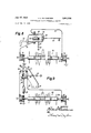
- FIGURE 2 shows a perspective rear view of the machine
- FIGURE 3 rshows a diagrammatic side view of the rear part of the machine with the trenching chain and control mechanism thereon;
- FIGURE 4 shows a diagrammatic rear view of the machine
- FIGURE 5 shows a cross section Itaken along line V--V of FIGURE 4.
- FIGURE 6 shows a perspective view of a part of the machine ywith a mechanism for controlling the operation of the boom in the event of an overload upon the trenching chain;
- FIGURE 7 shows a perspective view of an upright -bracket for supporting the hydraulic means for adjusting the boom and the trenching chain;
- FIGURE 8 is a diagrammatic illustration partly in perspective of the automatic elevation or depth control unit for ythe boom; while FIGURE 9 is a diagrammatic illustration, partly in perspective, of the control unit for adjusting the vertical position of the boom and trenching chain.
- a tractor which preferably runs on full tracks carries a boom 2 which is mounted on the rear end of the tractor and is provided with an endless trenching chain 3.
- Boom 2 is secured to a strong crossbar 6 forming a tubular shaft which is rotatably mounted on or within two bearings 4 and 5 and in which a drive shaft 7 is rotatably mounted which carries near one end a sprocket wheel 8 for driving the trenching chain 3 and on the other end a bevel gear 9 which, as shown in FIGURE 5, is in mesh with a bevel gear 10 which is driven by the engine of tractor 1 through a shaft 11.
- the chassis 12 of the tractor carries a bearing bracket 13 for supporting a trunnion 113 on the gear housing 14 of bevel gears 9 and 10.
- Shaft 11 of the driven bevel gear 10 exten-ds through trunnion 113, thus permitting the gear housing to be pivoted about the longitudinal axis of the trunnion.
- Bearing 4 is secured to the tubular shaft 6l.
- a substantially upright supporting bracket 15 is mounted which, as shown particularly iny FIGURES 2 and 7, is provided with an arcuate guideway 16 with a center of curvature coinciding with the axis of shaft 11.
- a guide plate 17 is slidable along guideway 16 and secured to the bearing 5 of tubular shaft 6.
- This tubular shaft 6 consists of several parts which are secured to each other by flanges 18 so that, when the flanges are disconnected, the individual parts of shaft 6 may be removed and replaced by shorter or longer parts.
- the trenching chain 3 may therefore be mounted either between the tracks of the tractor or at one side thereof.
- Shaft 7 which is driven by the tractor engine through shaft 11 and extends through the tubular shaft 6 for driving the trenching chain 3 through sprocket wheel 8 may likewise be rexchanged for a longeror shorter shaft in accordance with the length of tubular shaft 6.
- Boom 2, however, which forms an elongated supporting frame, is not adjustable in length.
- boom 2 also has a sprocket wheel 20 rotatably mounted at its lower end for supporting the trenching chain.
- the framelike boom 2 is rigidly secured to the tubular shaft 6 so that, when the latter is turned about its axis, boom 2 with trenching chain 3- thereon will be pivoted about the axis of shaft 6 permitting the working depth ofthe boom and chain to be adjusted.
- Shaft 7 further carries a sprocket wheel 21 for driving preliminary feed screw 24 through a chain 22 and a sprocket wheel 23.
- This feed screw 24 is'mounted on a shorter boom 2S which is pivotably suspended on tubular shaft 6 and drawn toward the rear by a spring 27, as shown in FIGURE l.
- Feed screw 24 divides the excavated soil which collects immediately in front of chain 3 and passes it to one or two other feed screws 26 which then convey the soil either toward one or both sides and pile and pack it together into banks orparapets D, as shown in FIGURE 2.
- Feed screws 26 are removably secured to a shaft 28 which is mounted on boom 2 and they are driven by the lower Stringer 3i? of trenching chain 3 through sprocket wheels 29, as shown in FIGURE 3.
- Feed screws 26 may be mounted either on one or both sides of shaft 2S.
- boom 2 further carries a supporting rail 31 on the lower end of which a scraper blade 33 is mounted.
- This scraper 33 is slidably adjustable on rail 31 by a bolt 34 extending through a longitudinal slot so as always to rest on the trench bottom S regardless of the, inclination of boom 2. It is also connected to boom 2 so as to be easily exchanged for another blade.
- the back of supporting rail 31 carries straps or brack- V ets 35 supporting a chute 36 through which, for example, short drainage pipes or other objects which are to be laid into the trench may be passed toward the bottom thereof.
- Brackets 35 for chute 36 may be designed in the form of arms which may be pivotably connected to rail 31 and chute 36 so as to permit the chute to be inclined to different angles relative to boom 2.V
- the chute may always be maintained at substantially the same inclination relative to the horizontal plane even though the boom changes its inclination. This is advisable to insure a proper sliding of the pipe sections along the chute'into the trench.
- the rotatable tubular shaft 6 further carries a sprocket wheel 37 with a chain 33 thereon, as shown in FIGURES 3 and 6, the ends of which are connected to piston rods 39 and 40, the pistons of which are slidable in hydraulic cylinders 41 and 42, respectively.
- These cylinders are mounted in a box-shaped bracket 43 with arms 44 so as to be loosely but non-adjustably connected thereto.
- Arms 44 are secured to an angular bracket 45 in which a plate 46 and a pair of straps 47 are secured and between which a roller 48 is rotatably mounted.
- -A second roller 49 is mounted between arms 44 at a certain distance underneath roller 4S.
- a rod 50 is mounted by means of a nut 51.
- Rod 50 extends through the inside of the bracket and carries a compression spring 52, one end of which rests on the upper arm of bracket 45 while the lower end presses plate 46 with roller 48 thereon in the downward direction.
- a compression spring 52 Interposed between -rollers 48 and 49 is the crossarm of a yokeshaped bracket 53 which is pivotably secured on 'a transverse shaft 54 which is mounted on a part of chassis 12 of the tractor.
- a pair of arms 5S are secured which terminate at their outer end in bearings 56 for supporting the tubular shaft 6.
- Supporting bracket 15 on chassis 12 of the tractor contains a hydraulic cylinder 58 which is pivotably connected thereto at its lower end by means of a bearing 57 as shown in FIGURE '7.
- Cylinder 58 contains a piston which is acted upon by oil pressure at both sides and carries a piston rod 59 which is pivotably connected to guide plate 17 which, in turn, is secured to bearing 5.
- piston rod 59 it is possible to pivot the tubular shaft 6 together with boom'2 and gear housing Y14 relative to tractor 1 about the axis of shaft 11 and approximately within the limits deiined by an angle as indicated in FIGURE 4 by the dot-and-dash lines a and band the two-way arrow B.
- Supporting rail 31 further carries on its upper side a bracket 60 on which a rod 62 is pivotally mounted so as to be adjustable by means of a turnbuckle 61 or the like.
- the upper end of rod 62 has a control switch 64 rigidly connected thereto, in which a feeler rod 63 is mounted so as to be pivotable about a horizontal axis in a vertical direction.
- control switch 64 consists of a housing 65 of electrically nonconductive material, the opposite side walls of which pivotably support an armature to one end of which the feeler rod 63 is rigidly secured, lbut so as to be insulated therefrom, while the other end carries a Contact arm 66 which, when feeler rod 63 oscillates, also oscillates between a pair of contacts 67 and 68.
- Contact arm 66 is electrically connected by a conductor 70 to one terminal of a source of current 69, the other terminal of which is connected to ground.
- each solenoid 72 and 74 is connected to ground so that, when contact arm 66 engages with' one or the other contact 67 or 68, the respective solenoid 72 or 74 will be energized.
- control valves 77 then pass oil under pressure from an oil pressure tank, not shown, through conduits 7S and 79 to the rear end of cylinders 41 and 42, respectively, while the front ends of these cylinders are connected to each other lby a conduit 80 which is also connected to a compensating conduit 81 which, through a check valve 82 is directly connected to the oil pressure tank.
- the mechanism of the main control valves 77 is not specilically illustrated in the drawings since it is of a design which is generally known in the art of hydraulic controls.
- These control valves 77 may also be manually controlled by control levers 102 which are disposed within the reach of the driver.
- a plurality of guide stakes 83 are to be erected on which adjustable brackets 84 are secured for supporting a tightly stretched guide line 85 in the form of a steel wire or cable, the ends of which are securely anchored to the ground.
- the guide wire 85 is stretched out parallel to the desired trench bottom S regardless of the contours of the surface of the ground.
- feeler rod 63 will engage loosely with guide line 85, and Contact arm 66 will be positioned between cont-acts 67 and 68 without engaging either one thereof.
- the control ' may be carried out either by a manual operation of a control valve or automatically -by control switches 64- and 8S which will be subsequently described.
- feeler rod 63 will pivot about its bearing in switch housing 65 so that contact arm 66 will engage either contact 67 or 68. If it engages, for example, contact 68, the current will ow through solenoid 74 which attracts valve plunger 75, thereby allowing the oil to flow from the pressure tank to the main control valve 77 which, in turn, opens the pressure line 79 so that the oil can flow into the rear end of cylinder 42.
- valve plunger 75 will return to its neutral position whereby the main control valve 77 will be closed and the supply of oil to the hydraulic cylinder 42 will be interrupted. lf the tractor runs over a rise in the ground and the boom is lifted accordingly above the intended level S of the trench bottom, the control operation will be similar as above described, but will proceed in the opposite manner. As soon as the pressure conduits 78 and 79 are shut olf -by the main control valve 77 or both conduits are subjected to the oil pressure in the pressure tank, the pressure circuit together with arms 5'5, shaft 6, and boom 2 will form ya rigid unit with tractor 1.
- a control switch 88 is provided, as shown in FIGURES l, 6, and 9, which is mounted on a bracket 87 which, in turn, may be secured to bearing 5 of the tubular shaft 6 or to bracket on bracket 43.
- Switch 88 is similar to switch 64 and comprises a housing 89 o-f nonconductive material with two contacts 90 and 91 on its opposite walls and a contact arm 92 pivotally suspended in the housing with its free end disposed between contacts 90 and 91, and a pendulum 93 secured to the lower end of the contact arm, but insulated therefrom.
- Switch 88 is mounted so that pendulum 93 is capable of swinging in a direction transverse to the tractor.
- a connecting terminal '94 on contact arm 92 is connected by a conductor 99 to one terminal of a battery 69, the other terminal of which is connected to ground.
- Switch 88 is operatively associated with ya servo control valve 101 similar to valve 76 shown in FIGURE 8 and provided with a control plunger 100 which is adapted to move back and forth between solenoids 96 ⁇ and 98, one of which is connected by a conductor 95 to switch contact 90, while the other is connected by a conductor 97 to switch contact 91.
- the ends of the windings of solenoids 96 and 98 are likewise connected to ground.
- Servo control valve 101 controls the operation of a main control valve 102, as indicated in FIGURE 6.
- the pressure conduits 103 and 104 which are controlled lby valve 102 are connected to the two ends of the hydraulic cylinder 58, as shown in FIGURE 7, the piston rod 59 of which is connected through guide plate 17 to the bearing 5 of tubular shaft 6, as shown particularly in FIGURE 2.
- the two types of corrections of the boom at a change of the elevation or of the lateral inclination of the tractor cooperate with each other so that the correct position of the boom ⁇ and trenching chain will always Ibe insured.
- the present invention provides a third type of control of the boom in the event that the trenching chain 3 meets an obstacle X, as indicated in FIGURE 6, which resists the action of the ⁇ chain teeth so that the chain will tend to climb up on such obstacle.
- This will result in -a downward twist in the rigid unit formed of boom 2, trenching chain 3, tubular shaft 6, sprocket wheel 37, chain 38, piston rods 39 and 40, cylinders 41 and 42, and the boxshaped bracket 43 with arms 55.
- This downward pressure also tends to pull bracket 45 downwardly.
- This pull is at first opposed by spring 52 which is supported through plate 46 and roller 48 on bracket 53.
- the boom upwardly and thereby to turn the tubular shaft 6,
- bracket 45 and an arm 105 thereon will be lowered so that the latter will press upon a lever 106 which depresses a control button 111 on the main control valve 77.
- Control valve 77 is thereby actuated to allow oil under pressure to flow to cylinder 42 whereby chain 38 will turn shaft 6 together with boom 2 4and trenching chain 3 in the clock-wise direction, 'as indicated by arrow C.
- spring 52 will again lift bracket 45 so that lever 106 will release control button 111, and the ow Iof oil to cylinder 42 will again be interrupted.
- Such actuation of the rnain control valve 77 also autolmatically interrupts the electric connection leading to control switch 64, as shown in FIGURE 4, so that the closing of switch 64 by an engagement of contact anni 66 with contact 67 caused by the raising of boom 2 will not have any elfect.
- bracket 45 is again lifted because of a decrease of the pressure on boom 2
- the circuit through switch 64 and contact 67 will again -be closed and boom 2 will again move to the normal depth until feeler rod 63 engages with guide wire S5 so that contact 67 will be opened.
- the trenching chain will therefore be able to overcome any obstacle which it cannot dislodge without danger of any damage thereto.
- the operator of the lmachine may also carry out the dilerent control operations by hand yby means of the control levers 102.
- the tractor - is further provided'at its front end with a dozer or leveling plate 107 which is mounted at both sides of the tractor by means of arms 108 which are pivotable about the axis of shaft 54.
- Two cylinders 109 with pistons therein on piston rods 110 are provided for Ir-aising and lowering the dozer plate 107.
- the flow of oil to these cylinders may be controlled vby one of the hand levers 102 which :are mounted on the tractor within the reach of the driver.
- boom and trenching chain have above been described 'as being driven by hydraulic means, they may Yalso be driven by electromotive means which may be controlled in a similar manner.
- a truck-mounted trench excavating machine comprising a chassis adapted to move along the ground, a boom pivotably mounted on said chassis ⁇ at one end thereof, an endless trenching chain mounted on said boom for continuous movement along the same, driving means for pivoting said .boom to a given position independently of the vertical and horizontal positions of said chassis about an axis extending longitudinally of said chassis and also about lan axis extending transversely thereto, said driving means capable of retaining the boom in said position during 4position changes of said chassis, and driving means for driving said chain along said boom.
- a trench excavating machine as deiined in Vclaim l further comprising a scraper blade removably connected to the free end ofV said boom and slidably adjustable thereon in the longitudinal direction of smd boom for scraping the bottom of the trench.
- a truck-mounted trench excavating machine comprising a chassis adapted to move along the ground, a transverse member pivotably mounted on said chassis near one end thereof, said member extending transverse to the longitudinal axis of said chassis, a longitudinal boom member extending at an angle to said transverse member and rigidly secured thereto near the end remote from said chassis, means for pivoting said transverse member and said boom member relative to said chassis to a given position about said longitudinal axis and for also pivoting said boom member relative to said chassis about the axis of said transverse member, an endless trenching chain mounted on said longitudinal boom member for continuous movement along the same, driving means for pivoting said transverse member and said boom member about each'of said two axes independently of each other, said driving means for pivoting capable of retaining the boom in said position during movement of said chassis, and driving means for driving said chain along said longitudinal boom member.
- said means for pivotably mounting said transverse member comprise a trunnion rotatably mounted on said chassis about said longitudinal axis, and bearing means on said trunnion for rotatably mounting said transverse member about its own axis transverse to said longitudinal axis.
- said means for pivotably mounting said transverse member comprise a trunnion mounted on said chassis and having a central aperture and an axis coincid- -ingY with said longitudinal axis, a gear housing rotatably mounted on said trunnion about said axis, said transverse member comprising a tubular shaft, said driving means for driving said chain comprising power driving means mounted on said chassis, a drive shaft extending along said longitudinal axis from said power means into said gear housing, a driven shaft extending into said gear housing and rotatably through Vsaid tubular shaft, bearing means on said gear housing for rotatably supporting said two shafts at an angle to each other, meshing bevel gears on 'one end of each of said shafts within said gear housing,
- driving means for pivoting said boom further comprise driving means separate from said last-mentioned driving means for pivoting said tubular and driven shaft and said longitudinal boom member thereon about said longitudinal axis by a planetary movement of said bevel gears about each other.
- said driving means for pivoting said tubular shaft about said driven shaft comprise hydraulic means including a pair of hydraulic cylinders connected to said chassis and having pistons slidable therein, a piston rod on each piston, a sprocket wheel mounted on said tubular shaft, and a chain on said sprocket wheel and connected at each end to one of said piston rods, and at least one bearing arm having means near one end thereof for rotatably supporting said tubular shaft and being secured at the other end to said-chassis and disposed between said hydraulic cylinders.
- a trench excavatingV machine as defined in claim 8, wherein said hydraulic means comprising a source of pressure, valve control means connected to said source, pressure conduits connecting said valve control means to one end of each of said hydraulic cylinders, a conduit connecting the other end of each of said cylinders to each other, and a compensating conduit connected to said connecting conduit for moving said pistons in said cylinders in response to each other and in opposite directions of each other and for locking them in the adjusted positions, and for locking said tubular shaft against a pivotal movement about its own axis caused by an excessive load upon said trenching chain.
- a trench excavating machine as defined in claim l further comprising control means for cont-rolling the opera-tion ⁇ of said driving means for pivoting said boom and comprising -a guide -line ytightly stretched alongside the intended course of the trench to be excavated and at a certain height from the bottom of the intended trench, an electric switch mounted on said boom, a ⁇ feeler arm pivotably mounted ⁇ at yone end o-n said switch about a substantially horizontal laxis and normally adapted to remain in engagement near its other end with said guide line, and electric control means electrically connected to said switch and to said driving means for operating the latter in accordance with any pivotal movement of said feeler arm in either direction.
- valve con-troll means comprise at least one solenoid-'operated valve, and control means for controlling the operation of said valve comprising a guide l-ine tightly stretched alongside the intended course of the trench to be excavated and at a certain height from the bottom of the intended trench, an electric switch mounted on said longitudinal boom member, a feeler arm. pivotlably mounted at one end on said switch about a subst-antially horizontal axis and normally adapted to remain in engagement near its other end with said guide Iline, and means for electrically connecting said switch with said valve for operating the same in accordance with any pivotal movement of said fceler arm in either direction.
- said means for pivoting said boo-m about said longitudinal axis comprise a substantially upright supporting ⁇ member mounted on said chassis and spaced from said longitudinal axis, a bea-ring member for supporting said boom [and spaced from said longitudinal axis, hydraulic means including a ⁇ hydraulic cylinder having a piston slidably mounted in said cylinder and a piston rod on said piston, said cylinder and said piston rod each having one outer end portion, one .of said end portions being secured to said supporting member and the other end portion being slidably guided by said supporting member and connected to said bearing member, a solenoid-operated valve, pressure conduits connecting said valve with the opposite ends of said cylinder, and a pendulum-operated electric switch mounted on said bearing member so that the pendulum thereof is pivotable about an axis substantially parallel to said longitudinal axis and electrically connected with lsaid valve for operating the same in accordance with the pivotal position of said boom about said longitudinal axis, so
- a trench excavating machine as defined in claim 1, funther comprising a feed screw mounted on said chassis in advance of said trenching chain for dividing the soil excavated lrom said trench and conveying it at least toward one side of said trench, a second feed screw behind said first feed screw for forming said excavated soil into a parapet at least at one side of said trench, and means for driving said feed screws.
- transverse member is of an adjustable length so as to permit the boom and t-renching chain thereon to be selectively operated between the tracks of said chassis and at different ⁇ distances laterally therefrom.
- transverse member comprises a tubular shaft secured at one end to said longitudinal boom. member, and la drive shaft for driving said trenching chain extending .through said tubular shaft, at least said tubular shaft consisting of a plurality of sections and means for removably securing said sections to each other so as to permit the length of said shaft to be varied so that the longitudinal boom member Iand the trenching chain thereon may be selectively operated between the tracks of said chassis and at least at one certain distance laterally thereof.
Landscapes
- Engineering & Computer Science (AREA)
- Mining & Mineral Resources (AREA)
- Mechanical Engineering (AREA)
- Civil Engineering (AREA)
- General Engineering & Computer Science (AREA)
- Structural Engineering (AREA)
- Soil Working Implements (AREA)
Description
July 17, 1962 R. E. BALKHEIMER TRUCK-MOUNTED TRENCH EXCAVATING MACHINE Filed Feb. 13, 1959 7 Sheets-Sheet l IN VEN TOR l P" i es@ vl July 17, 1962 R. E. BALKHEIMER 3,044,194
TRUCK-MOUNTED 'FRENCH EXCAVATING MACHINE Filed Feb. 13. 1959 7 Sheets-Sheet 2 Fig,.2 n f lN-VENTOR July 17, 1962 R. E. BALKHEIMER 3,044,194
TRUCK-MOUNTED TRENCH EXCAVATING MACHINE Filed Feb. 13, 1959 7 Sheets-Sheet 3 EVENTOR Zim w @74N July 17, 1962 R. E. BALKHEIMER TRUCK-MOUNTED TRENCH EXCAVATING MACHINE '.7 Sheets-Sheet 4 Filed Feb. 13. 1959 fad July 17, 1962 R. E. BALKHEIMER TRUCK-MOUNTED TRENCH EXCAVATING MACHINE 7 Sheets-Sheet 5 Filed Feb. 13. 1959 /N VEN TOR July 17, 1962 R. E. BALKHEIMER 3,044,194
TRUCK-MOUNTED TRENCH EXCAVATING MACHINE Filed Feb. l5. 1959 7 Sheets-Sheet 6 E /NVENTOR Ygzzw( w37@ July 17, 1962 R. E. BALKHEIMER 3,044,194
TRUCK-MOUNTED TRENCH v EXCAVATING MACHINE Filed Feb. 15. 1959 7 Sheets-Sheet 7 Fig. a
E l VENTOR United States Patent O 3,044,194 TRUCK-MUNTED TRENCH EXCAVATING MACHINE Richard Eugen Balkheimer, Neu Ulm-Oteuhausen, Germany, assignor to Gebruder Eberhardt, Ulm (Danube), Germany, a German firm Filed Feb. 13, 1959, Ser. No. 793,118 Claims priority, application Germany Feb. 19, 1958 19 Claims. (Cl. 37-86) The present invention relates to a trench excavating machine.
Prior to this invention there have been machines of this kind which were combined with a tractor so as to form a unit. These known machines consist of a chassis with a boom which is adapted to be raised and lowered, and on which-an endless trenching chain or belt provided with blades or teeth is movable in one direction on driving and supporting wheels. These prior machines, together wi-th their boom, may be tilted about -their longitudinal and transverse axes so that the depth adjustment and the lateral inclination of the boom and trenching chain relative to the tractor may be varied. Thus a trench with a uniform, level bot-tom and either with or without an incline and with vertical Walls may be excavated. In order 4to prevent Ithe elevation and l-ateral inclination of the boom from being eifected by the position of the machine, which has to follow the uneven surface and the slopes of the ground, the operator of one of these prior excavating machines is required to adjust the position of the trench excavating machine and of the boom continuously so that the boom with the trenching chain thereon will no-t vary from the required elevation and lateral perpendicular position. This machine is controlled -by a manual operation of hydraulic or electric means, either according to the whim of the operator or by mean-s of `an optical pendulum sight which permits the position of the machine and boom to be adjusted in visual alignment with grade stakes or the like which have been previously erected alongside the intended trench. The accurate formation of the trench therefore depends entirely upon the adroitness and :attentiveness of the operator |who may either sit on the machine or walk along its side. I-n some of the known machines, the boom, together with the excavating chain, is disposed between the tracks of the machine, while in other-s it is disposed laterally of the tracks. Neither type, however, permits any change or adjustment of such arrangement of the boom.
It is an object of the present invention to provide a tinck or tractor-mounted trench excavating machine which is provided with means for automatically compensating -for any changes in the position Vof the moving machine relative to the horizontal plane by an adjustment `of the boom with the trenching chain thereon. A further object of the invention is to provide a trench exca vating machine for digging a trench with vertical walls and a uniform ybottom which may also have a predetermined incline and which will carry out such an operation automatically and independently of any particular skill or attentiveness of the operator. Another object of the invention is to provide such a machine which permits an adjustment of the boom and trenching chain so that the trench to be excavated may be either between the tracks fof the machine or laterally thereof. Another important advantage of the invention consists in the fact that, since the excavating operation proceeds automatically, the driver of the machine may concentrate his attention entirely upon the proper steering of the tractor along a prescribed cource which also determines the course of the trench to be dug and which may be either straight or curved.
4and vertical walls.
Still another object of the present invention is to provide a .trench excavating machine in which the trenching chain is protected from being overloaded when meeting solid rock or other -obstacles in the soil, and which is adapted to overcome such obstacles. The machine according to the invention is further ladapted to refill and level the trenches previously excavated thereby.
These and fur-ther objects, features, and advantages of the present invention will become more apparent from the following detailed description thereof, particularly when read with reference to the accompanying drawings, in which- -FIGURE l shows a perspective side View ofthe trench excavating machine according to the invention together with a pipe laying trough and a guide line stretched out alongside the intended course of the trench;
FIGURE 2 shows a perspective rear view of the machine;
FIGURE 3 rshows a diagrammatic side view of the rear part of the machine with the trenching chain and control mechanism thereon;
FIGURE 4 shows a diagrammatic rear view of the machine;
FIGURE 5 shows a cross section Itaken along line V--V of FIGURE 4;
FIGURE 6 `shows a perspective view of a part of the machine ywith a mechanism for controlling the operation of the boom in the event of an overload upon the trenching chain; l
FIGURE 7 shows a perspective view of an upright -bracket for supporting the hydraulic means for adjusting the boom and the trenching chain;
FIGURE 8 is a diagrammatic illustration partly in perspective of the automatic elevation or depth control unit for ythe boom; while FIGURE 9 isa diagrammatic illustration, partly in perspective, of the control unit for adjusting the vertical position of the boom and trenching chain.
Referring to the drawings, a tractor which preferably runs on full tracks carries a boom 2 which is mounted on the rear end of the tractor and is provided with an endless trenching chain 3. Boom 2 is secured to a strong crossbar 6 forming a tubular shaft which is rotatably mounted on or within two bearings 4 and 5 and in which a drive shaft 7 is rotatably mounted which carries near one end a sprocket wheel 8 for driving the trenching chain 3 and on the other end a bevel gear 9 which, as shown in FIGURE 5, is in mesh with a bevel gear 10 which is driven by the engine of tractor 1 through a shaft 11. The chassis 12 of the tractor carries a bearing bracket 13 for supporting a trunnion 113 on the gear housing 14 of bevel gears 9 and 10.' Shaft 11 of the driven bevel gear 10 exten-ds through trunnion 113, thus permitting the gear housing to be pivoted about the longitudinal axis of the trunnion. Bearing 4 is secured to the tubular shaft 6l. At the other side of chassis 12., a substantially upright supporting bracket 15 is mounted which, as shown particularly iny FIGURES 2 and 7, is provided with an arcuate guideway 16 with a center of curvature coinciding with the axis of shaft 11. A guide plate 17 is slidable along guideway 16 and secured to the bearing 5 of tubular shaft 6. This tubular shaft 6 consists of several parts which are secured to each other by flanges 18 so that, when the flanges are disconnected, the individual parts of shaft 6 may be removed and replaced by shorter or longer parts. The outer part of shaft 6 carrying sprocket wheel 8 and boom 2 with in FIGURE 4 in dot-and-dash lines. The trenching chain 3 may therefore be mounted either between the tracks of the tractor or at one side thereof. Shaft 7 which is driven by the tractor engine through shaft 11 and extends through the tubular shaft 6 for driving the trenching chain 3 through sprocket wheel 8 may likewise be rexchanged for a longeror shorter shaft in accordance with the length of tubular shaft 6. Boom 2, however, which forms an elongated supporting frame, is not adjustable in length. Aside from the driven sprocket wheel 8, boom 2 also has a sprocket wheel 20 rotatably mounted at its lower end for supporting the trenching chain. The framelike boom 2 is rigidly secured to the tubular shaft 6 so that, when the latter is turned about its axis, boom 2 with trenching chain 3- thereon will be pivoted about the axis of shaft 6 permitting the working depth ofthe boom and chain to be adjusted. Shaft 7 further carries a sprocket wheel 21 for driving preliminary feed screw 24 through a chain 22 and a sprocket wheel 23. This feed screw 24 is'mounted on a shorter boom 2S which is pivotably suspended on tubular shaft 6 and drawn toward the rear by a spring 27, as shown in FIGURE l. Feed screw 24 divides the excavated soil which collects immediately in front of chain 3 and passes it to one or two other feed screws 26 which then convey the soil either toward one or both sides and pile and pack it together into banks orparapets D, as shown in FIGURE 2. Feed screws 26 are removably secured to a shaft 28 which is mounted on boom 2 and they are driven by the lower Stringer 3i? of trenching chain 3 through sprocket wheels 29, as shown in FIGURE 3. Feed screws 26 may be mounted either on one or both sides of shaft 2S.
By means of brackets 32 boom 2 further carries a supporting rail 31 on the lower end of which a scraper blade 33 is mounted. This scraper 33 is slidably adjustable on rail 31 by a bolt 34 extending through a longitudinal slot so as always to rest on the trench bottom S regardless of the, inclination of boom 2. It is also connected to boom 2 so as to be easily exchanged for another blade.
The back of supporting rail 31 carries straps or brack- V ets 35 supporting a chute 36 through which, for example, short drainage pipes or other objects which are to be laid into the trench may be passed toward the bottom thereof. Brackets 35 for chute 36 may be designed in the form of arms which may be pivotably connected to rail 31 and chute 36 so as to permit the chute to be inclined to different angles relative to boom 2.V Thus the chute may always be maintained at substantially the same inclination relative to the horizontal plane even though the boom changes its inclination. This is advisable to insure a proper sliding of the pipe sections along the chute'into the trench.
The rotatable tubular shaft 6 further carries a sprocket wheel 37 with a chain 33 thereon, as shown in FIGURES 3 and 6, the ends of which are connected to piston rods 39 and 40, the pistons of which are slidable in hydraulic cylinders 41 and 42, respectively. These cylinders are mounted in a box-shaped bracket 43 with arms 44 so as to be loosely but non-adjustably connected thereto. Arms 44 are secured to an angular bracket 45 in which a plate 46 and a pair of straps 47 are secured and between which a roller 48 is rotatably mounted. -A second roller 49 is mounted between arms 44 at a certain distance underneath roller 4S. On the upper arm of bracket 45 a rod 50 is mounted by means of a nut 51. Rod 50 extends through the inside of the bracket and carries a compression spring 52, one end of which rests on the upper arm of bracket 45 while the lower end presses plate 46 with roller 48 thereon in the downward direction. Interposed between -rollers 48 and 49 is the crossarm of a yokeshaped bracket 53 which is pivotably secured on 'a transverse shaft 54 which is mounted on a part of chassis 12 of the tractor. At one side of the box-shaped bracket 43 and between cylinders 41 and' 42 a pair of arms 5S are secured which terminate at their outer end in bearings 56 for supporting the tubular shaft 6.
Supporting bracket 15 on chassis 12 of the tractor contains a hydraulic cylinder 58 which is pivotably connected thereto at its lower end by means of a bearing 57 as shown in FIGURE '7. Cylinder 58 contains a piston which is acted upon by oil pressure at both sides and carries a piston rod 59 which is pivotably connected to guide plate 17 which, in turn, is secured to bearing 5. By means of piston rod 59 it is possible to pivot the tubular shaft 6 together with boom'2 and gear housing Y14 relative to tractor 1 about the axis of shaft 11 and approximately within the limits deiined by an angle as indicated in FIGURE 4 by the dot-and-dash lines a and band the two-way arrow B.
Supporting rail 31 further carries on its upper side a bracket 60 on which a rod 62 is pivotally mounted so as to be adjustable by means of a turnbuckle 61 or the like. The upper end of rod 62 has a control switch 64 rigidly connected thereto, in which a feeler rod 63 is mounted so as to be pivotable about a horizontal axis in a vertical direction. As shown in FIGURE 8, control switch 64 consists of a housing 65 of electrically nonconductive material, the opposite side walls of which pivotably support an armature to one end of which the feeler rod 63 is rigidly secured, lbut so as to be insulated therefrom, while the other end carries a Contact arm 66 which, when feeler rod 63 oscillates, also oscillates between a pair of contacts 67 and 68. Contact arm 66 is electrically connected by a conductor 70 to one terminal of a source of current 69, the other terminal of which is connected to ground.
Alongside of the trench to be excavated and parallel thereto a plurality of guide stakes 83 are to be erected on which adjustable brackets 84 are secured for supporting a tightly stretched guide line 85 in the form of a steel wire or cable, the ends of which are securely anchored to the ground.
The operation of the automatic elevation or depth control of the boom and trenching chain is as follows:
The guide wire 85 is stretched out parallel to the desired trench bottom S regardless of the contours of the surface of the ground. After the machine has been put into operation and the trenching chain 3 on boom 2 has penetrated into the soil to the desired depth of the trench bottom, feeler rod 63 will engage loosely with guide line 85, and Contact arm 66 will be positioned between cont- acts 67 and 68 without engaging either one thereof. At the beginning of the work, the control 'may be carried out either by a manual operation of a control valve or automatically -by control switches 64- and 8S which will be subsequently described. If during the movement of the tractor the same passes over uneven ground and the boom carrying the trenching chain which is rigidly connected to the tractor is either raised or lowered accordingly so that the lower end of the chain either rises above the level of the intended trench bottom or penetrates to -a greater depth, feeler rod 63 will pivot about its bearing in switch housing 65 so that contact arm 66 will engage either contact 67 or 68. If it engages, for example, contact 68, the current will ow through solenoid 74 which attracts valve plunger 75, thereby allowing the oil to flow from the pressure tank to the main control valve 77 which, in turn, opens the pressure line 79 so that the oil can flow into the rear end of cylinder 42. Thereby .the piston in cylinder 42 will be forced toward the front, and the oil then expelled from the front part of cylinder v42 will ow through the connecting conduit 80 to the front part of cylinder 42. whereby the piston on piston rod 39 will be forced toward the rear. Chain 38 will then turn sprocket wheel 37 and tubular shaft 6 thereon in a direction shown by the arrow C in FIGURE 6 until the lower end of the boom with the trenching chain 3 thereon again reaches the level which is determined by guide wire 85. 'Because of this movement, switch 64 will also be elevated so that contact arm 66 will again return to its central position. Since the solenoid circuit will then be interrupted, valve plunger 75 will return to its neutral position whereby the main control valve 77 will be closed and the supply of oil to the hydraulic cylinder 42 will be interrupted. lf the tractor runs over a rise in the ground and the boom is lifted accordingly above the intended level S of the trench bottom, the control operation will be similar as above described, but will proceed in the opposite manner. As soon as the pressure conduits 78 and 79 are shut olf -by the main control valve 77 or both conduits are subjected to the oil pressure in the pressure tank, the pressure circuit together with arms 5'5, shaft 6, and boom 2 will form ya rigid unit with tractor 1.
In order to compensate `for lateral deviations of boom 2 and trenching chain 3 from the perpendicular plane, a control switch 88 is provided, as shown in FIGURES l, 6, and 9, which is mounted on a bracket 87 which, in turn, may be secured to bearing 5 of the tubular shaft 6 or to bracket on bracket 43. Switch 88 is similar to switch 64 and comprises a housing 89 o-f nonconductive material with two contacts 90 and 91 on its opposite walls and a contact arm 92 pivotally suspended in the housing with its free end disposed between contacts 90 and 91, and a pendulum 93 secured to the lower end of the contact arm, but insulated therefrom. Switch 88 is mounted so that pendulum 93 is capable of swinging in a direction transverse to the tractor. A connecting terminal '94 on contact arm 92 is connected by a conductor 99 to one terminal of a battery 69, the other terminal of which is connected to ground. Switch 88 is operatively associated with ya servo control valve 101 similar to valve 76 shown in FIGURE 8 and provided with a control plunger 100 which is adapted to move back and forth between solenoids 96 `and 98, one of which is connected by a conductor 95 to switch contact 90, while the other is connected by a conductor 97 to switch contact 91. The ends of the windings of solenoids 96 and 98 are likewise connected to ground. Servo control valve 101 controls the operation of a main control valve 102, as indicated in FIGURE 6. The pressure conduits 103 and 104 which are controlled lby valve 102 are connected to the two ends of the hydraulic cylinder 58, as shown in FIGURE 7, the piston rod 59 of which is connected through guide plate 17 to the bearing 5 of tubular shaft 6, as shown particularly in FIGURE 2.
As long as the tubular shaft 6 with drive shaft 7 therein is disposed in a horizontal position, contact arm 92 will not engage with either -contact or 91. If the tractor drives over uneven ground or along the side of a hill, shaft 6 will be laterally inclined. Since the pendulum 93 always hangs perpendicular, one 4of the contacts 90 or 91 will engage with contact arm 92 whereby one of the solenoids 96 or 98 will be energized and will adjust the control plunger soi-that oil under pressure will be passed either to the upper or lower end of hydraulic cylinder 58. The piston on piston rod 59 will then shift in cylinder 58 in one or the other direction and thereby return shaft 6 to the horizontal position. Boom 2 with trenching chain 3 thereon will t-hus always be maintained in an exactly perpendicular position even though the tractor might be laterally inclined by driving over uneven ground.
The two types of corrections of the boom at a change of the elevation or of the lateral inclination of the tractor cooperate with each other so that the correct position of the boom `and trenching chain will always Ibe insured.
The present invention provides a third type of control of the boom in the event that the trenching chain 3 meets an obstacle X, as indicated in FIGURE 6, which resists the action of the `chain teeth so that the chain will tend to climb up on such obstacle. This will result in -a downward twist in the rigid unit formed of boom 2, trenching chain 3, tubular shaft 6, sprocket wheel 37, chain 38, piston rods 39 and 40, cylinders 41 and 42, and the boxshaped bracket 43 with arms 55. This downward pressure also tends to pull bracket 45 downwardly. This pull is at first opposed by spring 52 which is supported through plate 46 and roller 48 on bracket 53. As soon as the spring pressure is overcome by the increasing resistance of trenching chain 3 on the obstacle which tends to pivot .the boom upwardly and thereby to turn the tubular shaft 6,
The tractor -is further provided'at its front end with a dozer or leveling plate 107 which is mounted at both sides of the tractor by means of arms 108 which are pivotable about the axis of shaft 54. Two cylinders 109 with pistons therein on piston rods 110 are provided for Ir-aising and lowering the dozer plate 107. The flow of oil to these cylinders may be controlled vby one of the hand levers 102 which :are mounted on the tractor within the reach of the driver. Although such an arrangement is known as such,
it is of special importance in the trench excavating ma-V chine according to the invention since it permits the same machine also to be used for leveling the trench by pushing the excavated soil from the parapets D back into the trench.
Although the boom and trenching chain have above been described 'as being driven by hydraulic means, they may Yalso be driven by electromotive means which may be controlled in a similar manner.
Although my invention has been illustrated and described with reference tothe preferred embodiments thereof, I wish to have it understood that it is in no way limited to the detailsv of such embodiments, but is capable of numerous modifications within the scope of the appended claims.
Having thus fully disclosed @my invention, what I claim 1. A truck-mounted trench excavating machine comprising a chassis adapted to move along the ground, a boom pivotably mounted on said chassis `at one end thereof, an endless trenching chain mounted on said boom for continuous movement along the same, driving means for pivoting said .boom to a given position independently of the vertical and horizontal positions of said chassis about an axis extending longitudinally of said chassis and also about lan axis extending transversely thereto, said driving means capable of retaining the boom in said position during 4position changes of said chassis, and driving means for driving said chain along said boom.
2. A trench excavating machine as deiined in Vclaim l, further comprising a scraper blade removably connected to the free end ofV said boom and slidably adjustable thereon in the longitudinal direction of smd boom for scraping the bottom of the trench.
3. A truck-mounted trench excavating machine comprising a chassis adapted to move along the ground, a transverse member pivotably mounted on said chassis near one end thereof, said member extending transverse to the longitudinal axis of said chassis, a longitudinal boom member extending at an angle to said transverse member and rigidly secured thereto near the end remote from said chassis, means for pivoting said transverse member and said boom member relative to said chassis to a given position about said longitudinal axis and for also pivoting said boom member relative to said chassis about the axis of said transverse member, an endless trenching chain mounted on said longitudinal boom member for continuous movement along the same, driving means for pivoting said transverse member and said boom member about each'of said two axes independently of each other, said driving means for pivoting capable of retaining the boom in said position during movement of said chassis, and driving means for driving said chain along said longitudinal boom member.
4. A trench excavating machine as deiined in claim 3, f
wherein said means for pivotably mounting said transverse member comprise a trunnion rotatably mounted on said chassis about said longitudinal axis, and bearing means on said trunnion for rotatably mounting said transverse member about its own axis transverse to said longitudinal axis.
5. A trench excavating machine as defined in claim 3, wherein said means for pivotably mounting said transverse member comprise a trunnion mounted on said chassis and having a central aperture and an axis coincid- -ingY with said longitudinal axis, a gear housing rotatably mounted on said trunnion about said axis, said transverse member comprising a tubular shaft, said driving means for driving said chain comprising power driving means mounted on said chassis, a drive shaft extending along said longitudinal axis from said power means into said gear housing, a driven shaft extending into said gear housing and rotatably through Vsaid tubular shaft, bearing means on said gear housing for rotatably supporting said two shafts at an angle to each other, meshing bevel gears on 'one end of each of said shafts within said gear housing,
and power transmitting means near the other end of said driven shaft for driving said trenching chain.
6. A trench excavating -machine as dened in claim 5, wherein said tubular shaft is rotatably mounted on said driven shaft, said tubular shaft beingri'gidly secured near said other end of said driven shaft to said longitudinal boom member, said driving means for pivoting said boom comprising driving means for pivoting said tubular shaft 5 and said longitudinal boom member thereon about said driven shaft.
7. A trench excavating machine as delined in claim 6, wherein said driving means for pivoting said boom further comprise driving means separate from said last-mentioned driving means for pivoting said tubular and driven shaft and said longitudinal boom member thereon about said longitudinal axis by a planetary movement of said bevel gears about each other.
8. A trench excavating machine as defined in claim 6 wherein said driving means for pivoting said tubular shaft about said driven shaft comprise hydraulic means including a pair of hydraulic cylinders connected to said chassis and having pistons slidable therein, a piston rod on each piston, a sprocket wheel mounted on said tubular shaft, and a chain on said sprocket wheel and connected at each end to one of said piston rods, and at least one bearing arm having means near one end thereof for rotatably supporting said tubular shaft and being secured at the other end to said-chassis and disposed between said hydraulic cylinders.
9. A trench excavatingV machine as defined in claim 8, wherein said hydraulic means comprising a source of pressure, valve control means connected to said source, pressure conduits connecting said valve control means to one end of each of said hydraulic cylinders, a conduit connecting the other end of each of said cylinders to each other, and a compensating conduit connected to said connecting conduit for moving said pistons in said cylinders in response to each other and in opposite directions of each other and for locking them in the adjusted positions, and for locking said tubular shaft against a pivotal movement about its own axis caused by an excessive load upon said trenching chain.
l0. A trench excavating machine as defined in claim l, further comprising control means for cont-rolling the opera-tion `of said driving means for pivoting said boom and comprising -a guide -line ytightly stretched alongside the intended course of the trench to be excavated and at a certain height from the bottom of the intended trench, an electric switch mounted on said boom, a` feeler arm pivotably mounted `at yone end o-n said switch about a substantially horizontal laxis and normally adapted to remain in engagement near its other end with said guide line, and electric control means electrically connected to said switch and to said driving means for operating the latter in accordance with any pivotal movement of said feeler arm in either direction.
l1. A trench excavating machine as dened in claim 9, wherein said valve con-troll means comprise at least one solenoid-'operated valve, and control means for controlling the operation of said valve comprising a guide l-ine tightly stretched alongside the intended course of the trench to be excavated and at a certain height from the bottom of the intended trench, an electric switch mounted on said longitudinal boom member, a feeler arm. pivotlably mounted at one end on said switch about a subst-antially horizontal axis and normally adapted to remain in engagement near its other end with said guide Iline, and means for electrically connecting said switch with said valve for operating the same in accordance with any pivotal movement of said fceler arm in either direction.
l2. A trench excavating machine as defined in claim 9, further comprising means for connecting said cylinders to said chassis, said means comprising a supporting member pivotably mounted on said chassis, a second supporting member carrying said cylinders mounted on said lirst supporting member so as to be slidable vertically the-reto, and a third supporting member carrying a spring interposed between said iirst and second supporting members, and a member connected to said lthird supporting member 9 and adapted to act upon said valve control means to operate said pistons in said cylinders to pivot said tubular shaft about its own axis and thus to pivot said longitudinal boom member and said trenching chain thereon in an upward` direction.
13. A trench excavating machine as dened in claim 9, further comprising means for -selectively controlling said valve control means by manual and automatic operations.
14. A trench excavating machine as defined in claim 1, wherein said means for pivoting said boo-m about said longitudinal axis comprise a substantially upright supporting `member mounted on said chassis and spaced from said longitudinal axis, a bea-ring member for supporting said boom [and spaced from said longitudinal axis, hydraulic means including a `hydraulic cylinder having a piston slidably mounted in said cylinder and a piston rod on said piston, said cylinder and said piston rod each having one outer end portion, one .of said end portions being secured to said supporting member and the other end portion being slidably guided by said supporting member and connected to said bearing member, a solenoid-operated valve, pressure conduits connecting said valve with the opposite ends of said cylinder, and a pendulum-operated electric switch mounted on said bearing member so that the pendulum thereof is pivotable about an axis substantially parallel to said longitudinal axis and electrically connected with lsaid valve for operating the same in accordance with the pivotal position of said boom about said longitudinal axis, so that said piston and piston rod will be adjusted to act upon said bearing member to maintain said trenching chain in a lateral direction of said chassis in a predetermined position relative to a horizontal plane.
15. A trench excavating machine as defined in claim 1, further comprising a dozer plate at the other end of said chassis for leveling the soil excavated from said trench and refilling said trench.
16. A trench excavating machine as defined in claim 1, further comprising a chutelike member mounted on said 10 boom for sliding objects into said trench to be laid therein.
17. A trench excavating machine as defined in claim 1, funther comprising a feed screw mounted on said chassis in advance of said trenching chain for dividing the soil excavated lrom said trench and conveying it at least toward one side of said trench, a second feed screw behind said first feed screw for forming said excavated soil into a parapet at least at one side of said trench, and means for driving said feed screws.
18. A trench excavating machine as dened in claim 3, wherein said transverse member is of an adjustable length so as to permit the boom and t-renching chain thereon to be selectively operated between the tracks of said chassis and at different `distances laterally therefrom.
19. A trench excavating 4machine as dened in claim 3 wherein said transverse member comprises a tubular shaft secured at one end to said longitudinal boom. member, and la drive shaft for driving said trenching chain extending .through said tubular shaft, at least said tubular shaft consisting of a plurality of sections and means for removably securing said sections to each other so as to permit the length of said shaft to be varied so that the longitudinal boom member Iand the trenching chain thereon may be selectively operated between the tracks of said chassis and at least at one certain distance laterally thereof.
References Cited in the le of this patent UNITED STATES PATENTS 1,501,621 Ronning et al. July 15, 1924 2,065,809 Joy Dec. 29, 1936 2,681,517 Schmidt June 22, 1954 2,710,466 Chartier June 14, 1955 2,747,292 Dumler May 29, 1956 2,751,698 Brown June 26, 1956 2,787,844 Schmidt Apr. 9, 1957 2,817,911 Owen et al. Dec. 31, 1957 2,873,541 Eliason Feb. 17, 1957
Applications Claiming Priority (1)
| Application Number | Priority Date | Filing Date | Title |
|---|---|---|---|
| DE3044194X | 1958-02-19 |
Publications (1)
| Publication Number | Publication Date |
|---|---|
| US3044194A true US3044194A (en) | 1962-07-17 |
Family
ID=8085117
Family Applications (1)
| Application Number | Title | Priority Date | Filing Date |
|---|---|---|---|
| US793118A Expired - Lifetime US3044194A (en) | 1958-02-19 | 1959-02-13 | Truck-mounted trench excavating machine |
Country Status (1)
| Country | Link |
|---|---|
| US (1) | US3044194A (en) |
Cited By (17)
| Publication number | Priority date | Publication date | Assignee | Title |
|---|---|---|---|---|
| US3203119A (en) * | 1962-11-23 | 1965-08-31 | Cleveland Trencher Co | Mobile ditching machine |
| US3354563A (en) * | 1964-08-04 | 1967-11-28 | Caterpillar Tractor Co | Hydraulic blade control |
| US3516182A (en) * | 1967-12-06 | 1970-06-23 | Jeffie I Wykert | Self-levelling irrigation ditcher machine |
| US3659364A (en) * | 1968-06-25 | 1972-05-02 | Gimda Inc | Trench cutter using endless cutter chain |
| US4028822A (en) * | 1976-04-20 | 1977-06-14 | Laserplane Corporation | Manually operable depth control for trenchers |
| US4034490A (en) * | 1975-11-03 | 1977-07-12 | Laserplane Corporation | Automatic depth control for endless chain type trencher |
| US4050171A (en) * | 1976-05-12 | 1977-09-27 | Laserplane Corporation | Depth control for endless chain type trencher |
| JPS5425704U (en) * | 1977-07-25 | 1979-02-20 | ||
| US4255883A (en) * | 1978-04-10 | 1981-03-17 | Comtec Corporation | Attitude control system |
| US4327508A (en) * | 1980-12-08 | 1982-05-04 | J. I. Case Company | Trencher digging chain sprocket drive |
| US4660306A (en) * | 1985-11-25 | 1987-04-28 | Bruce & Merrilees Electric Co. | Trencher attachment for hydraulic excavators |
| US4833797A (en) * | 1987-05-06 | 1989-05-30 | Du-Al Manufacturing Company | Trencher attachment |
| US5245769A (en) * | 1992-11-18 | 1993-09-21 | Wammock Johnny E | Trencher for mounting on a tractor |
| USRE35088E (en) * | 1991-05-08 | 1995-11-14 | Trencor Jetco, Inc. | Trenching machine with laterally adjustable chain-type digging implement |
| US20100139131A1 (en) * | 2008-12-04 | 2010-06-10 | Dennis Kirian | Lift and Grade Control Apparatus for Tractor Trencher |
| WO2016080901A1 (en) * | 2014-11-21 | 2016-05-26 | Dellcron Ab | A laying machine for ducts/cables in micro trenches with additional functions |
| US9512592B2 (en) * | 2015-04-17 | 2016-12-06 | Ranew's Outdoor Equipment, Inc. | Silt fence installation equipment and method |
Citations (9)
| Publication number | Priority date | Publication date | Assignee | Title |
|---|---|---|---|---|
| US1501621A (en) * | 1923-06-23 | 1924-07-15 | Andrean G Ronning | Ditching machine |
| US2065809A (en) * | 1935-08-12 | 1936-12-29 | Sullivan Machinery Co | Kerf cutting apparatus |
| US2681517A (en) * | 1951-04-30 | 1954-06-22 | Lloyd K Schmidt | Ditch side wall cleaner |
| US2710466A (en) * | 1951-08-20 | 1955-06-14 | Robert O Hansen | Trench digging attachment for motor vehicles |
| US2747292A (en) * | 1954-03-22 | 1956-05-29 | Dumler Walter | Ditch-digging gauge |
| US2751698A (en) * | 1951-05-18 | 1956-06-26 | Dale G Brown | Adjustment mechanism for tractor mounted endless ditch digger |
| US2787844A (en) * | 1954-05-10 | 1957-04-09 | Robert E Simons | Ditch cleaning implement |
| US2817911A (en) * | 1954-08-13 | 1957-12-31 | Owen Pewthers Mfg Company Inc | Trencher |
| US2873541A (en) * | 1956-01-16 | 1959-02-17 | Kay E Eliason | Control means for establishing predetermined surfaces |
-
1959
- 1959-02-13 US US793118A patent/US3044194A/en not_active Expired - Lifetime
Patent Citations (9)
| Publication number | Priority date | Publication date | Assignee | Title |
|---|---|---|---|---|
| US1501621A (en) * | 1923-06-23 | 1924-07-15 | Andrean G Ronning | Ditching machine |
| US2065809A (en) * | 1935-08-12 | 1936-12-29 | Sullivan Machinery Co | Kerf cutting apparatus |
| US2681517A (en) * | 1951-04-30 | 1954-06-22 | Lloyd K Schmidt | Ditch side wall cleaner |
| US2751698A (en) * | 1951-05-18 | 1956-06-26 | Dale G Brown | Adjustment mechanism for tractor mounted endless ditch digger |
| US2710466A (en) * | 1951-08-20 | 1955-06-14 | Robert O Hansen | Trench digging attachment for motor vehicles |
| US2747292A (en) * | 1954-03-22 | 1956-05-29 | Dumler Walter | Ditch-digging gauge |
| US2787844A (en) * | 1954-05-10 | 1957-04-09 | Robert E Simons | Ditch cleaning implement |
| US2817911A (en) * | 1954-08-13 | 1957-12-31 | Owen Pewthers Mfg Company Inc | Trencher |
| US2873541A (en) * | 1956-01-16 | 1959-02-17 | Kay E Eliason | Control means for establishing predetermined surfaces |
Cited By (19)
| Publication number | Priority date | Publication date | Assignee | Title |
|---|---|---|---|---|
| US3203119A (en) * | 1962-11-23 | 1965-08-31 | Cleveland Trencher Co | Mobile ditching machine |
| US3354563A (en) * | 1964-08-04 | 1967-11-28 | Caterpillar Tractor Co | Hydraulic blade control |
| US3516182A (en) * | 1967-12-06 | 1970-06-23 | Jeffie I Wykert | Self-levelling irrigation ditcher machine |
| US3659364A (en) * | 1968-06-25 | 1972-05-02 | Gimda Inc | Trench cutter using endless cutter chain |
| US4034490A (en) * | 1975-11-03 | 1977-07-12 | Laserplane Corporation | Automatic depth control for endless chain type trencher |
| US4028822A (en) * | 1976-04-20 | 1977-06-14 | Laserplane Corporation | Manually operable depth control for trenchers |
| US4050171A (en) * | 1976-05-12 | 1977-09-27 | Laserplane Corporation | Depth control for endless chain type trencher |
| JPS5425704U (en) * | 1977-07-25 | 1979-02-20 | ||
| US4255883A (en) * | 1978-04-10 | 1981-03-17 | Comtec Corporation | Attitude control system |
| US4327508A (en) * | 1980-12-08 | 1982-05-04 | J. I. Case Company | Trencher digging chain sprocket drive |
| US4660306A (en) * | 1985-11-25 | 1987-04-28 | Bruce & Merrilees Electric Co. | Trencher attachment for hydraulic excavators |
| US4833797A (en) * | 1987-05-06 | 1989-05-30 | Du-Al Manufacturing Company | Trencher attachment |
| USRE35088E (en) * | 1991-05-08 | 1995-11-14 | Trencor Jetco, Inc. | Trenching machine with laterally adjustable chain-type digging implement |
| US5245769A (en) * | 1992-11-18 | 1993-09-21 | Wammock Johnny E | Trencher for mounting on a tractor |
| US20100139131A1 (en) * | 2008-12-04 | 2010-06-10 | Dennis Kirian | Lift and Grade Control Apparatus for Tractor Trencher |
| US8522461B2 (en) * | 2008-12-04 | 2013-09-03 | Dennis Kirian | Lift and grade control apparatus for tractor trencher |
| WO2016080901A1 (en) * | 2014-11-21 | 2016-05-26 | Dellcron Ab | A laying machine for ducts/cables in micro trenches with additional functions |
| EP3221938A4 (en) * | 2014-11-21 | 2018-07-25 | DellCron Innovation AB | A laying machine for ducts/cables in micro trenches with additional functions |
| US9512592B2 (en) * | 2015-04-17 | 2016-12-06 | Ranew's Outdoor Equipment, Inc. | Silt fence installation equipment and method |
Similar Documents
| Publication | Publication Date | Title |
|---|---|---|
| US3044194A (en) | Truck-mounted trench excavating machine | |
| US4050171A (en) | Depth control for endless chain type trencher | |
| US5070632A (en) | Trenching machine with laterally adjustable chain-type digging implement | |
| US4833797A (en) | Trencher attachment | |
| US3170300A (en) | Tractor mounted cable laying device | |
| CN106211904B (en) | A kind of Chinese yam harvester | |
| US3363423A (en) | Underground cable laying implement | |
| US2057326A (en) | Snow plow | |
| NO118248B (en) | ||
| US1936518A (en) | Road grader | |
| US3747357A (en) | Vehicle for underground installation of flexible utility lines and the like | |
| US2043413A (en) | Form grading and subgrading machine | |
| CN206118407U (en) | Yam harvester | |
| US5090141A (en) | Adjustable blade holder | |
| US3319366A (en) | Earth handling machine | |
| US2625754A (en) | Ditch forming plow | |
| US2052372A (en) | Pipe line uncovering means | |
| US2189962A (en) | Land leveler | |
| US2364657A (en) | Trench digger | |
| US2621427A (en) | Automatic leveling device for wheel type ditching machines | |
| US3897640A (en) | Excavator, conveyor and conveyor control apparatus | |
| US2641070A (en) | Endless conveyer ditching machine | |
| US3346976A (en) | Level control mechanism for road building machines | |
| US330724A (en) | Mole-ditching | |
| US2734293A (en) | barnes |