US3027597A - Method and apparatus for manufacture of cast plastic compositions - Google Patents
Method and apparatus for manufacture of cast plastic compositions Download PDFInfo
- Publication number
- US3027597A US3027597A US28218A US2821848A US3027597A US 3027597 A US3027597 A US 3027597A US 28218 A US28218 A US 28218A US 2821848 A US2821848 A US 2821848A US 3027597 A US3027597 A US 3027597A
- Authority
- US
- United States
- Prior art keywords
- casting
- liquid
- manifold
- container
- powder
- Prior art date
- Legal status (The legal status is an assumption and is not a legal conclusion. Google has not performed a legal analysis and makes no representation as to the accuracy of the status listed.)
- Expired - Lifetime
Links
Images

Classifications
-
- C—CHEMISTRY; METALLURGY
- C06—EXPLOSIVES; MATCHES
- C06B—EXPLOSIVES OR THERMIC COMPOSITIONS; MANUFACTURE THEREOF; USE OF SINGLE SUBSTANCES AS EXPLOSIVES
- C06B21/00—Apparatus or methods for working-up explosives, e.g. forming, cutting, drying
- C06B21/0033—Shaping the mixture
- C06B21/0058—Shaping the mixture by casting a curable composition, e.g. of the plastisol type
-
- B—PERFORMING OPERATIONS; TRANSPORTING
- B29—WORKING OF PLASTICS; WORKING OF SUBSTANCES IN A PLASTIC STATE IN GENERAL
- B29C—SHAPING OR JOINING OF PLASTICS; SHAPING OF MATERIAL IN A PLASTIC STATE, NOT OTHERWISE PROVIDED FOR; AFTER-TREATMENT OF THE SHAPED PRODUCTS, e.g. REPAIRING
- B29C39/00—Shaping by casting, i.e. introducing the moulding material into a mould or between confining surfaces without significant moulding pressure; Apparatus therefor
-
- Y—GENERAL TAGGING OF NEW TECHNOLOGICAL DEVELOPMENTS; GENERAL TAGGING OF CROSS-SECTIONAL TECHNOLOGIES SPANNING OVER SEVERAL SECTIONS OF THE IPC; TECHNICAL SUBJECTS COVERED BY FORMER USPC CROSS-REFERENCE ART COLLECTIONS [XRACs] AND DIGESTS
- Y10—TECHNICAL SUBJECTS COVERED BY FORMER USPC
- Y10S—TECHNICAL SUBJECTS COVERED BY FORMER USPC CROSS-REFERENCE ART COLLECTIONS [XRACs] AND DIGESTS
- Y10S425/00—Plastic article or earthenware shaping or treating: apparatus
- Y10S425/812—Venting
Definitions
- This invention relates to a process and to an apparatus for manufacturing cast compositions, and more particularly to a process and apparatus for the manufacture of cast explosive compositions.
- smokeless powder propellants suitable for propelling military rockets or actuatingsizable jet devices such as assisted take-ofif motors for airplanes are normally formed so as to present a relatively small amount of burning surface, and so keep the rate of gas production at the required low level.
- these propellants did not exceed 4 to 5 inches in diameter and were generally made by the well-known solventless extrusion procedure, which comprises rolling sheets of colloided smokeless power into tight rolls and pressing these rolls through a precision die.
- This procedure requires specialized and expensive equipment and is intrinsically hazardous due to the high pressures and temperatures involved and the constant danger of fire associated with the rolling process.
- the steadily increasing demand for larger propellant grains has made the extrusion method even more undesirable because the larger grains require construction and use of more massive and more expensive equipment.
- a much simpler method for fabrication of cast propellants of nearly any size and shape which essentially comprises the cementing together of smokeless power granules of conventional size and shape by a coating liquid composed of a mixture of nonvolatile explosive and nonexplosive plasticizers.
- the components are introduced into a container of suitable size and shape in increments, the mixture being agitated subsequent to each addition to insure packing and removal of air.
- the mixture is then cured at an elevated temperature until the plasticizers have been absorbed by the powder granules and the mixture has set in a hard, consolidated mass.
- This method is intrinsically less hazardous because at no time is the explosive subjected simultaneously to both high pressure and elevated temperature. Furthermore, specialized and expensive equipment is unnecessary.
- the tendency to segregation may be substantially eliminated by employing the basal addition casting method disclosed in the co-pending application of D. H. Black, Serial No. 675,436. That method essentially comprises initially mixing the powder components into a homogeneous mass, introducing the mass of powder granules quickly and at an even rate into a suitable casting container, placing a vented weight on top of the powder to hold it in place, and then admitting nonvolatile plasticizers through an opening in the base of the 3,@Z7,597 Patented Apr. 3, 1962 container.
- the casting liquid slowly rises in the container, it forces the air trapped in the powder upward and the casting liquid completely contacts and surrounds the individual powder granules.
- the present invention comprises a suitable casting container equipped with a manifold base assembly so constructed that all air not displaced from the casting liquid system by the initial flow of casting liquid will be trapped beneath a perforated manifold distributor plate which forms both the top of the manifold base assembly and the bottom of the casting container.
- a cloth or other foraminous member conforming to the distributor plate is placed between the plate and the contents of the casting container to prevent the casting material from passing through the perforations.
- the trapping of air is accomplished by extending ducts from the holes or perforations in the manifold distributor plate downward to within a short distance of the bottom of the base assembly.
- the casting liquid inlet to the base assembly is located at a point above the lower extremities of the manifold ducts.
- An outlet for air or other gaseous substances is provided in the base assembly directly beneath the under surface of the manifold distributor plate and if desired a casting liquid outlet may be provided in the lower portion of the base.
- the initial flow of casting liquid displaces the air from the interior of the manifold base assembly, the air escaping through the outlet below the distributor plate.
- this opening is closed.
- the liquid rises through the manifold ducts into the casting material which is disposed in the superimposed casting container.
- the casting liquid since it is introduced above the lower extremities of the manifold ducts, must travel downward to enter the ducts before it can rise into the casting material above.
- any air remaining in the casting liquid system and which gains entrance to the base assembly at any time after filling has started, rises through the liquid, is positively trapped against the under side of the .manifold plate and is completely prevented from being carried with the casting liquid into the matrix.
- the casting liquid inlet is closed and disconnected from the casting liquid system.
- the entire assembly is then placed in a suitable curing oven, removed and cooled.
- the resulting cast composition is homogeneous, well consolidated, and is completely free of imperfections caused by air bubbles.
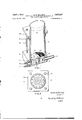
- FIG. 1 is a sectional side view of a casting container and manifold base assembly according to one embodiment of the invention.
- FIG. 2 is a top view of this same embodiment showing the vented weight used to hold the casting material in place against the hydrostatic pressure exerted'by the casting liquid.
- FIG. 3 is a diagrammatic flow sheet illustrating the process of preparing a cast plastic composition in accordance with the invention.
- FIG. 1 illustrates an embodiment of a basal addition casting apparatus constructed according to this invention which comprises a square base equipped with a cupshaped chamber 11.
- a flanged, perforated distributor plate 12 is fitted tightly into the chamber 11 and rests on a flange 13.
- a cylindrical casting container 14 is superimposed in the annular recess formed by the upper portions of the manifold distributor plate and the chamber wall.
- a seal between the casting container 14, distributor plate 12, and chamber 11 is provided by a gasket 15.
- Manifold ducts 16 extend downwardly from the perforations 17 of the distributor plate 12 to within a short distance of the bottom of the chamber 11.
- a casting liquid ber 11 A piece of muslin 22, conforming to the inside diameter of the casting container 14, rests upon the distributor plate 12 and provides a foraminous partition between the contents of the casting container 14 and the entire base assembly.
- the casting container 14 is equipped with a clamping member 23.
- a compression member 24 is fitted around .the casting container 14 and rests upon the clamping member 23.
- Elongated compression studs 25 pass through the compression member 24 and threadedly engage the base 10. When these studs 25 are tightened, the entire apparatus becomes a rigid unit.
- FIG. 2 illustrates a vented weight 39 of substantially thesame diameter as the inside of the cylindrical casting container 34, as it rests upon a-charge of casting powder.
- Toprepare a cast propellant according to one embodir'nent of the invention, a charge of casting material is first prepared by homogeneouslvmixing, in a sweetie barrel .or similar apparatus, granulated, solvent-extruded casting powder .to hold it in place during .the subsequent opera- 1 tion.
- the casting liquid is then slowly admitted through 'the inlet nozzle 18. The initial flow of liquid displaces all air from chamber 11, the air escaping through the outlet it), When casting liquid has completely filled the space within the base assembly and begins to escape through the air outlet 20, the outlet is closed.
- the pressure on the casting liquid system is then raised to the desired point, the liquid is forced upward through the manifold ducts l6 and the foraminous member 22 and is evenly distributed over the cross-sectional area of the base of the casting container 14.
- the liquid rises through the column of casting material displacing all air therein entrapped.
- the flow isshut off at the inlet nozzle 18 and the hose from the casting liquid system is detached.
- the entire unit is stored at elevated temperature for a period necessary to cure and produce a thoroughly con solidated propellant.
- the unit is then removed from storage and cooled.
- the liquid remaining in chamber 11 is then drained off through outlet 21 and the apparatus is disassembled.
- the entire unit may be tipped and the excess "liquid removed through the inlet nozzle 18.
- the container 14 with the propellant therein is removed and the apparatus is then ready to receive a new casting container, such as 14-, to initiate a new casting cycle.
- Example I Six casting units were constructed with casting containers 4 inches in diameter and 12 inches in length. The
- the casting liquid was also evacuated to an absolute pressure of less than 1 cm. for a period of 16 hours.
- the various element of the casting apparatus may be made of any suitable material. It is understood, of course, that the elements contacted by the constituents utilized in the process should withstand detrimental attack thereby.
- the casting containers are preferably made of cellulose acetate, as set forth in the examples, if it is desired to produce a grain with an inhibited outer surface which burns only edgewise and/or internally. However, satisfactory results may be obtained with any nonflammable material of similar nature which has sufficient compatibility with the casting liquid used; so that on curing, a strong bond between powder and container results.
- the propellant may be cast in a container designed to permit removal of the grain after curing. Such container may, therefore, be made of any suit able material which will not adhere to the powder.
- Cast propellants may also be prepared having any desired number and any desired shape of perforations by inserting suitably shaped forms into the casting container prior to charging with the casting material and withdrawing them after curing. These forms should also be made from materials to which the powder will not adhere such as metal, glass and resinous materials.
- the casting containers themselves may be of any desired size or shape and the base assemblies accommodated thereto. Thus, cast propellants of any desired size, perforation and crosssectional configuration, such as cruciform or rosette shapes, may be readily prepared.
- the base assemblies may also be made of a wide range of materials which will not be attacked by the casting liquid or be adversely affected by curing temperatures.
- Example I the entire assembly was made from transparent, high-grade cellulose acetate in order that the progress of the entrained air and the functioning of the air trap feature might be readily observed. Under normal conditions of manufacture, air trap manifold base assemolies made entirely from aluminum have proved highly satisfactory, both from the standpoint of ease of production and performance.
- the foraminous member which is placed over the man ifold distributor plate may be made of any material which will permit liquid flow therethrough and still prevent the powder granules and rate control particles from entering the perforations of the distributor plate. Equaliy satisfactory results have been achieved with various types of cloth and metal screens. Aside from preventing the granules from passing through the perforations of the distributor plate, the foraminous member also assists in distribution of the casting liquid and elimination of channeling. A foraminous member is not necessary if the casting material granules are larger than the perforations in the distributor plate.
- the vented weight illustrated in FIG. 2 may be made of any relatively heavy material which will furnish the necessary pressure to prevent any movement or displacement of the powder granules as the casting liquid courses up through the powder column.
- any clamp or pressure means may be used which is capable of pre- All) 6 venting the movement of the granules of casting material and still allows for ready escape of the displaced air.
- any suitable casting material may be used in this invention.
- the powder granules may be either single or multiple base. Finely divided particles of crystalline explosive may also be added to the powder and evenly distributed therein. If no burning rate control material is present, no particular care need be exercised in charging the powder into the casting container. If burning rate control material is present, the two should be homogeneously mixed in a sweetie barrel, or other mixing means. Preferably, the mixture is then charged by pouring it vertically, and at an even rate, into the casting container. The powder stream should not glance olf the sides of the container or segregation of the denser rate control granules may result. Other suitable charging methods which do not disturb the overall distribution of rate control particles may be used.
- the rate control material may also be charged in evenly spaced strands and the casting powder then added.
- These longitudinally located strands may be retained in any desired position by a number of means.
- a thin cellulose acetate disc may be prepared with perforations to match those of the distributor plate and the ends of the strands may be cemented into other perforations made at the desired intervals.
- Another perforated disc may then be located at the top of the casting container and the strands led through certain per forations located in positions directly above those of the lower disc in which the ends of the strands are cemented.
- the strands are not cemented to the upper perforated disc.
- the lower ends of the strands may be seated in wells drilled between the perforations of the distributor plate.
- the casting powder is evacuated, in a desiccator or other suitable apparatus to an absolute pressure of less than about 1 cm. of mercury for a period of 16 hours to reduce surface moisture.
- the evacuation may be achieved by fitting the casting container with an air-tight cover equipped with a nozzle. This nozzle and the casting liquid inlet nozzle may then be connected to a vacuum line and the entire apparatus evacuated for any desired length of time.
- the casting powder may be packed more compactly in the casting container by such means as tamping the powder or vibrating the container. This operation merely insures a higher ratio of powder to plasticizer, and is in no way vital to the successful operation of the inventron.
- the casting liquid or plasticizer usually employed in preparing propellant grains is desensitized nitroglycerin.
- other liquid explosives or mixtures thereof are also operable.
- the casting liquid is evacuated to an absolute pressure of less than 1 cm. for a period of at least 16 hours before using.
- the casting liquid is preferably admitted to the base assembly under sufficient pressure to give a displacement varying from about 5 to about 10 inches per minute, although rates as high as 20 inches per minute may be used, especially with larger powder granules and less viscous plasticizers.
- the rate at which the casting liquid rises in the casting container will desirably be as great as possible without entrapping air in the powder charge.
- the needed pressure may be obtained by a pressure head created by raising the liquid level of the casting liquid supply several feet above the top of the casting apparatus.
- Various types of pumps or even reduced pressure inside the casting apparatus may also be used to cause the casting liquid to rise through and cover the powder charge. While good results may be obtained with all of these pressure means, the preferred method, especially in the casting of large grains, is to admit the casting liquid into the base assembly under gas pressure.
- an air-tight lid is clamped on the casting liquid container, preferably the same container in which the liquid has been evacuated, and air, nitrogen, or another suitable gas is introduced until the pressure required for satisfactory filling has been obtained. .In the presence of explosive constituents, nitrogen or some other inert gas is preferred.
- the rate of casting liquid addition may be easily controlled by varying the gas pressure within the casting liquid reservoir and the need for a height differential is totally eliminated. In addition, it has been found that satisfactory filling can be accomplished in about one-third less time than with pressure from a hydrostatic head. Extra handling of the casting liquid is also eliminated.
- the casting apparatus must of course be strong enough to withstand the necessary pressure, with an added safety factor, but this presents no problem since propellant grains having a diameter of 12.5 inches and a length of 42 inches have been prepared by use of gas pressures which did not exceed 12 lbs/sq. in. gage.
- a satisfactory gas supply system consists of a highpressure nitrogen cylinder, with standard reducing valves,
- cast propellants Although the preparation of cast propellants is described to illustrate this invention, it is not intended that the invention be confined to the production of cast .propellants.
- the apparatus and process of this invention have equal utility in the preparation of cast plastic compositions generally in which it is desired to produce a cast composition substantially free of'internal and/ or external pitting.
- the cast plastic composition may contain explosive ingredients to produce a propellant, a charge for a gas generating cartridge, a high explosive or the like and the advantages of the invention are pre-' dominant in the art of .cast explosives.
- the apparatus and process of this invention also have utility in the casting of nonexplosive plastic materials such as synthetic resins, particularly transparent or translucent resins, where it is likewise desired to produce a cast composition substantially free of internal and/ or ex- I ternal defects due to air bubbles.
- nonexplosive plastic materials such as synthetic resins, particularly transparent or translucent resins
- the distance the ducts must extend below the manifold distributor plate is governed by the position of the casting liquid inlet port in the base chamber and by the rate of flow of casting liquid .for which the assembl is designed. For a low rate of flow, in which no turbulence occurs within the base, it is only necessary that the lower to travel and thereby provide more time for air bubbles to become disentrained.
- the inlet nozzle is constructed with a bafiie on the inner end to deflect the entering liquid upward.
- the air trap assembly will function equally as well without the baffle, provided the rate of flow is low enough and the nozzle is far enough above the lower extremities of the ducts to eliminate the danger of air bubbles being carried downward and into the duct openings by the downward current of the casting liquid.
- the casting liquid drain port in FIG. 1 provides a means of removing excess liquid from the apparatus prior to disassembly.
- the presence of this drain port is optional since the excess casting liquid may be removed by tipping the apparatus and allowing the liquid to drain out through the inlet nozzle.
- Curing is desirably accomplished by placing the entire casting apparatus, after disconnecting the casting liquid supply line, in a forced air oven at a temperature from about C. to about 80 C. Depending on the type, size, configuration, and perforation of the casting, suitable curing times have been found to vary from as little as 1 to as many as 600 hours.
- the base assembly is removed. If it is found desirable to inhibit either end of the casting as Well as its outer surfaces, a cap or plug, made preferably from the same material as the casting container, may be threaded or otherwise secured to the container. If desired, the seal may be reinforced by means such as a nonfiammable cement or tape.
- the present invention offers important advantages over prior apparatus and processes for producing cast plastic compositions, especially those of larger diameters. All of the safety, efficiency, economy and simplicity of the basal addition method are retained. Moreover,
- the pitting caused by air bubbles entrained in the casting liquid supply is absolutely eliminated by the air trap feature. Further, with the manifold distributor plate of this invention, channeling is also eliminated and an even distribution of casting liquid is achieved across the cross-sectional area of the casting material at the base of the casting container.
- An apparatus for casting plastic compositions by the basal addition method which in combination comprises a base member provided with a chamber, a superimposed perforated manifold distributor plate equipped with mani- 7 fold ducts extending from the perforations of the maniends of the ducts be slightly below the inlet nozzle.
- An apparatus for casting plastic compositions by the basal addition method which in combination comprises a base member provided with a chamber, a superimposed perforated manifold distributor plate equipped with manifold ducts extending from the perforations of the manifold distributor plate to within close proximity of the chamber floor, an annular foraminous member conforming to the upper surface of the manifold distributor plate, a casting liquid inlet located in the chamber Wall at a point above the lower extremities of the manifold ducts, an air outlet located in the chamber wall at a point directly beneath the under surface of the manifold distributor plate and a casting container superimposed with sealirig and supporting means over the manifold distributor p ate.
- An apparatus for casting plastic compositions by the basal addition method which in combination comprises a base member provided with a chamber, a superimposed perforated manifold distributor plate equipped with manifold ductsextendingfrom the perforations of the manifold distributor plate to within close proximity of the chamber floor, an annular foraminous member conforming to the upper surface of the manifold distributor plate, a casting liquid inlet located in the chamber wall at a point above the lower extremities of the manifold ducts, an air outlet located in the chamber wall at a point directly beneath the under surface of the manifold distributor plate, and a casting container superimposed with sealing means over the manifold distributor plate, said container being supported upon the base assembly and sealed thereto by means of a compression member fitted around the container and resting upon a clamping ring, with compression being achieved by elongated studs passing through the compression member and threadedly engaging the base member.
- An apparatus for casting plastic compositions by the basal addition method which in combination comprises a base member provided with a chamber, the Wall of which is flanged near the top, a perforated manifold distributor plate having an annular protrusion near the bottom thereof which rests upon the chamber wall flange forming an annular recess between the upper portions of the manifold distributor plate and the chamber wall, a gasket conforming to the bottom of said recess; the manifold distributor plate being equipped with manifold ducts extending from the perforations thereof to within close proximity of the chamber floor, a casting liquid inlet lo cated in the chamber wall at a point above the lower extremities of the manifold ducts, an air outlet located at a point directly beneath the under surface of the distributor plate, a casting liquid outlet in the chambers bottom, an annular foraminous member superimposed on the distributor plate, a casting container the base of which is seated on the gasket in the annular recess, and a means for supporting the casting container on the base assembly.
- a manifold base assembly for a basal addition casting apparatus comprising in combination a base member provided with a chamber, a perforated manifold distributor plate forming the top of the chamber, said manifold distributor plate having manifold ducts extending from the perforations downward to within close proximity of the chamber bottom, an inlet located in the chamber wall at a point above the lower extremities of the ducts, and an outlet located in the chamber wall directly beneath the under surface of the manifold distributor plate.
- a manifold base assembly for a basal addition casting apparatus comprising in combination a base member provided with a chamber, a perforated manifold distributor plate forming the top of the chamber, said manifold distributor plate having manifold ducts extending from the perforations downward to within close proximity of the chamber bottom, an annular foraminous member conforming to the upper surface of the manifold distributor plate, an inlet nozzle for liquid extending into the chamber located in the chamber wall at a point above the lower extremities of the ducts, said nozzle having an opening in the upper side thereof to direct the entering liquid upward, an outlet for gas located in the chamber wall directly beneath the under surface of the manifold distributor plate, and an outlet for liquid located in the bottom of the chamber.
- An apparatus for casting plastic compositions by the basal addition method which in combination comprises a casting container superimposed on a hollow base member in fluid-impervious relationship therewith, said hollow base member having a plurality of spaced passageways leading from the interior thereof and into the superimposed casting container, an inlet leading into the hollow base member at a point above the beginning of said passageways, and an outlet leading from the hollow base member at a point adjacent the top thereof.
- the process comprising introducing plastic granules into a mold, leading a casting liquid to a delivery point in the mold below the plastic granules, said casting liquid being led along a path containing a confining zone for gas above the liquid level at a point in the path higher than said delivery point to entrap any gaseous medium entrained in the casting liquid, forcing the gas-free casting liquid upwardly from said delivery point through the plastic granules until the granules are covered, and curing said mold and contents to form a consolidated casting.
Landscapes
- Chemical & Material Sciences (AREA)
- Organic Chemistry (AREA)
- Casting Or Compression Moulding Of Plastics Or The Like (AREA)
Description
l -t M April 3, 1962 Filed May 20, 1948 G. W. MGCURDY METHOD AND APPARATUS FOR MANUFAC CAST PLASTIC COMPOSITIONS TURE OF 2 Sheets-Sheet 1 Gordon W McCura y INVENTOR.
WQPM
AGENT.
Apnl 3, 1962 G. w. MCCURDY 3,027,597
METHOD AND APPARATUS FOR MANUFACTURE OF CAST PLASTIC COMPOSITIONS Flled May 20, 1948 2 Sheets-Sheet; 2
CHARGE CASTING CONTAINER WITH PLASTIC POWDER GRANULES EXERT PRESSURE PLASTIC POWDER GRANULES INTRODUCE PRESSURIZED CASTING LIQUID TO MANIFOLD BASE ASSEMBLY FORCE CASTING LIQUID INTO CASTING CONTAINER UNTIL POWDER IS COVERED SUBJECT CASTING CONTAINER AND CONTENTS TO ADVANCED TEMPERATURE TO FORM CAST PROPELLANT FIG.3
GORDON W. McCURDY.
INVENTOR.
BY S 9d; (PM
AGENTI Powder Company, Wilmington, DeL, a corporation of Delaware Filed May 20, 1948, Ser. No. 28,218 12 Claims. (Cl. 18-26) This invention relates to a process and to an apparatus for manufacturing cast compositions, and more particularly to a process and apparatus for the manufacture of cast explosive compositions.
In the manufacture of explosives, smokeless powder propellants suitable for propelling military rockets or actuatingsizable jet devices such as assisted take-ofif motors for airplanes, are normally formed so as to present a relatively small amount of burning surface, and so keep the rate of gas production at the required low level. At first, these propellants did not exceed 4 to 5 inches in diameter and were generally made by the well-known solventless extrusion procedure, which comprises rolling sheets of colloided smokeless power into tight rolls and pressing these rolls through a precision die. This procedure requires specialized and expensive equipment and is intrinsically hazardous due to the high pressures and temperatures involved and the constant danger of fire associated with the rolling process. In addition, the steadily increasing demand for larger propellant grains has made the extrusion method even more undesirable because the larger grains require construction and use of more massive and more expensive equipment.
A much simpler method for fabrication of cast propellants of nearly any size and shape has been developed which essentially comprises the cementing together of smokeless power granules of conventional size and shape by a coating liquid composed of a mixture of nonvolatile explosive and nonexplosive plasticizers. According to this process, the components are introduced into a container of suitable size and shape in increments, the mixture being agitated subsequent to each addition to insure packing and removal of air. The mixture is then cured at an elevated temperature until the plasticizers have been absorbed by the powder granules and the mixture has set in a hard, consolidated mass. This method is intrinsically less hazardous because at no time is the explosive subjected simultaneously to both high pressure and elevated temperature. Furthermore, specialized and expensive equipment is unnecessary.
However, in order to produce a cast propellant which is homogeneous throughout and free from air bubbles or fissures, it is absolutely essential that the casting powder granules, burning rate control particles and plasticizer are uniformly distributed throughout the casting. The method whereby successive increments of the required components are added has not proved satisfactory in this respect since many of the castings were found to contain entrapped air bubbles and/ or local concentrations of nonvolatile plasticizer, casting power, or burning rate control particles. Since these factors cause fluctuation during burning, propellants containing such imperfections give highly unsatisfactory performance.
The tendency to segregation may be substantially eliminated by employing the basal addition casting method disclosed in the co-pending application of D. H. Black, Serial No. 675,436. That method essentially comprises initially mixing the powder components into a homogeneous mass, introducing the mass of powder granules quickly and at an even rate into a suitable casting container, placing a vented weight on top of the powder to hold it in place, and then admitting nonvolatile plasticizers through an opening in the base of the 3,@Z7,597 Patented Apr. 3, 1962 container. Thus, as the casting liquid slowly rises in the container, it forces the air trapped in the powder upward and the casting liquid completely contacts and surrounds the individual powder granules. The casting so produced is homogeneous and completely free from air bubbles which had been trapped in the powder. However, this method still is not completely satisfactory because any air which is trapped in the casting liquid system is forced up into the casting powder at some time after filling commences. The resulting areas of poor consolidation within the cast matrix, caused by the displacement of casting liquid by air bubbles, make part or all of the finished grain unfit for use. Inspection of numerous powder grains made in molds using this method has shown that air carried into the powder matrices by the casting liquid has been one of the foremost causes of poor grain quality. Large numbers of such grains have been found despite the exercise of meticulous care in flushing out casting liquid lines. Furthermore, when grains of large diameter are cast, channeling of the casting liquid occurs because of improper and uneven distribution of the casting liquid over the cross-sectional area of powder at the base of the casting container.
Therefore, it is a principal object of this invention to provide an apparatus and a process for producing hard, homogeneous, well consolidated cast plastic compositions which are completely free of imperfections due to air tarpped either in the casting material or the casting liquid system.
It is also an object of this invention to provide an apparatus employing the basal addition method which will prohibit any entrained air from passing from the casting liquid system into the casting material.
It is a further object of this invention to provide an apparatus employing the basal addition method which will evenly distribute the incoming casting liquid over the cross-sectional area at the base of the casting container and thereby prevent channeling of the casting liquid in the casting material.
Generally described, the present invention comprises a suitable casting container equipped with a manifold base assembly so constructed that all air not displaced from the casting liquid system by the initial flow of casting liquid will be trapped beneath a perforated manifold distributor plate which forms both the top of the manifold base assembly and the bottom of the casting container. A cloth or other foraminous member conforming to the distributor plate is placed between the plate and the contents of the casting container to prevent the casting material from passing through the perforations. Essentially, the trapping of air is accomplished by extending ducts from the holes or perforations in the manifold distributor plate downward to within a short distance of the bottom of the base assembly. The casting liquid inlet to the base assembly is located at a point above the lower extremities of the manifold ducts. An outlet for air or other gaseous substances is provided in the base assembly directly beneath the under surface of the manifold distributor plate and if desired a casting liquid outlet may be provided in the lower portion of the base.
The initial flow of casting liquid displaces the air from the interior of the manifold base assembly, the air escaping through the outlet below the distributor plate. When the casting liquid has completely filled the space within the assembly and begins to escape through the air outlet, this opening is closed. Thereafter the liquid rises through the manifold ducts into the casting material which is disposed in the superimposed casting container. Thus, the casting liquid, since it is introduced above the lower extremities of the manifold ducts, must travel downward to enter the ducts before it can rise into the casting material above. Therefore, any air remaining in the casting liquid system, and which gains entrance to the base assembly at any time after filling has started, rises through the liquid, is positively trapped against the under side of the .manifold plate and is completely prevented from being carried with the casting liquid into the matrix. When sufficient of the casting liquid or plasticizer has been admitted to cover the casting material, the casting liquid inlet is closed and disconnected from the casting liquid system. The entire assembly is then placed in a suitable curing oven, removed and cooled. The resulting cast composition is homogeneous, well consolidated, and is completely free of imperfections caused by air bubbles.
The nature and purpose of the present invention have been indicated in general and there now follows a more detailed description with reference to the accompanying drawings.
7 FIG. 1 is a sectional side view of a casting container and manifold base assembly according to one embodiment of the invention.
FIG. 2 is a top view of this same embodiment showing the vented weight used to hold the casting material in place against the hydrostatic pressure exerted'by the casting liquid.
FIG. 3 is a diagrammatic flow sheet illustrating the process of preparing a cast plastic composition in accordance with the invention.
FIG. 1 illustrates an embodiment of a basal addition casting apparatus constructed according to this invention which comprises a square base equipped with a cupshaped chamber 11. A flanged, perforated distributor plate 12 is fitted tightly into the chamber 11 and rests on a flange 13. A cylindrical casting container 14 is superimposed in the annular recess formed by the upper portions of the manifold distributor plate and the chamber wall. A seal between the casting container 14, distributor plate 12, and chamber 11 is provided by a gasket 15. Manifold ducts 16 extend downwardly from the perforations 17 of the distributor plate 12 to within a short distance of the bottom of the chamber 11. A casting liquid ber 11. A piece of muslin 22, conforming to the inside diameter of the casting container 14, rests upon the distributor plate 12 and provides a foraminous partition between the contents of the casting container 14 and the entire base assembly.
The casting container 14 is equipped with a clamping member 23. A compression member 24 is fitted around .the casting container 14 and rests upon the clamping member 23. Elongated compression studs 25 pass through the compression member 24 and threadedly engage the base 10. When these studs 25 are tightened, the entire apparatus becomes a rigid unit.
FIG. 2 illustrates a vented weight 39 of substantially thesame diameter as the inside of the cylindrical casting container 34, as it rests upon a-charge of casting powder.
Toprepare a cast propellant according to one embodir'nent of the invention, a charge of casting material is first prepared by homogeneouslvmixing, in a sweetie barrel .or similar apparatus, granulated, solvent-extruded casting powder .to hold it in place during .the subsequent opera- 1 tion. The casting liquid is then slowly admitted through 'the inlet nozzle 18. The initial flow of liquid displaces all air from chamber 11, the air escaping through the outlet it), When casting liquid has completely filled the space within the base assembly and begins to escape through the air outlet 20, the outlet is closed. The pressure on the casting liquid system is then raised to the desired point, the liquid is forced upward through the manifold ducts l6 and the foraminous member 22 and is evenly distributed over the cross-sectional area of the base of the casting container 14. The liquid rises through the column of casting material displacing all air therein entrapped. When the casting material is completely covered and the casting liquid begins to exude from the vents of weight 30, the flow isshut off at the inlet nozzle 18 and the hose from the casting liquid system is detached. The entire unit is stored at elevated temperature for a period necessary to cure and produce a thoroughly con solidated propellant. The unit is then removed from storage and cooled. The liquid remaining in chamber 11 .is then drained off through outlet 21 and the apparatus is disassembled. In case a'special casting liquid outlet is not .provided, the entire unit may be tipped and the excess "liquid removed through the inlet nozzle 18. The container 14 with the propellant therein is removed and the apparatus is then ready to receive a new casting container, such as 14-, to initiate a new casting cycle.
In accordance with this invention and to illustrate more particularly the effectiveness of the air trap manifold base assembly, the following examples are given:
Example I Six casting units were constructed with casting containers 4 inches in diameter and 12 inches in length. The
'less than 1 cm. of mercury for a period of 16 hours to reduce surface moisture. The casting liquid was also evacuated to an absolute pressure of less than 1 cm. for a period of 16 hours.
The addition of casting liquid to these units was conducted under controlled conditions such that air was deliberately trapped in the casting liquid supply line at the start of filling; then allowed to be carried with the liquid into the bases of the units after the casting liquid had begun to rise through the casting material. The progress of the entrapped air was observed through the transparent walls of the six units. In all three of the units without the air trap feature, air bubbles entering the base assembly below the manifold plate were observed to rise with the casting liquid, pass through the manifold plate and muslin cloth, into the powder r matrix. These three grains, after curing, were sectioned longitudinally and subjected to X-ray inspection. In all three grains the powder matrices were found to be badly pitted as' a result of the presence of finely dispersed air bubbles. v
In the three casting units equipped with the air trap base assemblies of this invention, all air bubbles entering the base with the casting liquid from'the supply line were observed to rise immediately in the liquid and become trapped against the under side of the manifold distributor plate. Only the liquid was carried through the ducts and into the powder matrices above. After curing, these three grains were sectioned longitudinally and subiected to X-ray examination. The matrices of all three grains were found to be well consolidated and totally free from pits.
' Example II Five casting units with casting containers of 26 inches in diameter had been in use for some time. These units did not contain the air trap base assembly of this invention but were equipped with only the simple manifold bases without the air trap feature. About 80% of the grains produced by this equipment were found to contain badly pitted regions in their lower ends which necessitated scrapping of of their total length. When it was discovered that air entrained in the casting liquid was causing these imperfections, additional precautions were used in flushing out the casting liquid lines. The exercise of meticulous care in purging the system and initially evacuating the liquid resulted in a reduction of the damage, but the amount of scrap directly attributable to air bubbles could not be brought below 5%.
These five casting units were then equipped with the air trap base assemblies of this invention. Since that time no evidence of any pitting due to air bubbles has ever 7 been found.
The various element of the casting apparatus may be made of any suitable material. It is understood, of course, that the elements contacted by the constituents utilized in the process should withstand detrimental attack thereby. The casting containers are preferably made of cellulose acetate, as set forth in the examples, if it is desired to produce a grain with an inhibited outer surface which burns only edgewise and/or internally. However, satisfactory results may be obtained with any nonflammable material of similar nature which has sufficient compatibility with the casting liquid used; so that on curing, a strong bond between powder and container results. Alternatively, the propellant may be cast in a container designed to permit removal of the grain after curing. Such container may, therefore, be made of any suit able material which will not adhere to the powder. Cast propellants may also be prepared having any desired number and any desired shape of perforations by inserting suitably shaped forms into the casting container prior to charging with the casting material and withdrawing them after curing. These forms should also be made from materials to which the powder will not adhere such as metal, glass and resinous materials. The casting containers themselves may be of any desired size or shape and the base assemblies accommodated thereto. Thus, cast propellants of any desired size, perforation and crosssectional configuration, such as cruciform or rosette shapes, may be readily prepared.
The base assemblies may also be made of a wide range of materials which will not be attacked by the casting liquid or be adversely affected by curing temperatures. In Example I the entire assembly was made from transparent, high-grade cellulose acetate in order that the progress of the entrained air and the functioning of the air trap feature might be readily observed. Under normal conditions of manufacture, air trap manifold base assemolies made entirely from aluminum have proved highly satisfactory, both from the standpoint of ease of production and performance.
The foraminous member which is placed over the man ifold distributor plate may be made of any material which will permit liquid flow therethrough and still prevent the powder granules and rate control particles from entering the perforations of the distributor plate. Equaliy satisfactory results have been achieved with various types of cloth and metal screens. Aside from preventing the granules from passing through the perforations of the distributor plate, the foraminous member also assists in distribution of the casting liquid and elimination of channeling. A foraminous member is not necessary if the casting material granules are larger than the perforations in the distributor plate.
The vented weight illustrated in FIG. 2 may be made of any relatively heavy material which will furnish the necessary pressure to prevent any movement or displacement of the powder granules as the casting liquid courses up through the powder column. Alternatively, any clamp or pressure means may be used which is capable of pre- All) 6 venting the movement of the granules of casting material and still allows for ready escape of the displaced air.
Any suitable casting material may be used in this invention. In the manufacture of cast propellants, the powder granules may be either single or multiple base. Finely divided particles of crystalline explosive may also be added to the powder and evenly distributed therein. If no burning rate control material is present, no particular care need be exercised in charging the powder into the casting container. If burning rate control material is present, the two should be homogeneously mixed in a sweetie barrel, or other mixing means. Preferably, the mixture is then charged by pouring it vertically, and at an even rate, into the casting container. The powder stream should not glance olf the sides of the container or segregation of the denser rate control granules may result. Other suitable charging methods which do not disturb the overall distribution of rate control particles may be used. The rate control material may also be charged in evenly spaced strands and the casting powder then added. These longitudinally located strands may be retained in any desired position by a number of means. For instance, a thin cellulose acetate disc may be prepared with perforations to match those of the distributor plate and the ends of the strands may be cemented into other perforations made at the desired intervals. Another perforated disc may then be located at the top of the casting container and the strands led through certain per forations located in positions directly above those of the lower disc in which the ends of the strands are cemented. Preferably, the strands are not cemented to the upper perforated disc. As an alternative, the lower ends of the strands may be seated in wells drilled between the perforations of the distributor plate. Preferably, the casting powder is evacuated, in a desiccator or other suitable apparatus to an absolute pressure of less than about 1 cm. of mercury for a period of 16 hours to reduce surface moisture. The evacuation may be achieved by fitting the casting container with an air-tight cover equipped with a nozzle. This nozzle and the casting liquid inlet nozzle may then be connected to a vacuum line and the entire apparatus evacuated for any desired length of time.
The casting powder may be packed more compactly in the casting container by such means as tamping the powder or vibrating the container. This operation merely insures a higher ratio of powder to plasticizer, and is in no way vital to the successful operation of the inventron.
The casting liquid or plasticizer usually employed in preparing propellant grains is desensitized nitroglycerin. However, other liquid explosives or mixtures thereof are also operable. Preferably, the casting liquid is evacuated to an absolute pressure of less than 1 cm. for a period of at least 16 hours before using. The casting liquid is preferably admitted to the base assembly under sufficient pressure to give a displacement varying from about 5 to about 10 inches per minute, although rates as high as 20 inches per minute may be used, especially with larger powder granules and less viscous plasticizers. The rate at which the casting liquid rises in the casting container will desirably be as great as possible without entrapping air in the powder charge. The needed pressure may be obtained by a pressure head created by raising the liquid level of the casting liquid supply several feet above the top of the casting apparatus. Various types of pumps or even reduced pressure inside the casting apparatus may also be used to cause the casting liquid to rise through and cover the powder charge. While good results may be obtained with all of these pressure means, the preferred method, especially in the casting of large grains, is to admit the casting liquid into the base assembly under gas pressure.
If a hydrostatic head is employed, it is necessary to have a height differential of at least 8 feet between casting liquid and powder to give satisfactory filling of ordinary 7 grains. With some of the larger castings, twice that differential and more has been required. The hazard and inconvenience of elevating a container of high explosive to a height of 8 feet or more are obvious disadvantages of the gravity system. In addition, it has been found that close control of the rate of casting liquid addition is more diificult in the gravity system because of the necessity'of a special screw clamp and flow measuring device. The disadvantage of the reduced pressure system lies in the fact that it tends to draw air into the powder-casting liquid mixture if the slightest leak is encountered. From the safety standpoint, use of liquid pumps with nitroglycerin or similar substances is to be avoided.
These difficulties may be overcome if an air-tight lid is clamped on the casting liquid container, preferably the same container in which the liquid has been evacuated, and air, nitrogen, or another suitable gas is introduced until the pressure required for satisfactory filling has been obtained. .In the presence of explosive constituents, nitrogen or some other inert gas is preferred. The rate of casting liquid addition may be easily controlled by varying the gas pressure within the casting liquid reservoir and the need for a height differential is totally eliminated. In addition, it has been found that satisfactory filling can be accomplished in about one-third less time than with pressure from a hydrostatic head. Extra handling of the casting liquid is also eliminated. The casting apparatus must of course be strong enough to withstand the necessary pressure, with an added safety factor, but this presents no problem since propellant grains having a diameter of 12.5 inches and a length of 42 inches have been prepared by use of gas pressures which did not exceed 12 lbs/sq. in. gage.
A satisfactory gas supply system consists of a highpressure nitrogen cylinder, with standard reducing valves,
connected to an accumulator or surge tank. The latter gree of safety would be suitable.
Although the preparation of cast propellants is described to illustrate this invention, it is not intended that the invention be confined to the production of cast .propellants. The apparatus and process of this invention have equal utility in the preparation of cast plastic compositions generally in which it is desired to produce a cast composition substantially free of'internal and/ or external pitting. The cast plastic composition may contain explosive ingredients to produce a propellant, a charge for a gas generating cartridge, a high explosive or the like and the advantages of the invention are pre-' dominant in the art of .cast explosives. However, the apparatus and process of this invention also have utility in the casting of nonexplosive plastic materials such as synthetic resins, particularly transparent or translucent resins, where it is likewise desired to produce a cast composition substantially free of internal and/ or ex- I ternal defects due to air bubbles.
It will be seen, therefore, thatthis invention may be carried out'by the use of various modifications and changes without departing from its spirit and scope. V
The distance the ducts must extend below the manifold distributor plate is governed by the position of the casting liquid inlet port in the base chamber and by the rate of flow of casting liquid .for which the assembl is designed. For a low rate of flow, in which no turbulence occurs within the base, it is only necessary that the lower to travel and thereby provide more time for air bubbles to become disentrained.
It will be noted that in FIG. 1, the inlet nozzle is constructed with a bafiie on the inner end to deflect the entering liquid upward. The air trap assembly will function equally as well without the baffle, provided the rate of flow is low enough and the nozzle is far enough above the lower extremities of the ducts to eliminate the danger of air bubbles being carried downward and into the duct openings by the downward current of the casting liquid.
The casting liquid drain port in FIG. 1 provides a means of removing excess liquid from the apparatus prior to disassembly. The presence of this drain port is optional since the excess casting liquid may be removed by tipping the apparatus and allowing the liquid to drain out through the inlet nozzle.
Curing is desirably accomplished by placing the entire casting apparatus, after disconnecting the casting liquid supply line, in a forced air oven at a temperature from about C. to about 80 C. Depending on the type, size, configuration, and perforation of the casting, suitable curing times have been found to vary from as little as 1 to as many as 600 hours. When the desired curing has been accomplished, the base assembly is removed. If it is found desirable to inhibit either end of the casting as Well as its outer surfaces, a cap or plug, made preferably from the same material as the casting container, may be threaded or otherwise secured to the container. If desired, the seal may be reinforced by means such as a nonfiammable cement or tape.
The present invention, therefore, offers important advantages over prior apparatus and processes for producing cast plastic compositions, especially those of larger diameters. All of the safety, efficiency, economy and simplicity of the basal addition method are retained. Moreover,
-with the present invention the pitting caused by air bubbles entrained in the casting liquid supply is absolutely eliminated by the air trap feature. Further, with the manifold distributor plate of this invention, channeling is also eliminated and an even distribution of casting liquid is achieved across the cross-sectional area of the casting material at the base of the casting container.
What I claim and desire to protect by Letters Patent is:
1. An apparatus for casting plastic compositions by the basal addition method which in combination comprises a base member provided with a chamber, a superimposed perforated manifold distributor plate equipped with mani- 7 fold ducts extending from the perforations of the maniends of the ducts be slightly below the inlet nozzle. For
higher rates of flow, in which muchturbulence occurs, it is necessary that the ducts extend 'further below the inlet nozzle-to allow .a greater downward distancc for theliquid 2. An apparatus for casting plastic compositions by the basal addition method which in combination comprises a base member provided with a chamber, a superimposed perforated manifold distributor plate equipped with manifold ducts extending from the perforations of the manifold distributor plate to within close proximity of the chamber floor, an annular foraminous member conforming to the upper surface of the manifold distributor plate, a casting liquid inlet located in the chamber Wall at a point above the lower extremities of the manifold ducts, an air outlet located in the chamber wall at a point directly beneath the under surface of the manifold distributor plate and a casting container superimposed with sealirig and supporting means over the manifold distributor p ate.
3. An apparatus for casting plastic compositions by the basal addition method which in combination comprises a base member provided with a chamber, a superimposed perforated manifold distributor plate equipped with manifold ductsextendingfrom the perforations of the manifold distributor plate to within close proximity of the chamber floor, an annular foraminous member conforming to the upper surface of the manifold distributor plate, a casting liquid inlet located in the chamber wall at a point above the lower extremities of the manifold ducts, an air outlet located in the chamber wall at a point directly beneath the under surface of the manifold distributor plate, and a casting container superimposed with sealing means over the manifold distributor plate, said container being supported upon the base assembly and sealed thereto by means of a compression member fitted around the container and resting upon a clamping ring, with compression being achieved by elongated studs passing through the compression member and threadedly engaging the base member.
4. An apparatus for casting plastic compositions by the basal addition method which in combination comprises a base member provided with a chamber, the Wall of which is flanged near the top, a perforated manifold distributor plate having an annular protrusion near the bottom thereof which rests upon the chamber wall flange forming an annular recess between the upper portions of the manifold distributor plate and the chamber wall, a gasket conforming to the bottom of said recess; the manifold distributor plate being equipped with manifold ducts extending from the perforations thereof to within close proximity of the chamber floor, a casting liquid inlet lo cated in the chamber wall at a point above the lower extremities of the manifold ducts, an air outlet located at a point directly beneath the under surface of the distributor plate, a casting liquid outlet in the chambers bottom, an annular foraminous member superimposed on the distributor plate, a casting container the base of which is seated on the gasket in the annular recess, and a means for supporting the casting container on the base assembly.
5. A manifold base assembly for a basal addition casting apparatus comprising in combination a base member provided with a chamber, a perforated manifold distributor plate forming the top of the chamber, said manifold distributor plate having manifold ducts extending from the perforations downward to within close proximity of the chamber bottom, an inlet located in the chamber wall at a point above the lower extremities of the ducts, and an outlet located in the chamber wall directly beneath the under surface of the manifold distributor plate.
6. A manifold base assembly for a basal addition casting apparatus comprising in combination a base member provided with a chamber, a perforated manifold distributor plate forming the top of the chamber, said manifold distributor plate having manifold ducts extending from the perforations downward to within close proximity of the chamber bottom, an annular foraminous member conforming to the upper surface of the manifold distributor plate, an inlet nozzle for liquid extending into the chamber located in the chamber wall at a point above the lower extremities of the ducts, said nozzle having an opening in the upper side thereof to direct the entering liquid upward, an outlet for gas located in the chamber wall directly beneath the under surface of the manifold distributor plate, and an outlet for liquid located in the bottom of the chamber.
7. An apparatus for casting plastic compositions by the basal addition method which in combination comprises a casting container superimposed on a hollow base member in fluid-impervious relationship therewith, said hollow base member having a plurality of spaced passageways leading from the interior thereof and into the superimposed casting container, an inlet leading into the hollow base member at a point above the beginning of said passageways, and an outlet leading from the hollow base member at a point adjacent the top thereof.
8. In the manufacture of castings of plastic compositions the process comprising introducing plastic granules into a mold, leading a casting liquid to a delivery point in the mold below the plastic granules, said casting liquid being led along a path containing a confining zone for gas above the liquid level at a point in the path higher than said delivery point to entrap any gaseous medium entrained in the casting liquid, and forcing the gas-free casting liquid upwardly from said delivery point through the plastic granules.
9. In the manufacture of castings of plastic compositions the process comprising introducing plastic granules into a mold, leading a casting liquid to a delivery point in the mold below the plastic granules, said casting liquid being led along a path containing a confining zone for gas above the liquid level at a point in the path higher than said delivery point to entrap any gaseous medium entrained in the casting liquid, forcing the gas-free casting liquid upwardly from said delivery point through the plastic granules until the granules are covered, and curing said mold and contents to form a consolidated casting.
10. The process according to claim 9 in which the plastic granules are grains of smokeless powder.
11. In the manufacture of cast smokeless powder propellants the process comprising introducing grains of smokeless powder into a mold, leading a casting liquid containing a liquid explosive nitric ester to a delivery point in the mold below the plastic granules, said casting liquid being led along a path containing a confining zone for gas above the liquid level at a point in the path higher than said delivery point to entrap any gaseous medium entrained in the casting liquid, forcing the gas-free casting liquid upwardly from said delivery point through the plastic granules until the granules are covered, and curing said mold and contents to form a consolidated casting.
12. The process according to claim 11 in which the mold and contents are cured at a temperature of from 30-80 C. to form a consolidated casting.
References Cited in the file of this patent UNITED STATES PATENTS 435,842 Lamm Sept. 2, 1890 753,959 Crump Mar. 8, 1904 1,878,870 Linder Sept. 20, 1932 2,085,959 Donnegan July 6, 1937 2,283,688 Mergier et al May 19, 1942 2,335,371 Willis Nov. 30, 1943 2,347,320 Hiltner Apr. 25, 1944 2,437,694 Hickman Mar. 16, 1948
Priority Applications (1)
| Application Number | Priority Date | Filing Date | Title |
|---|---|---|---|
| US28218A US3027597A (en) | 1948-05-20 | 1948-05-20 | Method and apparatus for manufacture of cast plastic compositions |
Applications Claiming Priority (1)
| Application Number | Priority Date | Filing Date | Title |
|---|---|---|---|
| US28218A US3027597A (en) | 1948-05-20 | 1948-05-20 | Method and apparatus for manufacture of cast plastic compositions |
Publications (1)
| Publication Number | Publication Date |
|---|---|
| US3027597A true US3027597A (en) | 1962-04-03 |
Family
ID=21842200
Family Applications (1)
| Application Number | Title | Priority Date | Filing Date |
|---|---|---|---|
| US28218A Expired - Lifetime US3027597A (en) | 1948-05-20 | 1948-05-20 | Method and apparatus for manufacture of cast plastic compositions |
Country Status (1)
| Country | Link |
|---|---|
| US (1) | US3027597A (en) |
Cited By (13)
| Publication number | Priority date | Publication date | Assignee | Title |
|---|---|---|---|---|
| US3212256A (en) * | 1961-10-24 | 1965-10-19 | Henry T Sampson | Case bonding system for cast composite propellants |
| US3222433A (en) * | 1961-07-18 | 1965-12-07 | Jr Nicolas Makay | Method of casting propellant within a rocket motor casing |
| US3252369A (en) * | 1964-02-18 | 1966-05-24 | Charles E Bartley | Method and apparatus for loading solid propellant into rocket casings and the like |
| US3263275A (en) * | 1963-07-22 | 1966-08-02 | Thiokol Chemical Corp | Apparatus for casting small solid propellant rocket motors for testing purposes |
| US3317641A (en) * | 1964-03-11 | 1967-05-02 | Wilbur C Heier | Method for molding compounds |
| US3419644A (en) * | 1966-01-21 | 1968-12-31 | Bofors Ab | Method of filling a tubular part with a solid, granular substance and a liquid substance |
| US3427368A (en) * | 1967-05-15 | 1969-02-11 | United Aircraft Corp | Process for forming a gel within a container |
| US3470273A (en) * | 1966-06-10 | 1969-09-30 | Imp Metal Ind Kynoch Ltd | Top casting under pressure of rocket motor propellants |
| US3734982A (en) * | 1962-02-02 | 1973-05-22 | Us Navy | Process for case bonding cast composite propellant grains |
| FR2577548A1 (en) * | 1985-02-14 | 1986-08-22 | Poudres & Explosifs Ste Nale | PROCESS AND PLANT FOR THE PRODUCTION OF PROPERGOL BLOCKS BY THE MOLDING METHOD |
| US20080040895A1 (en) * | 2004-11-16 | 2008-02-21 | Rafael - Armament Development Authority Ltd. | Highly-Filled, High-Viscosity Paste Charge, And Method And Device For Production Thereof |
| US20100180757A1 (en) * | 2009-01-19 | 2010-07-22 | Agency For Defense Development | Method and apparatus for loading cartridges with pressable plastic bonded explosives |
| US20210347095A1 (en) * | 2020-03-16 | 2021-11-11 | Beijing Institute Of Technology | Device and method for controlling transverse and longitudinal stress waves during curing process of energetic composite materials |
Citations (8)
| Publication number | Priority date | Publication date | Assignee | Title |
|---|---|---|---|---|
| US435842A (en) * | 1890-09-02 | Manufacturing explosive charges | ||
| US753959A (en) * | 1903-06-27 | 1904-03-08 | Samuel Crump | Method of making printers' rollers. |
| US1878870A (en) * | 1927-04-09 | 1932-09-20 | Pittsburgh Plate Glass Co | Method of making alpha refractory cast article |
| US2085959A (en) * | 1935-07-15 | 1937-07-06 | Daniel H Donegan | Apparatus for casting printers' rollers |
| US2283688A (en) * | 1937-12-20 | 1942-05-19 | Mergier Paul Louis | Process for molding colloidal matters |
| US2335371A (en) * | 1939-05-09 | 1943-11-30 | Sanford L Willis | Method of molding plastic material |
| US2347320A (en) * | 1940-06-27 | 1944-04-25 | Rohm & Haas | Casting composition |
| US2437694A (en) * | 1946-05-15 | 1948-03-16 | Nasa | Method for blending powder grains |
-
1948
- 1948-05-20 US US28218A patent/US3027597A/en not_active Expired - Lifetime
Patent Citations (8)
| Publication number | Priority date | Publication date | Assignee | Title |
|---|---|---|---|---|
| US435842A (en) * | 1890-09-02 | Manufacturing explosive charges | ||
| US753959A (en) * | 1903-06-27 | 1904-03-08 | Samuel Crump | Method of making printers' rollers. |
| US1878870A (en) * | 1927-04-09 | 1932-09-20 | Pittsburgh Plate Glass Co | Method of making alpha refractory cast article |
| US2085959A (en) * | 1935-07-15 | 1937-07-06 | Daniel H Donegan | Apparatus for casting printers' rollers |
| US2283688A (en) * | 1937-12-20 | 1942-05-19 | Mergier Paul Louis | Process for molding colloidal matters |
| US2335371A (en) * | 1939-05-09 | 1943-11-30 | Sanford L Willis | Method of molding plastic material |
| US2347320A (en) * | 1940-06-27 | 1944-04-25 | Rohm & Haas | Casting composition |
| US2437694A (en) * | 1946-05-15 | 1948-03-16 | Nasa | Method for blending powder grains |
Cited By (21)
| Publication number | Priority date | Publication date | Assignee | Title |
|---|---|---|---|---|
| US3222433A (en) * | 1961-07-18 | 1965-12-07 | Jr Nicolas Makay | Method of casting propellant within a rocket motor casing |
| US3212256A (en) * | 1961-10-24 | 1965-10-19 | Henry T Sampson | Case bonding system for cast composite propellants |
| US3734982A (en) * | 1962-02-02 | 1973-05-22 | Us Navy | Process for case bonding cast composite propellant grains |
| US3263275A (en) * | 1963-07-22 | 1966-08-02 | Thiokol Chemical Corp | Apparatus for casting small solid propellant rocket motors for testing purposes |
| US3252369A (en) * | 1964-02-18 | 1966-05-24 | Charles E Bartley | Method and apparatus for loading solid propellant into rocket casings and the like |
| US3317641A (en) * | 1964-03-11 | 1967-05-02 | Wilbur C Heier | Method for molding compounds |
| US3419644A (en) * | 1966-01-21 | 1968-12-31 | Bofors Ab | Method of filling a tubular part with a solid, granular substance and a liquid substance |
| US3486330A (en) * | 1966-01-21 | 1969-12-30 | Bofors Ab | Encased propellant for a rocket motor |
| US3470273A (en) * | 1966-06-10 | 1969-09-30 | Imp Metal Ind Kynoch Ltd | Top casting under pressure of rocket motor propellants |
| US3427368A (en) * | 1967-05-15 | 1969-02-11 | United Aircraft Corp | Process for forming a gel within a container |
| FR2577548A1 (en) * | 1985-02-14 | 1986-08-22 | Poudres & Explosifs Ste Nale | PROCESS AND PLANT FOR THE PRODUCTION OF PROPERGOL BLOCKS BY THE MOLDING METHOD |
| EP0192566A1 (en) * | 1985-02-14 | 1986-08-27 | Societe Nationale Des Poudres Et Explosifs | Process and device for ensuring the transfer of a fluid containing an explosive component |
| US20080040895A1 (en) * | 2004-11-16 | 2008-02-21 | Rafael - Armament Development Authority Ltd. | Highly-Filled, High-Viscosity Paste Charge, And Method And Device For Production Thereof |
| US20100288404A1 (en) * | 2004-11-16 | 2010-11-18 | Rafael Advanced Defense Systems Ltd. | Highly-Filled, High-Viscosity Paste Charge, And Method And Device For Production Thereof |
| US7938637B2 (en) * | 2004-11-16 | 2011-05-10 | Rafael Advanced Defense Systems Ltd. | Highly-filled, high-viscosity paste charge, and method and device for production thereof |
| US20110209600A1 (en) * | 2004-11-16 | 2011-09-01 | Rafael Advanced Defense Systems Ltd. | Highly-Filled, High-Viscosity Paste Charge, And Method And Device For Production Thereof |
| US20110209805A1 (en) * | 2004-11-16 | 2011-09-01 | Rafael Advanced Defense Systems Ltd. | Highly-Filled, High-Viscosity Paste Charge, And Method And Device For Production Thereof |
| US8309001B2 (en) | 2004-11-16 | 2012-11-13 | Rafael Advanced Defence Systems Ltd | Method of de-aerating a high-viscosity paste charge |
| US20100180757A1 (en) * | 2009-01-19 | 2010-07-22 | Agency For Defense Development | Method and apparatus for loading cartridges with pressable plastic bonded explosives |
| US20210347095A1 (en) * | 2020-03-16 | 2021-11-11 | Beijing Institute Of Technology | Device and method for controlling transverse and longitudinal stress waves during curing process of energetic composite materials |
| US11745396B2 (en) * | 2020-03-16 | 2023-09-05 | Beijing Institute Of Technology | Device and method for controlling transverse and longitudinal stress waves during curing process of energetic composite materials |
Similar Documents
| Publication | Publication Date | Title |
|---|---|---|
| US3027597A (en) | Method and apparatus for manufacture of cast plastic compositions | |
| US2437694A (en) | Method for blending powder grains | |
| US2129240A (en) | Method and apparatus for molding articles | |
| US2825107A (en) | Method of making hollow sand cores for metal casting | |
| US3562364A (en) | Remote propellant casting process | |
| US3205286A (en) | Smokeless powder manufacture | |
| US2784638A (en) | Apparatus for and method of loading fusible explosive materials into shell casings and the like | |
| US3379796A (en) | Casting propellant charges | |
| US2259465A (en) | Apparatus for consolidating metal powders | |
| US8309001B2 (en) | Method of de-aerating a high-viscosity paste charge | |
| US3028274A (en) | Extrusion method for manufacturing smokeless powder | |
| US3010354A (en) | Rocket grain and method for restricting same | |
| US4393014A (en) | Method of casting explosive charge with high solids content | |
| US3600486A (en) | Pressure casting process | |
| KR940003249B1 (en) | Injection operation method of fluid containing explosive component and device therefor | |
| US2479727A (en) | Elimination of fissures with carbon dioxide | |
| Steinberger et al. | Manufacture of cast double-base propellant | |
| US3274651A (en) | Method for injecting sand in moulding machines | |
| US3107574A (en) | System for deaeration and casting of elastomer bonded propellants | |
| GB1502877A (en) | Method of producing vacuum in a receptacle and a vacuum pump for effecting same | |
| US2935762A (en) | Production of molded sponge plastic | |
| US3082659A (en) | Loading device | |
| US3223756A (en) | Smokeless powder manufacture | |
| US925419A (en) | Process of increasing the density of fusible explosive nitro substances. | |
| US4068703A (en) | Apparatus for catalytic gassing in the manufacture of foundry cores and molds |