US2937515A - Warp jacquard knitting machine - Google Patents
Warp jacquard knitting machine Download PDFInfo
- Publication number
- US2937515A US2937515A US689004A US68900457A US2937515A US 2937515 A US2937515 A US 2937515A US 689004 A US689004 A US 689004A US 68900457 A US68900457 A US 68900457A US 2937515 A US2937515 A US 2937515A
- Authority
- US
- United States
- Prior art keywords
- machine
- warp
- bar
- needles
- guides
- Prior art date
- Legal status (The legal status is an assumption and is not a legal conclusion. Google has not performed a legal analysis and makes no representation as to the accuracy of the status listed.)
- Expired - Lifetime
Links
Images


Classifications
-
- D—TEXTILES; PAPER
- D04—BRAIDING; LACE-MAKING; KNITTING; TRIMMINGS; NON-WOVEN FABRICS
- D04B—KNITTING
- D04B23/00—Flat warp knitting machines
- D04B23/22—Flat warp knitting machines with special thread-guiding means
-
- D—TEXTILES; PAPER
- D04—BRAIDING; LACE-MAKING; KNITTING; TRIMMINGS; NON-WOVEN FABRICS
- D04B—KNITTING
- D04B27/00—Details of, or auxiliary devices incorporated in, warp knitting machines, restricted to machines of this kind
- D04B27/10—Devices for supplying, feeding, or guiding threads to needles
- D04B27/24—Thread guide bar assemblies
- D04B27/32—Thread guide bar assemblies with independently-movable thread guides controlled by Jacquard mechanisms
Definitions
- WARP JACQUARD KNITTING MACHINE Filed Oct. 8, 1957 7 Sheets-Sheet 6 EJ ELlA ET AL WARP JACQUARD KNITTING MACHINE 7 Sheets-Sheet 7 Filed Oct. 8, 1957 m m w. I V Wa /fil al 1 k Un tat Pa 77 f 2,937,515 V V WARP JACQUARD MACHINE Ezio Elia, Ibis, Via Valeggio, Turin, Italy, and Albino Bracco, 7, Via S. Rocco, Molteno (Como), Italy Filed Oct. 8, 1957, Ser. No. 689,094 Claims priority, application Italy Oct. 8,1956; 2 Claims. 01. sa -s j This invention relates to a weft insertion mechanism employing hooked needles. 1
- the main feature of the mechanism resides inthe fact that the weft thread-guides perform vertical and transverse movements with respect to the knitting machine front, synchronously with the longitudinal movement of the needles, with the swinging and translational movement of the warp thread guides and a cross bar adapted to close the needle books.
- the vertical movement of the ternately perform a free vertical movement to form the ground lattice interlacing of the fabric and a vertical movement controlled by the perforated cards of the At front of the needle bed 1 and cross bar 4 a cylindrical bar 6 is arranged which performs a swinging motion about its axis, and a longitudinal and transverse displacement as explained hereafter.
- Figure 3 shows part of the left-hand side ofthe machine, limited to the machine parts involved by the invention
- Figure 4 is a cross sectional view of the machine
- Figure 5 is a diagrammatical sectional view on an enlarged scale of the machine region at which the fabric is formed, during a first step of the process;
- Figure 6 is a diagrammatical sectional view on line VI'VI of Figure 5;
- Figure 7 is a diagrammatical view of the machine at a subsequent step of the process
- Figure 8 is a sectional view online VIII-VIII of Figure 7;
- Figure 10 is a diagrammatical front view of Figure 5.
- Ide notes a needle bedwhich is fixed to the'frame of the Imachinesextending along'th'e front thereof and is provided at its top with a plurality of teeth extending 6 the warp thread extends.
- the rods 7 act as warp threadguides and are arranged substantially in a longitudinal direction at the clearances between the needles 2.
- A' further bar 9, parallel with the abovementioned bar 6, is mounted for oscillationabout its axis and carries by means of two arms 10 a bar ll-adapted to press on the hooks Zn on theneedles to close them.
- the bar 11 is substantially rectangular in cross section and is arranged in front of the region at which the fabric is formed above the warp thread-guides 7.
- a beam 12 is arranged extending along the front of themachine and formed with a set of forward and rearvnotches in which two sets of substantially vertical rods 13, 14 are guided.
- the rods 13, 14 carry at their lower end sleeves 15, 16, respectively, serving as weft thread guides.
- the thread guides aresituated right in front at the notches in the needle bed 1 guiding the needles.
- the rods 13, 14 carrying the weft thread-guides are articulated at their top ends to levers 17, 19, respec tively, swinging about pivots 18, 20, respectively.
- the levers 17, 19 are connected at their end remote from the pivots to substantially vertical wires 21, 22 which are guided in a top support 23 and about a mechanism 24 comprising a perforated card 25 known as Jacquard.
- the weft thread-guides15, 16 are arranged at the clearances between the needles 2, hence approximately.
- the needles 2 are lifted, the needles 2 being withdrawn, the warp thread' guides 7 in their lowered position, the pressure bar.11 in its raisedposition andthe beam moved to the right.
- the beam performs a downward. stroke fast with the weft thread-guides 15, 16.
- the needles 2 perform a forward movement and the weft thread-guides 7 are raised, displaced to the right and subsequently lowered, causing the weft threads to engage the hooks 2a on the needles.
- the pressure bar 11 sinks down coming into contact with the needle hooks and causing them to close.
- the beam 12 and weft threadguides 15, 16 are then lifted, theneedles 2 moving backwards causing the knots to form on the warp threads.
- the pressure bar 11 then swings upwardly, the beam moving to the left.
- the perforated card Jacquard mechanism performs a selection among the threads 21, 22 by means ofone card and admits of part only of the weft thread guides to be lowered, the others remaining in their raised position.
- the needles 2 move forward causing the selected weft threads to interlace with their corresponding warp threads;
- the warp threadguides 7 swing upwardly (see Fig. 9.), subsequently v er.'-
- the pressure bar 11 is subsequently lowered to cause the needle hooks to close, whereupon the needles move 2,937,515 Patented May 24, 196i)
- the warp thread guides 7 perform together with the carrier bar 6 a movement towards and away from the needles, combined with the needle movement itself.
- Figures 1 to 4 show they general configuration of the machine and the diagrammatical arrangement of the controls of the above described constituents.
- the beam 12 carries at its ends two extensions 26 guided for displacement along the axis of the beam with respect to shoes 27 which are in turn vertically slidable with respect to supports 28 fixed to the frame of the machine. 7
- An electric motor 30 drives through speed reducing belt gearings 31, 32 and a friction clutch 33 controlled by a control lever 34 a primary shaft 35 arranged on the right-hand side of the machine.
- the shaft 35 drives through gears 36, 37 and 38 a lower shaft 39 driving in turn through a pair of conical toothed wheels 40 a shaft 41 arranged on the front lower portion of the machine.
- the main shaft 35 drives through a pair of conical toothed wheels 42 a shaft 43 arranged at the rear of the machine.
- Cams 44 are arranged on the shaft 43 to longitudinally move rods 45 connected to the needle carrier 3.
- the same shaft 43 has mounted thereon cams 46 by which arms 47 are oscillated about pivots 48.
- the arms 47 are connected by links 49 to levers 50 oscillating in turn about the axis of a bar 51. Oscillation of the bar 51 is transmitted over an arm 52 arranged on the left: hand side of the machine to a leverage comprising a link 53 and an arm 54, the latter being keyed to the bar 6 carrying the warp thread guides 7.
- the bar 6 carrying the warp thread guides moreover performs movements towards and away from the needles caused by bell crank arms 56 oscillating about a bar 57 and actuated by earns 58 mounted on the shaft 41.
- the same shaft 41 has further keyed thereto cams 59 which oscillate through arms 60 the bar 9 carrying arms and pressure bar 11.
- the endwise movementof the bar 6 carrying the warp thread guides is effected by a face cam 61 mounted on the primary shaft 35 acting on the bar 6 (- Figure 2).
- the movement of the beam along its axis is effected by a cam 62 mounted on the shaft 39 ( Figure 2).
- the cam 62 drives a rocking lever 63 which oscillates about a pivot 64 and has a button 65 thereon engaged in a slot 66 in one of the extensions 26 on the beam.
- the upward and downward movement of the beam is effected by cams 67 keyed to the shaft 43 which oscillate rocking levers 68 about pivots 69.
- the two rocking levers 68 arranged at the head portions of the machine directly act on adjustable push members 70 secured to the shoes 27.
- the primary shaft 35 is provided at its front with a handwheel 71 for hand operation of the machine during the initial phase setting.
- the figures further show diagrammatically the lower drums 72 and 73 guiding the formed fabric and the rear collecting roller 74.
- Figure 1a further shows spools 75 from which the warp threads unwind.
- the control of the perforated card Jacquard mechanism is effected through leverages 76, 78 and 79, 81 oscillating about pivots 77, 80, respectively.
- the vertical pull rods 78 and 81 of the said leverages are actuated by a cam 82 and a crank 83, respectively, which are driven from the primary shaft 35.
- the above described machine permits of effecting an initial setting of its constituents in a much more rapid manner than machines known heretofore. Moreover, it affords a high number of pattern combinations inasmuch as the formation of the combinations of the partners is governed by the perforated cards.
- the machine further permits of manufacturing fabrics of any desired degree of fineness and with two superposed patterns which are determined by the sets of weft thread guides 15, 16. d r H
- the machine further permits of manufacturing fabrics of any desired degree of fineness and with two superposed patterns which are determined by the sets of weft thread guides 15, 16. d r H
- a machine for manufacturing knitted fabrics of the type comprising a stationary needle bed having therein hooked needles movable inward and outward of the bed, means for laying warped yarns in the hooks, means for engaging weft yarns in said hooks, a jacquard for controlling the operation of said weft yarn engaging means, and a guide beam for cooperating with said needle bed, said beam extending along the front of said machine parallel to said bed and being mounted in said frame movable alternatively in a direction perpendicular to the needles path and in a direction along said needle bed, means for controlling the movement of said beam and for synchronizing it with the movement of the needles, a first and secured row of weft yarn guides carried by.
- each guide being mounted in said beam individually displaceable with respect of said beam in a direction sub: stantially perpendicular to that of the movement of said needles, means being provided for selectively controlling said displacement of said weft yarn guides by the jacquard during the movement of said beam, whereby said guides pass the weft yarn below one or more needles before each outward movement of the latter.
- weft yarn guides have the form of sleeves secured to rods adjacent to one of opposite lateral face of said beam, each rod being hinged to a lever rockingly supported at the upper end of said beam and having their free ends connected by means of wires to the jacquard arranged above the needle bed and displacement rearwardly with respect to the latter.
Landscapes
- Engineering & Computer Science (AREA)
- Textile Engineering (AREA)
- Knitting Machines (AREA)
Description
May 24,1960
Filed Oct. 8. 1957 E. ELIA ET AL WARP JACQUARD KNITTING MACHINE Fig. 7
7 Sheets-Sheet 1 'Ma 24, 1960 E. ELIA ET AL 2,937,515
WARP JACQUARD KNITTING MACHINE Filed Oct. 8, 1957 7 Sheets-Sheet 2 Fig. 7a
E ELIA ET AL WARP JACQUARD KNITTING MACHINE May 24, 1960 mm Oct 8, 1957 III May 24, 1960 E. ELIA ET AL 2,937,515
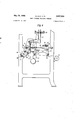
WARP JACQUARD KNITTING MACHINE Filed Oct. 8, 1957 7 Sheets-Sheet 4 Fig. 3
7 I L I a3 68 69 H 26 W 6 May 24, 1960 Filed Oct. 8, 1957 E. ELIA ETA Fig. 4
7 Sheets-Sheet 5 May 24, 1960 E. ELIA ET AL 2,937,515
WARP JACQUARD KNITTING MACHINE Filed Oct. 8, 1957 7 Sheets-Sheet 6 EJ ELlA ET AL WARP JACQUARD KNITTING MACHINE 7 Sheets-Sheet 7 Filed Oct. 8, 1957 m m w. I V Wa /fil al 1 k Un tat Pa 77 f 2,937,515 V V WARP JACQUARD MACHINE Ezio Elia, Ibis, Via Valeggio, Turin, Italy, and Albino Bracco, 7, Via S. Rocco, Molteno (Como), Italy Filed Oct. 8, 1957, Ser. No. 689,094 Claims priority, application Italy Oct. 8,1956; 2 Claims. 01. sa -s j This invention relates to a weft insertion mechanism employing hooked needles. 1
The main feature of the mechanism resides inthe fact that the weft thread-guides perform vertical and transverse movements with respect to the knitting machine front, synchronously with the longitudinal movement of the needles, with the swinging and translational movement of the warp thread guides and a cross bar adapted to close the needle books. The vertical movement of the ternately perform a free vertical movement to form the ground lattice interlacing of the fabric and a vertical movement controlled by the perforated cards of the At front of the needle bed 1 and cross bar 4 a cylindrical bar 6 is arranged which performs a swinging motion about its axis, and a longitudinal and transverse displacement as explained hereafter. l
, Said bar 6 has secured thereto a plurality of rods 7 g each formed at its lowerend with a hole 8 through which Jacquard mechanism to form an interlacing correspond ing to the pattern. I e Further characteristic features and advantages of this invention will be understood from the detailed appended description referring to the accompanying drawings, which diagrammatically show byway of a non-limiting example an embodiment thereof. t Figures 1 and la show diagrammatically a longitudinal sectional view and a front view of the machine, respectively; Figure 2 diagrammatically shows the right-hand side of the machine;
Figure 3 shows part of the left-hand side ofthe machine, limited to the machine parts involved by the invention;
Figure 4 is a cross sectional view of the machine;
Figure 5 is a diagrammatical sectional view on an enlarged scale of the machine region at which the fabric is formed, during a first step of the process;
Figure 6 is a diagrammatical sectional view on line VI'VI of Figure 5;
Figure 7 is a diagrammatical view of the machine at a subsequent step of the process;
Figure 8 is a sectional view online VIII-VIII of Figure 7;
Figure 9 is adiagrammatical' view ofthe machine at a further subsequent step; v
Figure 10 is a diagrammatical front view of Figure 5. Referring first to Figures 5 to 10 showing the corrstituents of the machine directly adapted to form the fabric, Idenotes a needle bedwhich is fixed to the'frame of the Imachinesextending along'th'e front thereof and is provided at its top with a plurality of teeth extending 6 the warp thread extends.- The rods 7 act as warp threadguides and are arranged substantially in a longitudinal direction at the clearances between the needles 2.
A' further bar 9, parallel with the abovementioned bar 6, is mounted for oscillationabout its axis and carries by means of two arms 10 a bar ll-adapted to press on the hooks Zn on theneedles to close them.
The bar 11 is substantially rectangular in cross section and is arranged in front of the region at which the fabric is formed above the warp thread-guides 7.
, 'Above the needle bed 1 a beam 12 is arranged extending along the front of themachine and formed with a set of forward and rearvnotches in which two sets of substantially vertical rods 13, 14 are guided. The rods 13, 14 carry at their lower end sleeves 15, 16, respectively, serving as weft thread guides. The thread guides aresituated right in front at the notches in the needle bed 1 guiding the needles.
The rods 13, 14 carrying the weft thread-guides are articulated at their top ends to levers 17, 19, respec tively, swinging about pivots 18, 20, respectively. The levers 17, 19 are connected at their end remote from the pivots to substantially vertical wires 21, 22 which are guided in a top support 23 and about a mechanism 24 comprising a perforated card 25 known as Jacquard.
The weft thread-guides15, 16 are arranged at the clearances between the needles 2, hence approximately.
The operational cycle of the machine is as followsz I By starting the cycle from the position shown in Figures 5 and 6, in which the weft thread- guides 15, 16
are lifted, the needles 2 being withdrawn, the warp thread' guides 7 in their lowered position, the pressure bar.11 in its raisedposition andthe beam moved to the right. The beam performs a downward. stroke fast with the weft thread- guides 15, 16. Subsequently, the needles 2 perform a forward movement and the weft thread-guides 7 are raised, displaced to the right and subsequently lowered, causing the weft threads to engage the hooks 2a on the needles. At this stage the pressure bar 11 sinks down coming into contact with the needle hooks and causing them to close. The beam 12 and weft threadguides 15, 16 are then lifted, theneedles 2 moving backwards causing the knots to form on the warp threads.
The pressure bar 11 then swings upwardly, the beam moving to the left. At this stage the perforated card Jacquard mechanism performs a selection among the threads 21, 22 by means ofone card and admits of part only of the weft thread guides to be lowered, the others remaining in their raised position. The needles 2 move forward causing the selected weft threads to interlace with their corresponding warp threads; The warp threadguides 7 swing upwardly (see Fig. 9.), subsequently v er.'-
form a movement to the right and a downward oscillation, coming to the position shown in Figure 7.
The pressure bar 11 is subsequently lowered to cause the needle hooks to close, whereupon the needles move 2,937,515 Patented May 24, 196i) In order to facilitate engagement of thewarp threadsby the n'eedlehooks, the warp thread guides 7 perform together with the carrier bar 6 a movement towards and away from the needles, combined with the needle movement itself.
Figures 1 to 4 show they general configuration of the machine and the diagrammatical arrangement of the controls of the above described constituents. Referring to the said figures, the beam 12 carries at its ends two extensions 26 guided for displacement along the axis of the beam with respect to shoes 27 which are in turn vertically slidable with respect to supports 28 fixed to the frame of the machine. 7
An electric motor 30 drives through speed reducing belt gearings 31, 32 and a friction clutch 33 controlled by a control lever 34 a primary shaft 35 arranged on the right-hand side of the machine. The shaft 35 drives through gears 36, 37 and 38 a lower shaft 39 driving in turn through a pair of conical toothed wheels 40 a shaft 41 arranged on the front lower portion of the machine.
The main shaft 35 drives through a pair of conical toothed wheels 42 a shaft 43 arranged at the rear of the machine.
The same shaft 43 has mounted thereon cams 46 by which arms 47 are oscillated about pivots 48. The arms 47 are connected by links 49 to levers 50 oscillating in turn about the axis of a bar 51. Oscillation of the bar 51 is transmitted over an arm 52 arranged on the left: hand side of the machine to a leverage comprising a link 53 and an arm 54, the latter being keyed to the bar 6 carrying the warp thread guides 7.
The bar 6 carrying the warp thread guides moreover performs movements towards and away from the needles caused by bell crank arms 56 oscillating about a bar 57 and actuated by earns 58 mounted on the shaft 41.
The same shaft 41 has further keyed thereto cams 59 which oscillate through arms 60 the bar 9 carrying arms and pressure bar 11.
The endwise movementof the bar 6 carrying the warp thread guides is effected by a face cam 61 mounted on the primary shaft 35 acting on the bar 6 (-Figure 2).
The movement of the beam along its axis is effected by a cam 62 mounted on the shaft 39 (Figure 2). The cam 62 drives a rocking lever 63 which oscillates about a pivot 64 and has a button 65 thereon engaged in a slot 66 in one of the extensions 26 on the beam.
The upward and downward movement of the beam is effected by cams 67 keyed to the shaft 43 which oscillate rocking levers 68 about pivots 69. The two rocking levers 68 arranged at the head portions of the machine directly act on adjustable push members 70 secured to the shoes 27.
The primary shaft 35 is provided at its front with a handwheel 71 for hand operation of the machine during the initial phase setting.
. The figures further show diagrammatically the lower drums 72 and 73 guiding the formed fabric and the rear collecting roller 74.
Figure 1a further shows spools 75 from which the warp threads unwind.
The control of the perforated card Jacquard mechanism is effected through leverages 76, 78 and 79, 81 oscillating about pivots 77, 80, respectively. The vertical pull rods 78 and 81 of the said leverages are actuated by a cam 82 and a crank 83, respectively, which are driven from the primary shaft 35.
The above described machine permits of effecting an initial setting of its constituents in a much more rapid manner than machines known heretofore. Moreover, it affords a high number of pattern combinations inasmuch as the formation of the combinations of the partners is governed by the perforated cards.
The machine further permits of manufacturing fabrics of any desired degree of fineness and with two superposed patterns which are determined by the sets of weft thread guides 15, 16. d r H Of course, while leaving the principle of the invention unalteredconstructional details and embodiments can be varied withoutdeparting from the scope of the invention.
What we claim is:
1. In a machine for manufacturing knitted fabrics, of the type comprising a stationary needle bed having therein hooked needles movable inward and outward of the bed, means for laying warped yarns in the hooks, means for engaging weft yarns in said hooks, a jacquard for controlling the operation of said weft yarn engaging means, and a guide beam for cooperating with said needle bed, said beam extending along the front of said machine parallel to said bed and being mounted in said frame movable alternatively in a direction perpendicular to the needles path and in a direction along said needle bed, means for controlling the movement of said beam and for synchronizing it with the movement of the needles, a first and secured row of weft yarn guides carried by. said beam and arranged below the lower edge of said beam the number of pairs of said guides being equal to that of the number of needles movable in the needle bed, said guide of each row being equally spaced in the direction of the length of said beam and the guide of one row being arranged in front of the guide of the other row, each guide being mounted in said beam individually displaceable with respect of said beam in a direction sub: stantially perpendicular to that of the movement of said needles, means being provided for selectively controlling said displacement of said weft yarn guides by the jacquard during the movement of said beam, whereby said guides pass the weft yarn below one or more needles before each outward movement of the latter.
2. A machine as claimed in claim 1, wherein the weft yarn guides have the form of sleeves secured to rods adjacent to one of opposite lateral face of said beam, each rod being hinged to a lever rockingly supported at the upper end of said beam and having their free ends connected by means of wires to the jacquard arranged above the needle bed and displacement rearwardly with respect to the latter.
Applications Claiming Priority (1)
| Application Number | Priority Date | Filing Date | Title |
|---|---|---|---|
| IT2937515X | 1956-10-08 |
Publications (1)
| Publication Number | Publication Date |
|---|---|
| US2937515A true US2937515A (en) | 1960-05-24 |
Family
ID=11436341
Family Applications (1)
| Application Number | Title | Priority Date | Filing Date |
|---|---|---|---|
| US689004A Expired - Lifetime US2937515A (en) | 1956-10-08 | 1957-10-08 | Warp jacquard knitting machine |
Country Status (1)
| Country | Link |
|---|---|
| US (1) | US2937515A (en) |
Cited By (1)
| Publication number | Priority date | Publication date | Assignee | Title |
|---|---|---|---|---|
| US3074259A (en) * | 1959-08-19 | 1963-01-22 | Bassist Rudolph George | Knitting machine provided with independently adjustable thread-guide element |
Citations (4)
| Publication number | Priority date | Publication date | Assignee | Title |
|---|---|---|---|---|
| US2053877A (en) * | 1933-01-09 | 1936-09-08 | Narrow Fabric Company | Means for producing warp knit fabrics |
| US2103852A (en) * | 1935-08-23 | 1937-12-28 | Kessler Julius | Knitting machine |
| US2236994A (en) * | 1941-04-01 | Jacquard knitting machine | ||
| US2236995A (en) * | 1939-06-02 | 1941-04-01 | Deri Bruno | Flat knitting machine |
-
1957
- 1957-10-08 US US689004A patent/US2937515A/en not_active Expired - Lifetime
Patent Citations (4)
| Publication number | Priority date | Publication date | Assignee | Title |
|---|---|---|---|---|
| US2236994A (en) * | 1941-04-01 | Jacquard knitting machine | ||
| US2053877A (en) * | 1933-01-09 | 1936-09-08 | Narrow Fabric Company | Means for producing warp knit fabrics |
| US2103852A (en) * | 1935-08-23 | 1937-12-28 | Kessler Julius | Knitting machine |
| US2236995A (en) * | 1939-06-02 | 1941-04-01 | Deri Bruno | Flat knitting machine |
Cited By (1)
| Publication number | Priority date | Publication date | Assignee | Title |
|---|---|---|---|---|
| US3074259A (en) * | 1959-08-19 | 1963-01-22 | Bassist Rudolph George | Knitting machine provided with independently adjustable thread-guide element |
Similar Documents
| Publication | Publication Date | Title |
|---|---|---|
| US1924649A (en) | Warp knitting machine | |
| US1863049A (en) | Machine for making pile fabrics | |
| US2782741A (en) | Individual pile yarn control apparatus for pile fabrics | |
| US3835895A (en) | Loom jacquards of the double-lift type | |
| US2437378A (en) | Method of and apparatus for weaving | |
| US3746051A (en) | Machine for making a partly woven and partly knitted fabric | |
| US2842079A (en) | Method of making pile fabrics with loops of different height and apparatus for practicing the method | |
| US4581905A (en) | Process and weaving machine to produce patterned fabrics | |
| US2005951A (en) | Manufacture of fabrics | |
| US2069330A (en) | Dobby for weaving | |
| US2937515A (en) | Warp jacquard knitting machine | |
| US2744398A (en) | Warp knitting machine | |
| US2750772A (en) | Knitting machine needle device | |
| US2313725A (en) | Knitting machine and method | |
| US1946030A (en) | Manufacture of fabrics of various kinds by needle action | |
| US3140592A (en) | Apparatus for knitting variant height pile fabrics | |
| US1604365A (en) | Ribbon loom | |
| US1692567A (en) | Producing a fabric by combined knitting and weaving | |
| US1796579A (en) | Warp-knitting frame | |
| US2574108A (en) | Machine for making looped or tufted fabrics | |
| US2029879A (en) | Knitting machine | |
| US3355911A (en) | Warp-knitting machine | |
| US2773515A (en) | Verdol jacquards for weaving loom | |
| US1856782A (en) | Manufacture of fabrics | |
| US582589A (en) | Warp-knitting machine |