US281392A - Sewing-machine treadle - Google Patents
Sewing-machine treadle Download PDFInfo
- Publication number
- US281392A US281392A US281392DA US281392A US 281392 A US281392 A US 281392A US 281392D A US281392D A US 281392DA US 281392 A US281392 A US 281392A
- Authority
- US
- United States
- Prior art keywords
- pedal
- rod
- frame
- sewing
- treadle
- Prior art date
- Legal status (The legal status is an assumption and is not a legal conclusion. Google has not performed a legal analysis and makes no representation as to the accuracy of the status listed.)
- Expired - Lifetime
Links
- 210000000088 Lip Anatomy 0.000 description 16
- 101700078171 KNTC1 Proteins 0.000 description 10
- 238000010276 construction Methods 0.000 description 6
- XEEYBQQBJWHFJM-UHFFFAOYSA-N iron Chemical compound [Fe] XEEYBQQBJWHFJM-UHFFFAOYSA-N 0.000 description 4
- 240000001439 Opuntia Species 0.000 description 2
- 240000005158 Phaseolus vulgaris Species 0.000 description 2
- 235000010627 Phaseolus vulgaris Nutrition 0.000 description 2
- 230000000875 corresponding Effects 0.000 description 2
- 229910052742 iron Inorganic materials 0.000 description 2
- 239000011435 rock Substances 0.000 description 2
Images

Classifications
-
- H—ELECTRICITY
- H01—ELECTRIC ELEMENTS
- H01H—ELECTRIC SWITCHES; RELAYS; SELECTORS; EMERGENCY PROTECTIVE DEVICES
- H01H3/00—Mechanisms for operating contacts
- H01H3/02—Operating parts, i.e. for operating driving mechanism by a mechanical force external to the switch
- H01H3/14—Operating parts, i.e. for operating driving mechanism by a mechanical force external to the switch adapted for operation by a part of the human body other than the hand, e.g. by foot
-
- G—PHYSICS
- G05—CONTROLLING; REGULATING
- G05G—CONTROL DEVICES OR SYSTEMS INSOFAR AS CHARACTERISED BY MECHANICAL FEATURES ONLY
- G05G1/00—Controlling members, e.g. knobs or handles; Assemblies or arrangements thereof; Indicating position of controlling members
- G05G1/30—Controlling members actuated by foot
- G05G1/40—Controlling members actuated by foot adjustable
- G05G1/405—Controlling members actuated by foot adjustable infinitely adjustable
-
- Y—GENERAL TAGGING OF NEW TECHNOLOGICAL DEVELOPMENTS; GENERAL TAGGING OF CROSS-SECTIONAL TECHNOLOGIES SPANNING OVER SEVERAL SECTIONS OF THE IPC; TECHNICAL SUBJECTS COVERED BY FORMER USPC CROSS-REFERENCE ART COLLECTIONS [XRACs] AND DIGESTS
- Y10—TECHNICAL SUBJECTS COVERED BY FORMER USPC
- Y10T—TECHNICAL SUBJECTS COVERED BY FORMER US CLASSIFICATION
- Y10T74/00—Machine element or mechanism
- Y10T74/20—Control lever and linkage systems
- Y10T74/20576—Elements
- Y10T74/20888—Pedals
- Y10T74/20894—Treadles
Definitions
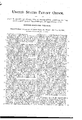
- the object of my invention is to provide the pedal of a sewing-machine treadle witha neat and compact carpet padding on its upper surface, and also to secure the pedal to its supporting-rod, so that it will tilt thereon with as little friction as. possible, to obtain an easy movement of the treadle mechanism; and I accomplish this by the construction substantially as hereinafter described, and illustrated in the accompanying drawings, in which Figure I is a plan view of the pedal portion of a sewing-machine treadle made and secured to its supporting-rod according to my invention.
- Fig. II is a vertical section of the same at line A, showing the wooden foot-rest covered with its carpet and secured in place in the pedal.
- Fig. III is a'vertical section at line B of Fig. I. Fig.
- IV is atransverse section of the rod which supports the pedal, and also through a portion of the latter, showing the manner of securing the pedal to the rod, so as to tilt thereon; and Fig. Vis a transverse section of the pedal, showing the method of Se curing the padded foot-rest in position within the pedal-frame.
- 1 represents the rod, which ordinarily extends from one end of the frame of a sewing-machine to the other end, at the bottom, upon which the pedal of the treadle is pivoted; and in this case this rod 1 extends through a hole, 3, in'each end of the frame 2 of the pedal, this frame being of general rectangular form, and provided with cross-bars, as 13, extending from one end of the frame to the other.
- the ends of the frame between the cross-bars 13 are channeled on the inside, with an inwardly-projecting lip or shoulder, 7, above and below the channel, as shown in Fig. V, and a projecting lip or shoulder, 7, is made on the inside of the cross-bars 13, corresponding to and upon the same horizontal plane as the lip or shoulder 7 011 the frame between said cross-bars, as shown in Fig. II.
- the latter has a kerf sawed partially through 6 it midway its length, as at 11.
- the board is bent at the saw-kerf 11 into the form shown in dotted lines in Fig. V, so that each of its ends may be placed into the said channel in the. frame 2, below the upper lip or shoulder, 7, with the pad or web laid upon the board; and when its ends are so placed the board is again straightened, as shown in black lines in Fig. V, which forces it up firmly into position against the lip 7 above the channel in the frame, with the pad or carpet firmly clamped between the upper side of the board, all around its edge, and the lip or shoulder and the board and pad are held in this position bya bar, 10,
- the pedal is secured in position to tilt on the rod 1 by making a tapered cav- 8o ity, as 4, in the upper side of the rod, as shown clearly in Fig.
- a pedal-frame for treadles having a channel made on the inner part of two of its sides, with a projecting lip or shoulder forming the upper side of said channel, and extending around the inside of the other two sides on the 0 same horizontal plane, in combination with a removable foot-board adapted to be inserted into said frame, and'seeured from below, and a pad or web held at its edges between said board and said lip or shoulder, substantially as described.
Landscapes
- Physics & Mathematics (AREA)
- General Physics & Mathematics (AREA)
- Engineering & Computer Science (AREA)
- Automation & Control Theory (AREA)
- Sewing Machines And Sewing (AREA)
Description
(No Model.)
J. H. OSBORN.
SEWING MACHINE TREADLE.
No. 231,392. Patented July 17,1883.
I masses.
. N. EETERS. Fhnwumn n hu. wauhin wn. D. C.
UNITED STATES PATENT OFFICE.
JOHN H. OSBORN, OF SPRINGFIELD,
LEADER SEWING MACHINE CO SEWING- MACHINE TREADLE.
SPECIFICATION forming part of Letters Patent No. 281,39", dated July 1'7, 1883.
' Application filed August 25,1882. (No model.)
To all whom it may concern:
Be it known that I, JOHN H. OSBORN, of Springfield, in the county of Hampden and State of Massachusetts, have invented a new and useful Improvement in Sewing-Machine Treadles, of which the following is aspecification and description.
The object of my invention is to provide the pedal of a sewing-machine treadle witha neat and compact carpet padding on its upper surface, and also to secure the pedal to its supporting-rod, so that it will tilt thereon with as little friction as. possible, to obtain an easy movement of the treadle mechanism; and I accomplish this by the construction substantially as hereinafter described, and illustrated in the accompanying drawings, in which Figure I is a plan view of the pedal portion of a sewing-machine treadle made and secured to its supporting-rod according to my invention. Fig. II is a vertical section of the same at line A, showing the wooden foot-rest covered with its carpet and secured in place in the pedal. Fig. III is a'vertical section at line B of Fig. I. Fig. IV is atransverse section of the rod which supports the pedal, and also through a portion of the latter, showing the manner of securing the pedal to the rod, so as to tilt thereon; and Fig. Vis a transverse section of the pedal, showing the method of Se curing the padded foot-rest in position within the pedal-frame.
In the drawings, 1 represents the rod, which ordinarily extends from one end of the frame of a sewing-machine to the other end, at the bottom, upon which the pedal of the treadle is pivoted; and in this case this rod 1 extends through a hole, 3, in'each end of the frame 2 of the pedal, this frame being of general rectangular form, and provided with cross-bars, as 13, extending from one end of the frame to the other. The ends of the frame between the cross-bars 13 are channeled on the inside, with an inwardly-projecting lip or shoulder, 7, above and below the channel, as shown in Fig. V, and a projecting lip or shoulder, 7, is made on the inside of the cross-bars 13, corresponding to and upon the same horizontal plane as the lip or shoulder 7 011 the frame between said cross-bars, as shown in Fig. II. A
the latter has a kerf sawed partially through 6 it midway its length, as at 11. The board is bent at the saw-kerf 11 into the form shown in dotted lines in Fig. V, so that each of its ends may be placed into the said channel in the. frame 2, below the upper lip or shoulder, 7, with the pad or web laid upon the board; and when its ends are so placed the board is again straightened, as shown in black lines in Fig. V, which forces it up firmly into position against the lip 7 above the channel in the frame, with the pad or carpet firmly clamped between the upper side of the board, all around its edge, and the lip or shoulder and the board and pad are held in this position bya bar, 10,
placed across the lower side of the board, about midway its length, with a screw turned through each end into a threaded hole made in the lower side of the frame, as shown in Figs. II, III, and V. The pedal is secured in position to tilt on the rod 1 by making a tapered cav- 8o ity, as 4, in the upper side of the rod, as shown clearly in Fig. IV, the rod extending through an elongated hole, 3, made in each end of the frame 2; and a screw, 5, having a tapered or rounded end, of less diam cavity 4 in the rod, is turned down through the pedal-frame from above, with its end bearing in the bottom of the cavity 4 in the rod, so that the whole weight of the pedal is borne by the tapered ends of the two screws 5, bean o ing in the two tapered cavities 4 in the rod, the two screws being free to tilt to and fro as the pedal is moved by the operator to work the treadle.
It will be seen that while the tapered ends 5 ofthe screws 5 are free to rock or tilt to and fro in the tapered cavities 4 in the rod 1, the lower part of the frame, directly beneath the holes through which the rod 1 extends, is in such close proximity to the rod that the tar00 shoulder 7; and apad eter than the tapered pered screws are prevented from being accidentally removed from their cavities; and if the points of the screws become worn, the wear may be compensated for by turning the screws 5 in slightly to take up any lost motion, so thatthe pedal may hang firm upon the rod 1 without jarring or lost motion.
By this construction all the friction in the movement of the pedal upon its rod isreduced to a minimum, the pedal simply being rocked to and fro upon the point of the screw 5 in its cavity 4:-
By this construction I am enabled to provide a sewing-machine with a treadlc mechanism which has an easy movement-the treadle-rod being attached to the pedal at the point and the surface of whose pedal is padded, so that in cold weather the feet will not be affected by the extreme coldness of the iron; and 20 should the padding or web become worn, any person may readily detach the foot -boards from the pedal and attach a new pad or web and replace the boards in the pedal.
Having thus described my invention, what I 2 5 claim as new is 1. A pedal-frame for treadles, having a channel made on the inner part of two of its sides, with a projecting lip or shoulder forming the upper side of said channel, and extending around the inside of the other two sides on the 0 same horizontal plane, in combination with a removable foot-board adapted to be inserted into said frame, and'seeured from below, and a pad or web held at its edges between said board and said lip or shoulder, substantially as described.
2. The combination, with a pedal-frame having an elongated hole in each end, of a pedalsupporting rod extending horizontally through said hole and provided with tapered cavities 40 in its upper side, and screw-pivots turned into said frame, with their tapered ends proj eeting into said elongated hole, and having theirbearings in said cavities, to tilt to and fro therein, substantially as described.
JOHN H. OSBORN.
XVitnesses:
T. A. CURTIS, Crms. H. Woon.
Publications (1)
| Publication Number | Publication Date |
|---|---|
| US281392A true US281392A (en) | 1883-07-17 |
Family
ID=2350602
Family Applications (1)
| Application Number | Title | Priority Date | Filing Date |
|---|---|---|---|
| US281392D Expired - Lifetime US281392A (en) | Sewing-machine treadle |
Country Status (1)
| Country | Link |
|---|---|
| US (1) | US281392A (en) |
-
0
- US US281392D patent/US281392A/en not_active Expired - Lifetime
Similar Documents
| Publication | Publication Date | Title |
|---|---|---|
| US550409A (en) | Island | |
| US281392A (en) | Sewing-machine treadle | |
| US493696A (en) | Attachment for cycle-pedals | |
| US1120460A (en) | Foot-rest attachment for automobile controlling-levers. | |
| US276502A (en) | tatum | |
| US275966A (en) | Sewing-machine | |
| US168182A (en) | Improvement in sewing-machine casters | |
| US499205A (en) | bryon | |
| US543806A (en) | Cycle-pedal | |
| US119724A (en) | Improvement in sewing-machine treadles | |
| US112162A (en) | Improvement in treadles for sewing-machines | |
| US147574A (en) | Improvement in sewing-machine casters | |
| US292573A (en) | pasfield | |
| US255751A (en) | Treadle | |
| US333262A (en) | shepherd | |
| US101843A (en) | Improvement in casters for sewing-machines | |
| US601985A (en) | Hiram p | |
| US1223860A (en) | Edge-guide attachment for sewing-machines. | |
| US776138A (en) | Garment-fitting stand. | |
| US1203260A (en) | Foot-supporting attachment for desks, &c. | |
| US393342A (en) | John bau | |
| US745907A (en) | Ironing-board. | |
| US328232A (en) | Riding-saddle | |
| US133177A (en) | Improvement in treadles for sewing-machines | |
| US295623A (en) | Riding-saddle |