US2743829A - ballard - Google Patents
ballard Download PDFInfo
- Publication number
- US2743829A US2743829A US2743829DA US2743829A US 2743829 A US2743829 A US 2743829A US 2743829D A US2743829D A US 2743829DA US 2743829 A US2743829 A US 2743829A
- Authority
- US
- United States
- Prior art keywords
- teeth
- debris
- belt
- belts
- conveyor
- Prior art date
- Legal status (The legal status is an assumption and is not a legal conclusion. Google has not performed a legal analysis and makes no representation as to the accuracy of the status listed.)
- Expired - Lifetime
Links
- 238000010408 sweeping Methods 0.000 description 14
- 235000000396 iron Nutrition 0.000 description 12
- 241001417527 Pempheridae Species 0.000 description 10
- 229910000746 Structural steel Inorganic materials 0.000 description 10
- 230000003028 elevating Effects 0.000 description 6
- 238000009825 accumulation Methods 0.000 description 4
- 230000015572 biosynthetic process Effects 0.000 description 4
- 230000000875 corresponding Effects 0.000 description 4
- 238000005755 formation reaction Methods 0.000 description 4
- XEEYBQQBJWHFJM-UHFFFAOYSA-N iron Chemical compound [Fe] XEEYBQQBJWHFJM-UHFFFAOYSA-N 0.000 description 4
- 230000014759 maintenance of location Effects 0.000 description 4
- 239000000463 material Substances 0.000 description 4
- 239000002184 metal Substances 0.000 description 4
- 229910052751 metal Inorganic materials 0.000 description 4
- 241001553178 Arachis glabrata Species 0.000 description 2
- 229940035295 Ting Drugs 0.000 description 2
- 238000004873 anchoring Methods 0.000 description 2
- 230000005540 biological transmission Effects 0.000 description 2
- 229910052742 iron Inorganic materials 0.000 description 2
- 238000004519 manufacturing process Methods 0.000 description 2
- 238000005192 partition Methods 0.000 description 2
- 239000002759 woven fabric Substances 0.000 description 2
Images

Classifications
-
- B—PERFORMING OPERATIONS; TRANSPORTING
- B65—CONVEYING; PACKING; STORING; HANDLING THIN OR FILAMENTARY MATERIAL
- B65G—TRANSPORT OR STORAGE DEVICES, e.g. CONVEYORS FOR LOADING OR TIPPING, SHOP CONVEYOR SYSTEMS OR PNEUMATIC TUBE CONVEYORS
- B65G19/00—Conveyors comprising an impeller or a series of impellers carried by an endless traction element and arranged to move articles or materials over a supporting surface or underlying material, e.g. endless scraper conveyors
- B65G19/18—Details
- B65G19/20—Traction chains, ropes, or cables
-
- E—FIXED CONSTRUCTIONS
- E01—CONSTRUCTION OF ROADS, RAILWAYS, OR BRIDGES
- E01H—STREET CLEANING; CLEANING OF PERMANENT WAYS; CLEANING BEACHES; DISPERSING OR PREVENTING FOG IN GENERAL CLEANING STREET OR RAILWAY FURNITURE OR TUNNEL WALLS
- E01H1/00—Removing undesirable matter from roads or like surfaces, with or without moistening of the surface
- E01H1/02—Brushing apparatus, e.g. with auxiliary instruments for mechanically loosening dirt
- E01H1/04—Brushing apparatus, e.g. with auxiliary instruments for mechanically loosening dirt taking- up the sweepings, e.g. for collecting, for loading
- E01H1/042—Brushing apparatus, e.g. with auxiliary instruments for mechanically loosening dirt taking- up the sweepings, e.g. for collecting, for loading the loading means being an endless belt or an auger
Definitions
- This invention relates to improved endless conveyors of a type particularly adapted in certain respects for use in street sweeping machines.
- Conventional street sweepers generally include a collection chamber within which debris taken from the street is accumulated, and an inclined endless conveyor acting to elevate debris from a level near the street into the chamber.
- This conveyor comprises an endless body, usually a flexible belt, and a number of elements projecting from and movable with the body to engage the debris and advance it upwardly along an inclined ramp into the collection chamber.
- the conveyor body or belt preferably is provided with a series of teeth along one side to mesh with and be positively driven by an associated sprocket wheel.
- An important object of the invention is to provide, in a conveyor of the above character, improved means for mounting the debris or work engaging elements to the conveyor body, in a manner assuring completely effective retention and positioning of the elements during operation of the conveyor.
- Particularly contemplated is a type of mounting adapted to minimize the extent to which the work engaging elements may be deflected relative to the conveyor body by the resistance of the debris being handled.
- I employ for mount- 4 ing each of the work engaging elements to the conveyor body a special mounting element which extends directly into and is preferably anchored securely Within, the mate rial of the flexible conveyor body.
- the flexible body may be formed of rubber, and the mounting element may comprise a rigid metallic member embedded in and vulcanized to the rubber.
- teeth like the rest of the belt body, may be formed of rubber, and the mounting elements may comprise studs secured to plates embedded in and bonded to the rubber teeth.
- the employment of such mounting elements anchored directly to the teeth of the belt has proven especially effective in positioning the work engaging elements during the portions of their travel when the belt is engaged by a sprocket wheel, since the teeth are then positively held by the teeth of the wheel, and the mounting elements attached to the teeth are therefore also positively positioned.
- each of the teeth to which a mounting element is secured is formed separately from and removably attached to the belt body.
- the mounting studs may have portions projecting from these removable teeth and extending through openings in the belt body to connect to the work engaging elements at a side of the belt opposite the side at which the teeth are carried. Fastening of the work engaging elements to the studs then serves to clamp the belt body between the teeth and work engaging elements, and thus securely fasten both of these parts to the belt.
- the work engaging elements may each comprise a flexible squeegee member carried and reinforced by a rigid angle iron fastened to the belt.
- I When the present conveyors are employed in street sweeping machines, I preferably employ a conveyor system including two spaced and parallel belts, and a number of debris engaging elements mounted at their opposite ends to and extending horizontally between the two belts.
- one of the interengaging parts may be of such open formation as to permit any debris trapped between the members to freely escape.
- the portions of one of the parts, preferably the sprocket wheel, between its successive teeth may have transverse dimensions substantially smaller than the teeth themselves, to form alongside those portions a number of passages or openings through which debris may escape from the spaces between the teeth of that member.
- these inter-tooth por tions are desirably formed to taper transversely of the wheel to relatively sharp edges, in a manner to cut any dirt mass which may be present into two pieces and then displace the two pieces in opposite directions and out of the space between the wheel and belt.
- Fig. l is a side view of a street sweeping machine embodying the invention, the side wall of the machine being partially broken away to reveal the inner debris elevating conveyor;
- Fig. 2 is an enlarged fragmentary side view of one of the conveyor belts, the associated debris engaging elements, and one of the belt driving sprocket wheels;
- Fig. 3 is an axial section through the belt and sprocket wheel of Fig. 2, taken along line 33 of that figure;
- Fig. 4 is an enlarged fragmentary section through one of the debris advancing elements and the portion of one of the endless belts to which that element is mounted;
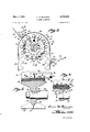
- Fig. 5 is a perspective view of the elevator conveyor assembly
- Fig. 6 is a fragmentary section taken on line 66 of Fig. 2.
- a street sweep-machine or vehicle 10 having the usual forward gutter brush 11 and rear transverse main brush 12, both of which are driven by the engine of the vehicle through a suitable drive system 13.
- Transverse brush 12 acts to sweep the debris l4 forwardly from the street surface 15 onto the lower portion of an inclined elevator ramp 16.
- This ramp may be formed of sheet metal and preferably extends substantially entirely across the transverse extent of the street sweeping machine.
- the debris is advanced upwardly along ramp 16 by an elevator conveyor assembly generally indicated at 17, and falls from an upper end 13 of the ramp into a debris accumulating chamber 19 at the forward end of the machine.
- the space within which conveyor 17 is contained is closed along the upper side and upper end of the conveyor by a sheet metal wall or partition 20.
- the conveyor 17 includes a pair of laterally spaced, parallel, endless belts 21 positioned at opposite sides of the vehicle and inclined at an angle corresponding to the inclination of ramp 16. For advancing debris upwardly along ramp 16, a number of p'airs of mounting studs 36'.
- each belt presents a series of trans- Velbely extending spaced teeth 29 for engaging the whet-.1522 and 23.
- teeth--29 may be formed of a resilient rubber, and 'ri tdsfoftliem are preferably molded integrally with the itibbt bofiy'of the belt. Certain ones of the teeth 29a, llo we'v er at predetermined locations spaced along each hilt, are formedseparately from' and are removably atticlifible to the body of the belt. These separately formed removable teeth 29a are preferably formed of inflame of rubber as the belt body and other teeth, shdsreempioyea for anchoring the debris engaging units Wildfire belts. H
- Each of the transvers'e'debris engaging units 30 includes iffl'arisversely extending elongated angle iron 31, having portion 32 "extending transversely across the fih'te'l” surfaces of the two belts, and an outwardly projec'ting portion 33 to which is mounted a flexible transvrsily "extending 'sheet-like squeegee element 34.
- the sw ageeeiemem 34 maybe formed of a suitable resilient rubber, andfproj'ects into engagement with ramp 16 in vvipetlbris u'p ⁇ vardly along the ramp as the belts are driven.
- squeegee 34 may be attached to angle iron 31in any suitable manner, as by rivets 35.
- Each at the angle irons 31 is fastened at its opposite ends to corresponding portions of the two belts 21 by
- the two studs at each end of each angle iron extend through a pair of openings 37 in tlie ma of one of the belts, and are embedded in and bonded to one of the removable rubber teeth 29a of that belt.
- the studs are welded or otherwise sedared to a plate 38, which is embedded in and extends li'hils'wrsely across a major portion of the removable tooth.
- studs'36 carry nuts 39, which 'arb tightened against the angle iron to securely fasten the debris engaging squeegees to the belts.
- the sprocket wheels 22 and 23 are of a special formasen reassure efl'ective transmission of driving force to the belts, while at the same time preventing the accumuldflon of dirt or other debris within the inter-tooth of the wheels.
- Each of the sprocket wheels has thub portion 40 of relatively small transverse dimension, carrying a series of circularly spaced belt engaging teeth 4! of a width considerably greater than the hub.
- the width of teeth'41 desirably corresponds to the width of belt 21 (see Fig. 3).
- the sprocket wheel hub terminates outwardly in a number of intermediate inwardly recessed portions 42 having dimensions transversely of the wheel substantially smaller than the teeth.
- inter'tooth portions of the wheel desirably hper rndiallyjoutwardly and transversely of the wheel from the hub width to a relatively sharp outer knife edge 43; -As best SCCBiD-FigrG', this knife edge serves to cut into two portions any mass of dirt or debris trapped between the belt teeth and the inter-tooth portions 42 of the sprocket wheel and to then displace the two masses of debris in opposite directions from between the belt and wheel.
- teeth 41 are spaced apart along their entire radial extents, to form between their radially inner portions a number of openings or passages 141 through which debris may escape radially inwardly from the spaces between teeth.
- these recesses preferably have areas greater than the belt teeth (see Fig. 2), so that the belt teeth are spaced from the sprocket wheel along their sides 44, to further assure against difficulties resulting from the presence of debris between the belt andsprocket wheel.
- the belt teeth may however be formed to directly engage the sharp edges 43 of the sprocket wheel at the peaks 43 of the teeth, to assure an effective cutting of the debris mass into two parts.
- the street sweeping vehicle moves to the right as seen in Fig. 1, with brushes 11 and 12 and conveyor '17 continuously operating.
- Brush l1 sweeps debris from a gutter along which the vehicle is driven, while brush 12, rotating in counterclockwise direction as seen in Fig. l, sweeps debris forwardlyonto the lower slightly inclined portion of ramp 16.
- Endless conveyor 17 moving in a counterclockwise direction'as seen in Fig. l advances the debris upwardly along ramp'16 and into chamber 19.
- the debris moving along ramp 16 is directly engaged and advanced by squeegee elements 34.
- the special mounting of elements 34 to the belts as shown 'in Fig. 4, positively positions the Squeegees in their desired outwardly projecting positions, and prevents unwanted deflection of the Squeegees relative to the belts under the influence of the debris being elevated.
- a debris chamber having an opening in an upper portion thereof, an inclined ramp along which debris may be elevated toward said opening for delivery into said chamber, and means for elevating debris along said ramp into the chamber
- said elevating means including a pair of inclined laterally spaced endless flexible rubber belts, toothed sprocket wheels mounting said belts for endless movement, rubber teeth carried by said belts and engaging the teeth of said sprocket Wheels, some of said teeth being formed separately from and removabl'y attached to the belt, angle irons extending transversely between and across said belts at spaced locationo'ns the'r'eal'ong, rubber squeegee elements carried by said angle" iron and movable upwardly along the upper side of said ramp to advance the debris therealong, studs embedded in and bonded to said removable belt teeth and projecting therefrom through openings in said belt and then through openings in said angle irons, nuts threaded onto said 'studs to fasten said angle irons and removable teeth to the belt
- a 'streetswe'epirig motor vehicle comprising a debrisch'amb'er having an opening in an upper'portion thereof, a conveyor operable to elevate debris from a level'near the street and feed it into said chamber through said upper opening, and an inclined ramp along which debris is elevatedinto said chamber by said conveyor, said conveyor comprising a pair of inclined essentially parallel laterally spaced endless flexible rubber belts having rubber teeth spaced there'alon'g, sprocket wheels for driving said belts and'having teeth inter'fitting with said belt teeth, andunits carried by and extending transversely" between said endless rubber belts a'nd'a'cting to engage and elevate debris "asth'e belts move, eachjdr saidrl'lbberQbelts and -iriost or itsbarrid'iiibbbr teeth being formed integrally.
- said debris engaging units include angle irons extending transversely between said belts at locations spaced therealong, and rubber squeegee elements carried by said angle irons for moving along said ramp and engaging and acting against the debris.
- a debris chamber having an opening in an upper portion thereof, a conveyor operable to elevate debris from a level near the street and feed it into said chamber through said upper opening, and an inclined ramp along which debris is elevated into said chamber by said conveyor
- said conveyor comprising a pair of in- .clined essentially parallel laterally spaced endless flexible belts having teeth spaced therealong, said belts and teeth being formed of resiliently deformable material, sprocket wheels for driving said belts and having teeth interfitting with said belt teeth, and units carried by and extending transversely between said endless belts and acting to engage and elevate debris as the belts move, each of said belts and most of its carried teeth being formed integrally.
Landscapes
- Engineering & Computer Science (AREA)
- Architecture (AREA)
- Civil Engineering (AREA)
- Structural Engineering (AREA)
- Mechanical Engineering (AREA)
- Belt Conveyors (AREA)
Description
May 1, 1956 L. M. BALLARD SWEEPER CONVEYORS 2 Sheets-Sheet 1 Filed Dec. 24, 1951 lows M BALL/42D,
INVENTOR.
BY M
J4TTOENEY.
y 956 1.. M. BALLARD 2,743,829
SWEEPER CONVEYORS Filed Dec. 24, 1951 2 sh t s 2 IIIIIIIIIIIIIIIUllI/IIII I I 3 laws M. BALLAED,
INVENTOR. 43 m BY w ATTOQ/VEY.
United States Patent SWEEPER CONVEYORS Louis M. Ballard, Duarte, Calif., assignor to Wayne Manufacturing Company, Pomona, Califl, a corporation of California Application December 24, 1951, Serial No. 263,089
4 Claims. (Cl. 214-3336) This invention relates to improved endless conveyors of a type particularly adapted in certain respects for use in street sweeping machines.
Conventional street sweepers generally include a collection chamber within which debris taken from the street is accumulated, and an inclined endless conveyor acting to elevate debris from a level near the street into the chamber. This conveyor comprises an endless body, usually a flexible belt, and a number of elements projecting from and movable with the body to engage the debris and advance it upwardly along an inclined ramp into the collection chamber. The conveyor body or belt preferably is provided with a series of teeth along one side to mesh with and be positively driven by an associated sprocket wheel.
An important object of the invention is to provide, in a conveyor of the above character, improved means for mounting the debris or work engaging elements to the conveyor body, in a manner assuring completely effective retention and positioning of the elements during operation of the conveyor. Particularly contemplated is a type of mounting adapted to minimize the extent to which the work engaging elements may be deflected relative to the conveyor body by the resistance of the debris being handled.
In accordance with the invention, I employ for mount- 4 ing each of the work engaging elements to the conveyor body a special mounting element which extends directly into and is preferably anchored securely Within, the mate rial of the flexible conveyor body. The flexible body may be formed of rubber, and the mounting element may comprise a rigid metallic member embedded in and vulcanized to the rubber. In order to assure most effective mounting and most accurate positioning of the work engaging elements relative to the body, I prefer to employ a type of belt body having at one of its sides a series of teeth for meshing with a driving sprocket wheel, and to then form each of the mounting elements to extend. into and be anchored within one of the teeth. These teeth, like the rest of the belt body, may be formed of rubber, and the mounting elements may comprise studs secured to plates embedded in and bonded to the rubber teeth. The employment of such mounting elements anchored directly to the teeth of the belt has proven especially effective in positioning the work engaging elements during the portions of their travel when the belt is engaged by a sprocket wheel, since the teeth are then positively held by the teeth of the wheel, and the mounting elements attached to the teeth are therefore also positively positioned.
Preferably, each of the teeth to which a mounting element is secured is formed separately from and removably attached to the belt body. The mounting studs may have portions projecting from these removable teeth and extending through openings in the belt body to connect to the work engaging elements at a side of the belt opposite the side at which the teeth are carried. Fastening of the work engaging elements to the studs then serves to clamp the belt body between the teeth and work engaging elements, and thus securely fasten both of these parts to the belt. The work engaging elements may each comprise a flexible squeegee member carried and reinforced by a rigid angle iron fastened to the belt.
When the present conveyors are employed in street sweeping machines, I preferably employ a conveyor system including two spaced and parallel belts, and a number of debris engaging elements mounted at their opposite ends to and extending horizontally between the two belts.
Further features of the invention have to do with a special formation of the interengaging teeth of the sprocket wheel and belt, in a manner to prevent the accumulation of dirt and debris between those teeth.
In particular, I prevent such dirt accumulation by forming one of the interengaging parts to be of such open formation as to permit any debris trapped between the members to freely escape. For this purpose, the portions of one of the parts, preferably the sprocket wheel, between its successive teeth may have transverse dimensions substantially smaller than the teeth themselves, to form alongside those portions a number of passages or openings through which debris may escape from the spaces between the teeth of that member. Also, these inter-tooth por tions are desirably formed to taper transversely of the wheel to relatively sharp edges, in a manner to cut any dirt mass which may be present into two pieces and then displace the two pieces in opposite directions and out of the space between the wheel and belt.
The above and other. features and objects of the present invention will be better understood from the following detailed description of the typical embodiment illustrated in the accompanying drawings, in which:
Fig. l is a side view of a street sweeping machine embodying the invention, the side wall of the machine being partially broken away to reveal the inner debris elevating conveyor;
Fig. 2 is an enlarged fragmentary side view of one of the conveyor belts, the associated debris engaging elements, and one of the belt driving sprocket wheels;
Fig. 3 is an axial section through the belt and sprocket wheel of Fig. 2, taken along line 33 of that figure;
Fig. 4 is an enlarged fragmentary section through one of the debris advancing elements and the portion of one of the endless belts to which that element is mounted;
Fig. 5 is a perspective view of the elevator conveyor assembly; and
Fig. 6 is a fragmentary section taken on line 66 of Fig. 2.
I have represented in Fig. l a street sweep-machine or vehicle 10, having the usual forward gutter brush 11 and rear transverse main brush 12, both of which are driven by the engine of the vehicle through a suitable drive system 13. Transverse brush 12 acts to sweep the debris l4 forwardly from the street surface 15 onto the lower portion of an inclined elevator ramp 16. This ramp may be formed of sheet metal and preferably extends substantially entirely across the transverse extent of the street sweeping machine. The debris is advanced upwardly along ramp 16 by an elevator conveyor assembly generally indicated at 17, and falls from an upper end 13 of the ramp into a debris accumulating chamber 19 at the forward end of the machine. The space within which conveyor 17 is contained is closed along the upper side and upper end of the conveyor by a sheet metal wall or partition 20.
Referring now to Fig. 5, the conveyor 17 includes a pair of laterally spaced, parallel, endless belts 21 positioned at opposite sides of the vehicle and inclined at an angle corresponding to the inclination of ramp 16. For advancing debris upwardly along ramp 16, a number of p'airs of mounting studs 36'.
3 horizontallybetweeneorresponding portions of belts-21, and move upwardly along up r surface of ramp 16 in correspondence with the "m Brits. ms sna lswei-eaas of the belts eitt'endab'o'ut Hill "lspro cke't wheels 22 and 23, the two upper Wimnoveinenm'r the upper extents of those belts.
'ofbe'lfs 2 1'eoinprises an elongated endless flexible lateral width is preferably greater than its s. This belt body may be formed of a suitable itlofihbut flexibl'e rubb'er, which is desirably reinforced or more plies of woven fabric 28 embedded in ifiia'eitending along the entire length of the belt body. Xt its side, each belt presents a series of trans- Velbely extending spaced teeth 29 for engaging the whet-.1522 and 23.
teeth--29 may be formed of a resilient rubber, and 'ri tdsfoftliem are preferably molded integrally with the itibbt bofiy'of the belt. Certain ones of the teeth 29a, llo we'v er at predetermined locations spaced along each hilt, are formedseparately from' and are removably atticlifible to the body of the belt. These separately formed removable teeth 29a are preferably formed of inflame of rubber as the belt body and other teeth, shdsreempioyea for anchoring the debris engaging units Wildfire belts. H
I Each of the transvers'e'debris engaging units 30 includes iffl'arisversely extending elongated angle iron 31, having portion 32 "extending transversely across the fih'te'l" surfaces of the two belts, and an outwardly projec'ting portion 33 to which is mounted a flexible transvrsily "extending 'sheet-like squeegee element 34. The sw ageeeiemem 34 maybe formed of a suitable resilient rubber, andfproj'ects into engagement with ramp 16 in vvipetlbris u'p\vardly along the ramp as the belts are driven. squeegee 34 may be attached to angle iron 31in any suitable manner, as by rivets 35.
Each at the angle irons 31 is fastened at its opposite ends to corresponding portions of the two belts 21 by The two studs at each end of each angle iron extend through a pair of openings 37 in tlie ma of one of the belts, and are embedded in and bonded to one of the removable rubber teeth 29a of that belt.- For assuring positive retention of the studs to that removable tooth, the studs are welded or otherwise sedared to a plate 38, which is embedded in and extends li'hils'wrsely across a major portion of the removable tooth. At their outer ends, studs'36 carry nuts 39, which 'arb tightened against the angle iron to securely fasten the debris engaging squeegees to the belts.
The sprocket wheels 22 and 23 are of a special formasen reassure efl'ective transmission of driving force to the belts, while at the same time preventing the accumuldflon of dirt or other debris within the inter-tooth of the wheels. Each of the sprocket wheels has thub portion 40 of relatively small transverse dimension, carrying a series of circularly spaced belt engaging teeth 4! of a width considerably greater than the hub. The width of teeth'41 desirably corresponds to the width of belt 21 (see Fig. 3). Between teeth 53., the sprocket wheel hub terminates outwardly in a number of intermediate inwardly recessed portions 42 having dimensions transversely of the wheel substantially smaller than the teeth. These inter'tooth portions of the wheel desirably hper rndiallyjoutwardly and transversely of the wheel from the hub width to a relatively sharp outer knife edge 43; -As best SCCBiD-FigrG', this knife edge serves to cut into two portions any mass of dirt or debris trapped between the belt teeth and the inter-tooth portions 42 of the sprocket wheel and to then displace the two masses of debris in opposite directions from between the belt and wheel. At opposite sides of these inter-tooth portions 42 of the wheel, teeth 41 are spaced apart along their entire radial extents, to form between their radially inner portions a number of openings or passages 141 through which debris may escape radially inwardly from the spaces between teeth. It is also noted that even at the smallest portions of the inter-tooth recesses of the sprocket wheel, i. e. at the locations of knife edges 43, these recesses preferably have areas greater than the belt teeth (see Fig. 2), so that the belt teeth are spaced from the sprocket wheel along their sides 44, to further assure against difficulties resulting from the presence of debris between the belt andsprocket wheel. The belt teeth may however be formed to directly engage the sharp edges 43 of the sprocket wheel at the peaks 43 of the teeth, to assure an effective cutting of the debris mass into two parts.
In use, the street sweeping vehicle moves to the right as seen in Fig. 1, with brushes 11 and 12 and conveyor '17 continuously operating. Brush l1 sweeps debris from a gutter along which the vehicle is driven, while brush 12, rotating in counterclockwise direction as seen in Fig. l, sweeps debris forwardlyonto the lower slightly inclined portion of ramp 16. Endless conveyor 17 moving in a counterclockwise direction'as seen in Fig. l advances the debris upwardly along ramp'16 and into chamber 19.
The debris moving along ramp 16 is directly engaged and advanced by squeegee elements 34. The special mounting of elements 34 to the belts, as shown 'in Fig. 4, positively positions the Squeegees in their desired outwardly projecting positions, and prevents unwanted deflection of the Squeegees relative to the belts under the influence of the debris being elevated.
I. claim:
I. In a street sweeper, a debris chamber having an opening in an upper portion thereof, an inclined ramp along which debris may be elevated toward said opening for delivery into said chamber, and means for elevating debris along said ramp into the chamber, said elevating means including a pair of inclined laterally spaced endless flexible rubber belts, toothed sprocket wheels mounting said belts for endless movement, rubber teeth carried by said belts and engaging the teeth of said sprocket Wheels, some of said teeth being formed separately from and removabl'y attached to the belt, angle irons extending transversely between and across said belts at spaced locatio'ns the'r'eal'ong, rubber squeegee elements carried by said angle" iron and movable upwardly along the upper side of said ramp to advance the debris therealong, studs embedded in and bonded to said removable belt teeth and projecting therefrom through openings in said belt and then through openings in said angle irons, nuts threaded onto said 'studs to fasten said angle irons and removable teeth to the belts, and plates attached to said studs and embedded in said removable teeth.
2.111 a 'streetswe'epirig motor vehicle, the combination comprising a debrisch'amb'er having an opening in an upper'portion thereof, a conveyor operable to elevate debris from a level'near the street and feed it into said chamber through said upper opening, and an inclined ramp along which debris is elevatedinto said chamber by said conveyor, said conveyor comprising a pair of inclined essentially parallel laterally spaced endless flexible rubber belts having rubber teeth spaced there'alon'g, sprocket wheels for driving said belts and'having teeth inter'fitting with said belt teeth, andunits carried by and extending transversely" between said endless rubber belts a'nd'a'cting to engage and elevate debris "asth'e belts move, eachjdr saidrl'lbberQbelts and -iriost or itsbarrid'iiibbbr teeth being formed integrally.
3. In a street sweeping motor vehicle, the combination as recited in claim 2, in which said debris engaging units include angle irons extending transversely between said belts at locations spaced therealong, and rubber squeegee elements carried by said angle irons for moving along said ramp and engaging and acting against the debris.
4. In a street sweeping motor vehicle, the combination comprising a debris chamber having an opening in an upper portion thereof, a conveyor operable to elevate debris from a level near the street and feed it into said chamber through said upper opening, and an inclined ramp along which debris is elevated into said chamber by said conveyor, said conveyor comprising a pair of in- .clined essentially parallel laterally spaced endless flexible belts having teeth spaced therealong, said belts and teeth being formed of resiliently deformable material, sprocket wheels for driving said belts and having teeth interfitting with said belt teeth, and units carried by and extending transversely between said endless belts and acting to engage and elevate debris as the belts move, each of said belts and most of its carried teeth being formed integrally.
References Cited in the file of this patent UNITED STATES PATENTS Dunn Aug. 2, Sargent et al. Oct. 16, MacPhail et al. Apr. 2, Beckwith Jan. 11, Tinsley Oct. 28, Smith Apr. 28, Wentz July 28, White Feb. 22, Sinden Jan. 7, Peterson Dec. 2, Fees Aug. 14, Flynn et al. Feb. 8, Place Dec. 19, Hannon Jan. 16, Bendall Feb. 10, Scranton Mar. 15,
Publications (1)
| Publication Number | Publication Date |
|---|---|
| US2743829A true US2743829A (en) | 1956-05-01 |
Family
ID=3445708
Family Applications (1)
| Application Number | Title | Priority Date | Filing Date |
|---|---|---|---|
| US2743829D Expired - Lifetime US2743829A (en) | ballard |
Country Status (1)
| Country | Link |
|---|---|
| US (1) | US2743829A (en) |
Cited By (16)
| Publication number | Priority date | Publication date | Assignee | Title |
|---|---|---|---|---|
| US2930478A (en) * | 1958-07-23 | 1960-03-29 | Ruffino David | Conveyor belt |
| US2950827A (en) * | 1956-06-07 | 1960-08-30 | Burgdorff Henry | Free-floating street sweeper elevator |
| US2955701A (en) * | 1957-11-12 | 1960-10-11 | Joe Lowe Corp | Tray for cooling and proofing bakery products |
| US2966984A (en) * | 1955-09-15 | 1961-01-03 | Jeffrey Mfg Co | Portable conveyor apparatus |
| DE1658386B1 (en) * | 1967-04-28 | 1971-05-27 | Holms Industri Ab | Conveyor device for sweepers |
| US4023671A (en) * | 1974-12-10 | 1977-05-17 | Continental Gummi-Werke Aktiengesellschaft | Connection for the ends of supporting straps of an endless bar belt conveyor |
| US4516285A (en) * | 1982-08-20 | 1985-05-14 | Le Materiel De Voirie, Sarl | Pick-up sweeper of the type with elevating conveyor with dirt distributing device in the dirt collecting receptacle |
| US4697693A (en) * | 1984-04-23 | 1987-10-06 | Kimberly-Clark Corporation | Conveying systems |
| US4765073A (en) * | 1986-05-20 | 1988-08-23 | Richard Cloutier | Snow blower with vertical endless belt digger |
| US4897183A (en) * | 1987-06-10 | 1990-01-30 | Lewis Bros. Mfg. Inc. | Litter screening and separating apparatus |
| DE4031377A1 (en) * | 1990-04-06 | 1991-10-24 | Sueddeutsche Kalkstickstoff | Explosive dust sweeping machine - hurls by rotary drum into trough with conveyor discharging into open hopper |
| US20030229957A1 (en) * | 2002-06-12 | 2003-12-18 | Skinner Robert Harvey Hall | Conveyor for mechanical street sweeper |
| US20110220465A1 (en) * | 2010-03-09 | 2011-09-15 | Marchesini Group S.P.A. | Conveyor For Transferring Articles |
| US20150173298A1 (en) * | 2013-12-23 | 2015-06-25 | Ea Broekema Bv | Sugarcane Harvesting Machine |
| US20150223429A1 (en) * | 2012-09-27 | 2015-08-13 | Lely Patent N.V. | Self-propelled animal-shed vehicle for removing manure and an assembly of such an animal-shed vehicle and an animal-shed floor |
| EP2982234A1 (en) | 2014-08-08 | 2016-02-10 | Deere & Company | Inclined conveyor for an agricultural combine harvester having flexible traction elements and removable bolts for attaching conveyor slats |
Citations (15)
| Publication number | Priority date | Publication date | Assignee | Title |
|---|---|---|---|---|
| US527723A (en) * | 1894-10-16 | sarg-ent | ||
| US536813A (en) * | 1895-04-02 | Sprocket-wheel | ||
| US597096A (en) * | 1898-01-11 | Hay or grain elevator and distributer | ||
| US712020A (en) * | 1902-06-26 | 1902-10-28 | James F Tinsley | Distributer of conveyer belt. |
| US886263A (en) * | 1907-11-29 | 1908-04-28 | John W Smith | Street-cleaner. |
| US1547276A (en) * | 1924-06-13 | 1925-07-28 | Portable Machinery Co | Flexible conveyer flight |
| US2109123A (en) * | 1936-09-12 | 1938-02-22 | E F P Brigham | Guard roller for sweeping machines |
| US2227557A (en) * | 1938-10-14 | 1941-01-07 | Redler Conveyor Co | Conveyer |
| US2264332A (en) * | 1939-07-31 | 1941-12-02 | Clarence J Peterson | Belt conveyer |
| US2381892A (en) * | 1943-12-08 | 1945-08-14 | Henry Brandt | Loader |
| US2461150A (en) * | 1944-06-15 | 1949-02-08 | Theodore P Flynn | Endless track |
| US2534679A (en) * | 1945-07-21 | 1950-12-19 | Charles I Place | Belt drive assembly |
| US2538242A (en) * | 1948-03-11 | 1951-01-16 | Frederic B Stevens Inc | Apparatus for processing workpieces |
| US2627756A (en) * | 1947-07-24 | 1953-02-10 | Wilfrid H Bendall | Power transmission chain |
| US2704150A (en) * | 1950-12-13 | 1955-03-15 | Allis Chalmers Mfg Co | Draper type pickup |
-
0
- US US2743829D patent/US2743829A/en not_active Expired - Lifetime
Patent Citations (15)
| Publication number | Priority date | Publication date | Assignee | Title |
|---|---|---|---|---|
| US527723A (en) * | 1894-10-16 | sarg-ent | ||
| US536813A (en) * | 1895-04-02 | Sprocket-wheel | ||
| US597096A (en) * | 1898-01-11 | Hay or grain elevator and distributer | ||
| US712020A (en) * | 1902-06-26 | 1902-10-28 | James F Tinsley | Distributer of conveyer belt. |
| US886263A (en) * | 1907-11-29 | 1908-04-28 | John W Smith | Street-cleaner. |
| US1547276A (en) * | 1924-06-13 | 1925-07-28 | Portable Machinery Co | Flexible conveyer flight |
| US2109123A (en) * | 1936-09-12 | 1938-02-22 | E F P Brigham | Guard roller for sweeping machines |
| US2227557A (en) * | 1938-10-14 | 1941-01-07 | Redler Conveyor Co | Conveyer |
| US2264332A (en) * | 1939-07-31 | 1941-12-02 | Clarence J Peterson | Belt conveyer |
| US2381892A (en) * | 1943-12-08 | 1945-08-14 | Henry Brandt | Loader |
| US2461150A (en) * | 1944-06-15 | 1949-02-08 | Theodore P Flynn | Endless track |
| US2534679A (en) * | 1945-07-21 | 1950-12-19 | Charles I Place | Belt drive assembly |
| US2627756A (en) * | 1947-07-24 | 1953-02-10 | Wilfrid H Bendall | Power transmission chain |
| US2538242A (en) * | 1948-03-11 | 1951-01-16 | Frederic B Stevens Inc | Apparatus for processing workpieces |
| US2704150A (en) * | 1950-12-13 | 1955-03-15 | Allis Chalmers Mfg Co | Draper type pickup |
Cited By (21)
| Publication number | Priority date | Publication date | Assignee | Title |
|---|---|---|---|---|
| US2966984A (en) * | 1955-09-15 | 1961-01-03 | Jeffrey Mfg Co | Portable conveyor apparatus |
| US2950827A (en) * | 1956-06-07 | 1960-08-30 | Burgdorff Henry | Free-floating street sweeper elevator |
| US2955701A (en) * | 1957-11-12 | 1960-10-11 | Joe Lowe Corp | Tray for cooling and proofing bakery products |
| US2930478A (en) * | 1958-07-23 | 1960-03-29 | Ruffino David | Conveyor belt |
| DE1658386B1 (en) * | 1967-04-28 | 1971-05-27 | Holms Industri Ab | Conveyor device for sweepers |
| US4023671A (en) * | 1974-12-10 | 1977-05-17 | Continental Gummi-Werke Aktiengesellschaft | Connection for the ends of supporting straps of an endless bar belt conveyor |
| US4516285A (en) * | 1982-08-20 | 1985-05-14 | Le Materiel De Voirie, Sarl | Pick-up sweeper of the type with elevating conveyor with dirt distributing device in the dirt collecting receptacle |
| US4697693A (en) * | 1984-04-23 | 1987-10-06 | Kimberly-Clark Corporation | Conveying systems |
| US4765073A (en) * | 1986-05-20 | 1988-08-23 | Richard Cloutier | Snow blower with vertical endless belt digger |
| US4897183A (en) * | 1987-06-10 | 1990-01-30 | Lewis Bros. Mfg. Inc. | Litter screening and separating apparatus |
| DE4031377A1 (en) * | 1990-04-06 | 1991-10-24 | Sueddeutsche Kalkstickstoff | Explosive dust sweeping machine - hurls by rotary drum into trough with conveyor discharging into open hopper |
| US20030229957A1 (en) * | 2002-06-12 | 2003-12-18 | Skinner Robert Harvey Hall | Conveyor for mechanical street sweeper |
| US20110220465A1 (en) * | 2010-03-09 | 2011-09-15 | Marchesini Group S.P.A. | Conveyor For Transferring Articles |
| US8528726B2 (en) * | 2010-03-09 | 2013-09-10 | Marchesini Group S.P.A. | Conveyor for transferring articles |
| US20150223429A1 (en) * | 2012-09-27 | 2015-08-13 | Lely Patent N.V. | Self-propelled animal-shed vehicle for removing manure and an assembly of such an animal-shed vehicle and an animal-shed floor |
| US9861070B2 (en) * | 2012-09-27 | 2018-01-09 | Lely Patent N.V. | Self-propelled animal-shed vehicle for removing manure and an assembly of such an animal-shed vehicle and an animal-shed floor |
| US20150173298A1 (en) * | 2013-12-23 | 2015-06-25 | Ea Broekema Bv | Sugarcane Harvesting Machine |
| US9788489B2 (en) * | 2013-12-23 | 2017-10-17 | Ea Broekema Bv | Sugarcane harvesting machine |
| EP2982234A1 (en) | 2014-08-08 | 2016-02-10 | Deere & Company | Inclined conveyor for an agricultural combine harvester having flexible traction elements and removable bolts for attaching conveyor slats |
| DE102014215762A1 (en) | 2014-08-08 | 2016-02-11 | Deere & Company | Inclined conveyor for a combine harvester with flexible traction means and removable bolts for attaching conveyor bars |
| US9717182B2 (en) | 2014-08-08 | 2017-08-01 | Deere & Company | Feederhouse for a combine harvester having flexible traction means and removable threaded bolts for mounting conveying strips |
Similar Documents
| Publication | Publication Date | Title |
|---|---|---|
| US2743829A (en) | ballard | |
| US2753980A (en) | Attachment of elements to flexible conveyor belts | |
| US5459986A (en) | Draper header with canvas to cutter bar seal | |
| EP0717922B1 (en) | Draper header with canvas to cutter bar seal | |
| US4321996A (en) | Cleated belt forage conveyor | |
| US2704150A (en) | Draper type pickup | |
| CA3003359C (en) | Wear-inhibiting clip for draper cleat or slat of a crop harvesting header | |
| US2687209A (en) | Endless conveyer or elevator belt and resilient joint for same | |
| US3021661A (en) | Nut and fruit harvesting brush | |
| US3035872A (en) | Tractor track rake | |
| US7124879B1 (en) | Endless belt | |
| US2227776A (en) | Cleaner for belt and lower roller of elevating graders | |
| US4116496A (en) | Internal snow deflector for snowmobile track | |
| US2881580A (en) | Draper-type pick-up | |
| US4799281A (en) | Device for sweeper units | |
| US4008799A (en) | Conveyor belt wear protection | |
| US2834128A (en) | Self-cleaning digging wheel buckets | |
| US2906396A (en) | Conveyor belt protector | |
| US2080828A (en) | Conveyer | |
| US2833389A (en) | Shaker conveyor loading device | |
| US1052972A (en) | Digging and cleaning apparatus for digging-machines. | |
| US1791482A (en) | Belt-cleaning mechanism | |
| CA1125221A (en) | Cleated belt forage conveyor | |
| US3133365A (en) | Trencher chain digger bucket assembly | |
| US3013373A (en) | Mowing machine cutter blade |