US2741496A - Flexible hose coupling with anchored reinforcing layer - Google Patents
Flexible hose coupling with anchored reinforcing layer Download PDFInfo
- Publication number
- US2741496A US2741496A US293762A US29376252A US2741496A US 2741496 A US2741496 A US 2741496A US 293762 A US293762 A US 293762A US 29376252 A US29376252 A US 29376252A US 2741496 A US2741496 A US 2741496A
- Authority
- US
- United States
- Prior art keywords
- ring
- hose
- layer
- sleeve
- seating
- Prior art date
- Legal status (The legal status is an assumption and is not a legal conclusion. Google has not performed a legal analysis and makes no representation as to the accuracy of the status listed.)
- Expired - Lifetime
Links
- 230000008878 coupling Effects 0.000 title description 31
- 238000010168 coupling process Methods 0.000 title description 31
- 238000005859 coupling reaction Methods 0.000 title description 31
- 230000003014 reinforcing effect Effects 0.000 title description 17
- 238000007789 sealing Methods 0.000 description 33
- 239000000463 material Substances 0.000 description 29
- 239000012779 reinforcing material Substances 0.000 description 25
- 239000012530 fluid Substances 0.000 description 13
- 230000008602 contraction Effects 0.000 description 11
- 239000002184 metal Substances 0.000 description 11
- 229910052751 metal Inorganic materials 0.000 description 11
- 239000012858 resilient material Substances 0.000 description 8
- 230000000295 complement effect Effects 0.000 description 7
- 239000004744 fabric Substances 0.000 description 5
- 229910001209 Low-carbon steel Inorganic materials 0.000 description 3
- 229910001369 Brass Inorganic materials 0.000 description 2
- 229910000831 Steel Inorganic materials 0.000 description 2
- 239000010951 brass Substances 0.000 description 2
- 210000002445 nipple Anatomy 0.000 description 2
- 230000002093 peripheral effect Effects 0.000 description 2
- 239000010959 steel Substances 0.000 description 2
- 241000863032 Trieres Species 0.000 description 1
- 229910052782 aluminium Inorganic materials 0.000 description 1
- XAGFODPZIPBFFR-UHFFFAOYSA-N aluminium Chemical compound [Al] XAGFODPZIPBFFR-UHFFFAOYSA-N 0.000 description 1
- 238000005452 bending Methods 0.000 description 1
- 230000008901 benefit Effects 0.000 description 1
- 230000008859 change Effects 0.000 description 1
- 239000002131 composite material Substances 0.000 description 1
- 238000010276 construction Methods 0.000 description 1
- 238000001125 extrusion Methods 0.000 description 1
- 238000007689 inspection Methods 0.000 description 1
- 238000005304 joining Methods 0.000 description 1
- 238000004519 manufacturing process Methods 0.000 description 1
- 150000002739 metals Chemical class 0.000 description 1
- 230000004048 modification Effects 0.000 description 1
- 238000012986 modification Methods 0.000 description 1
- QVRVXSZKCXFBTE-UHFFFAOYSA-N n-[4-(6,7-dimethoxy-3,4-dihydro-1h-isoquinolin-2-yl)butyl]-2-(2-fluoroethoxy)-5-methylbenzamide Chemical compound C1C=2C=C(OC)C(OC)=CC=2CCN1CCCCNC(=O)C1=CC(C)=CC=C1OCCF QVRVXSZKCXFBTE-UHFFFAOYSA-N 0.000 description 1
- 238000003825 pressing Methods 0.000 description 1
- 238000005096 rolling process Methods 0.000 description 1
- 238000009987 spinning Methods 0.000 description 1
Images


Classifications
-
- F—MECHANICAL ENGINEERING; LIGHTING; HEATING; WEAPONS; BLASTING
- F16—ENGINEERING ELEMENTS AND UNITS; GENERAL MEASURES FOR PRODUCING AND MAINTAINING EFFECTIVE FUNCTIONING OF MACHINES OR INSTALLATIONS; THERMAL INSULATION IN GENERAL
- F16L—PIPES; JOINTS OR FITTINGS FOR PIPES; SUPPORTS FOR PIPES, CABLES OR PROTECTIVE TUBING; MEANS FOR THERMAL INSULATION IN GENERAL
- F16L33/00—Arrangements for connecting hoses to rigid members; Rigid hose-connectors, i.e. single members engaging both hoses
- F16L33/01—Arrangements for connecting hoses to rigid members; Rigid hose-connectors, i.e. single members engaging both hoses specially adapted for hoses having a multi-layer wall
Definitions
- the lip extends rearwardlyuuder the ring between the reinforcing material and the projecting portion of the inner layer and prevents harmful out ward extrusion of the material of said projecting portion of the inner layer by reason of the pressure of the fluid in the hose.
Landscapes
- Engineering & Computer Science (AREA)
- General Engineering & Computer Science (AREA)
- Mechanical Engineering (AREA)
- Rigid Pipes And Flexible Pipes (AREA)
Description
April 10, 1956 w. A. MELSOM 2,741,496
FLEXIBLE HOSE COUPLING WITH ANCHOREID REINFORCING LAYER Filed June 16, 1952 s Sheets-Sheet 1 F/GZ.
l9 Inventor April 10, 1956 w. A. MELSQM v 2,741,496
FLEXIBLE HOSE COUPLING WITH ANCHORED REINFORCING LZAYER Filed June 16, 1952 3 Sheets-Sheet 2 H/U/HH/HH/ Attorney 3 April 10, 1956 w. A. MELSOM 2,741,496
FLEXIBLE HOSE COUPLING WITH ANCHORED REINFORCING LAYER Filed June 16, 1952 3 Sheets-Sheet 3 Q/WMM/ M Attorneys limited States Patent FLEXIBLE HOSE CQUPLKNG WITH ANCHGRED REENFORCING LAYER Walter Arthur Melsorn, Wernbley Hill, Wembley, England, assignor to Bowden (Engineers) Limited, London, England Application June 16, 1952, Serial No. 293,762
Claims priority, application Great Britain June 21, 1951 Claims. (Cl; 285-84) The present invention relates to improvements in double hose coupling components of the kind employing a flexible hose with inner and outer tubular layers of resilient material such as rubber (natural or synthetic) and a tubular layer of flexible reinforcing material embedded between them, and an end fitting by which the coupling may be connected to other apparatus. The end fitting comprises an insert fitting into the end of the hose and an outer part including an outer sleeve having a forward end wall. in order to obtain a pressure-tight fit some part of the resili nt layer is gripped directly or indirectly,.between the insert and the outer part. in such coupling components the hose is connected to the end fitting by direct the hated reinforcing material brought about by -tion of the sleeve and the hose is sealed, or pted by the pressure of the fluid within the hose to be aied, to the end fitting. The reinforcing material can flared outwards and may consist of ribbon like groups fine high tensile steel wires braided to tubular form. Except where otherwise stated the reinforcing layer is metal although it may have a fabric covering. The invention is applicable to coupling components suitable for use with high pressure hose, i. e., hose suitable for use with pressures above 500 lbs/sq. in. Coupling components having the above features are coupling components of the kind specified. 1 i
A powerful hold of the hose to the fitting may be secured when the reinforcing layer passes through the inside of a ring and is folded back on the outside thereof and gripped between the outer sleeve and the ring. We have found however that whilst the part of the bare material between the sleeve and the ring may be effectively gripped by contraction of the sleeve around the ring and with contraction also of the ring, the bare portion around the end of the ring and within the ring is not so gripped or so satisfactorily gripped and if that ungzipped or inadequately gripped portion extends axially under working conditions the hose may be inefiectively sealed to the fitting or where a projecting portion of the inner layer of the hose forms a sealing member intended to be forced outwards strongly against its seating by the internal fluid pressure the said portion may be insufiiciently supported and a burst may result. The change of angle of the wires relatively to the axis occurring in flaring out the bare material is such as to make said portion the more readily extensible axially under working conditions.
recording to the method of making a hose coupling component of the kind specified by the present invention, (a) the bare end portion of the reinforcing'material is passed through and folded back on the outside and ex-' tended rearwardly of a ring shaped and proportioned so that the bare material makes an easy fold following the forward surface of the ring, (b) the outer sleeve of the end fitting surrounds the ring and its 'end wall has an annular groove to form an inner annular 'rcarwardly extending lip, which groove with the lip forms a surface complementary to the said forward surface of the ring, and into which groove with the lip the forward surface of the ring and the bare material folded about it intrudes, and (c) the sleeve and the rearward surface of the ring are so shaped and the sleeve so contracted inwardly that as a result of said contraction a forward thrust is exerted on the ring to cause the fold of the reinforcing material to be powerfully gripped between the complementary surfaces of the ring and the groove with the lip without inward contraction of the ring.
By forwar or forwardly is meant a direction axially away from the main body of the hose and by rearward or rearwardly is meant the opposite direction. Preferably the ring at any radial cross section is circular and the complementary surface of the groove is substantially semi-circular in cross-section, save that the cross section of the ring may depart from the circle over the inward part of its rear surface which does not take part in the grip of said fold. The gripping surfaces need not be truly part circular but having regard to the. nature of the metal reinforcing material the forward surface of the ring must permit the reinforcing material to follow it with an easy fold. For this and other reasons the diameter of the circular cross section must be sufficiently large. By inward is meant towards the axis of the coupling component, and by outward away from such axis.
The said rearwardly extending part of the bare material may be gripped between the sleeve and the resilient material of the body of the hose. Alternatively the ring may have a rearwardly projecting contractable extension suificientiy less in external diameter than the external diameter of the ring to enable the desired forward thrust to be given to the ring and the rearwardly extending part of the bare reinforcing material gripped between the sleeve and the said extension.
A ring of mild steel of between 28 to 35 tons per square inch tensile strength serves well. High tensile steel wires of the reinforcing material will indent such a ring and promote interlock between the ring and the said material. it is however advantageous to use a'ring harder than the one mentioned, or to case-harden the ring, and interlock may then be produced between the material and the surface of the groove. Although the surface of the ring may be deformed, it must not collapse, i. e., contract inwardly. The lip supports the'ring to prevent collapse. The said lip is preferably integral with the end wall, but may be a separate ring. in that case it may be of harder metal than the end wall.
Preferably the hose has an end portion of its inner resilient layer projecting beyond the outer resilient layer and an end portion of its reinforcing layer projecting beyond the outer layer and being the portion which is passed through and folded back around the ring and the end fitting provided with an extension forwardly of the sleeve and forming an internal seating for the outer periphery of the whole or part of the projecting portion of the inner layer and the said projecting portion of the inner layer being held between the insert and the said seating and serving as the means of sealing the finished coupling component. The lip extends rearwardlyuuder the ring between the reinforcing material and the projecting portion of the inner layer and prevents harmful out ward extrusion of the material of said projecting portion of the inner layer by reason of the pressure of the fluid in the hose.
Preferably the insert employed enables internal fluid under pressure in the hose of the finished coupling component to have access to the said projecting portion of the inner layer for forcing this against its seating so as to seal the coupling component at high internal fluid p'ressures, the whole or part of said'portion being held suiticiently firmly between the insert and the seating to prevent leakage when the pressure falls. This may be achieved by contracting the extension which forms said seating sufficiently round a rigid insert which is apertured to permit fluid under pressure to have access to the said portion of the inner layer, or by employing a resilient insert such as a helical spring or a tube which is split, e. g., split collet fashion, and presses the said portion against its seating andallows the internal fluid to have the necessary access thereto.
7 The forward region of the said projecting portion of the inner layer may provide an annular high pressure sealing member adapted to be forced outwards by internal fluid pressure within the hose into sealing contact with the seating and between the said region and the said end wall said projecting portion may be gripped between the seating and the insert as a result of contraction of the extension, a rigid insert being employed the forward portion of which may be apertured to enable the internal fluid to have access to the sealing member. Alternatively the forward portion of the insert may be made resilient, e. g., by slotting. Such contraction of said extension may be made to force the resilient, material of the forward region of the said projecting portion into firm contact with the seating and insert.
The sealing faces of the inner layer and its seating are preferably wholly or partly parallel to their common axis;
" the free end' region of the projecting portion of the inner layer may be externally reduced to a constant smaller diameter to render it more responsive to the internal pressure, the seating being appropriately formed to co-operate with said reduced diameter region.
The contraction of the sleeve rearwardly of the ring has the tendency to tauten thebare material round the gripping region of the ring, obviating or lessening slackness in any ungripped part of the material between the gripping zone and the end face of the outer layer of the hose and interlocking the ring between the inwardly displaced part of the sleeve and the end wall.
The hose may if desired be sealed to the end fitting solely by contracting the aforesaid extension whichprovides the seating and gripping the projecting portion of the inner layer between the extension and the insert it this is made rigid. I
The sleeve need extend over only a short length of the body of the hose and. the use of a shortsleeve has the advantage not only of saving metal and weight but it facilitates inspection for seeing whether or not the sealing member is in the desired axial position within the end fitting.
The invention is also applicable to coupling components in which'the hose is sealed by gripping it between the sleeve and a rigid tubular insert by extending the sleeve and contracting it round the body of the hose, in which case there may or may not be a projecting portion of the inner layer.
7 The. ring may be cut off from a metallic tube, e. g., of mild steel as aforesaid and then shaped to the desired section or by bending and joining the ends of a length of wire of the appropriate cross section.
In order that-the invention may be the more readily understood, reference is hereinafter made to the construe tional forms illustrated by way of example in the drawings, and in which:
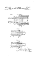
Fig. l is a sectional elevation, the lower half of which shows the parts assembled and the upper half trier the sleeve hasbeen contracted. Figs. 2, 3 and 4 are similar views of modified forms. Figs. 5 and 6 showhalf in section, two forms wherein the hose is sealed to the fitting by a grip brought about by contracting a part of the end fitting. Fig. 7 shows a way of sheathing the-sleeyeand the adjacent end of thehosebody.
Fig. 8 accompanying the present specification shows another form of couplingcomponent. Fig. 9 is a sec s rated from the projecting portion 5 of the inner resilient natural or synthetic) and a layer of reinforcing material.
3 of the kind in which ribbon-like groups of fine high tensilesteel wires are braided to tubular form. The end portion of the outer resilient layer is cut away and the end portion 4 of the reinforcing material thus externally bared, a portion 5 of the inner resilient layer projecting forwardly beyond the end of the outer layer.
The outer part of the metal end fitting comprises a member 6 providing a sleeve 7 with an end Wall 8 and an extension 9 from the end wall in a direction opposite to the sleeve. The end wall is grooved at 10 to approximately half-circular profile, forming an inner annular rearwardly extending lip 11. The sleeve is provided with an integral external band 1 2 at its end remote from the end wall. '(This band may be formed by a separate ring if desired.) 'A ring 13 is provided of circular section metal arranged so that it may be brought substantially concentric with the half-circular section groove 10.
The end portion 4 of the reinforcing material is sepalayer and is folded round the ring 13.
The projecting portion '5 of the inner layer is intended to act as a cylindrical sealing member by engaging with a seating surface 14 formed by the inner peripheral surface of the extension 9. This seating surface is stepped by means of the radiussed shoulder, 15'and the sealing member is likewise stepped and shouldered.
A spring insert 16 is introduced into the sealing mern- V berand some way into the body of the hose and it is energised was to hold the sealing member firmly against its seating when there is a low pressure or no pressure of fluid in the hose, whilst allowing the fluid to pass between the convolutions of the spring and press the sealing mernber' more firmly against its seating at high internal pressures.
The sealing surface of the sealing member is ground to a desired degree of smoothness and to enable this to be eifected, the separate end portion 4 of the reinforcing material is folded round the ring 13 and held by a suitable tool so that the grinding tool can operate on the sealing member 'over its smaller external diameter and if desired over as much of its larger diameter as possible.
It will be observed that the sealing member can be very satisfactorily exposed for grinding.
When the sealing member has been prepared and the tool removed (the stepped seating surface will have been prepared to enable sealing contact to be effectively made with it) the member 6v is forced over the sealing member and the sleeve 7 overtheflaredbared material 4, and the sleeve forced home as shown in the lower half of the figure. The swaging band 12 lies round the end portion of the .outer layer 2, the forward face of which contacts or lies close to the ring 13. The swaging band is now contracted and in closinginwards it brings the extreme portion of the bared reinforcing'material extending beyond the gripping zone into contact with the outer layer of the hose, draws the bared reinforcing material around the ring and exerts a forward thrust on the ring causing its forward surface to press the reinforcing material powerfully againstthecomplementary surface of the groove 10 to produce the said gripping zone where a powerful grip of the reinforcing material around its fold isproduceda Only a shortlength of taut reinforcing material is left under the ring between the embedded portion of such material and the gripping zone where it is strongly clamped between the ring and the surface of the groove, and the lip 11 and the ungripped reinforcing material supports the inner layer when forced out by .the internal pressure so that there is continuous support of the inner layer in a region where damage to such layer might result. It also provides support for the ring to prevent collapse.
In the form shown in Fig. 2 instead of the swaging band 12 the end 18 of the sleeve is turned or rolled in by any appropriate spinning, pressing or rolling tool.
Fig. 3 shows a modification in which the ring 13 has a rearward extension 19, the inner diameter of which is substantially that of the ring and the external diameter of which is sufiiciently less than that of the ring to en able the sleeve to close in behind the ring and exert the desired forward thrust thereon. In this form, the extreme end of the bared material extending rearwardly beyond the gripping zone between the ring and the groove, is gripped between the sleeve and the extension 19 and the said extension is contracted sulficiently to press the reinforcing material under it against the inner layer of the hose. 1
In each of the forms before described, the extension 9 of the member 6 is formed as a sealing nipple adapted rotatably to support a union nut, e. g., in the manner described and claimed in my prior Patent No. 2,310,490 but the fitting may be adapted for coupling to a companion member by screwing or any other suitable way. The nipple, screw or other means of connection need not be an integral part of the member carrying the sleeve, e. g., it may be a separate part secured as shown in Fig. 4, i. e., having a collar 20 held in position by swaging in the end portion 21 of the member 6. It may also be attached to the insert or a composite end fitting in which the insert and the outer part are integral.
Figs. 5 and 6 show the invention applied to a coupling component in which the hose is sealed by a grip brought about by contracting a portion of the outer part of the end fitting, producing thereby a seal which is efiective even at negative pressure. Referring to Fig. 5 the end portion of the inner layer projects and is externally ground before assembly of the sleeve, to act as a sealing member, but the spring is replaced by a rigid tubular insert 22 and a portion of the member 6 around the sealing member is contracted sufficiently to grip the sealing member between that portion of the member 6 and the insert and produce an efiective seal. In Fig. 6 the sealing member is left unground and the internal wall of the member 6 is ribbed or serrated at 23 and swaged inwards. The inner crests of the ribs localise the pressure on the resilient material and displace the said material sufiiciently to cause it to mould itself to the ridges and produce an efiective seal even though the initial sealing surface of the resilient material is uneven due to the reinforcing material having embedded into it before it was turned back around the ring. The crests of the ribs may be fiat or curved instead of being sharp as shown.
Fig. 5 also shows a modified cross-section of the ring in which the approximately 90 portion of the ring remote from the end wall is left with sides making 90 to one another, e. g., as it has been cut from the tube. The ring fits snugly against the end face 24.of the outer resilient layer. This feature may obviously be applied to the forms shown in Figs. 1 to 4.
The inserts shown in Figs. 5 and 6 may be and preferably are apertured to allow the internal fluid under pressure in the hose to press the sealing member more strongly on its seating.
Fig. 7 shows how a sheath 17 may be finally fitted over the member 6 to lie around the peripheral wall and against the end wall of the sleeve and around the body of the hose. The sheath may be made of rubber or other suitable material, if desired metal. The sheath may be employed to seal 05 the outer wall of the hose with the sleeve and prevent any projection of the bare reinforcing material. t may be made of a suitable fire or high temperature resisting medium. It also gives a finished appearance to the coupling component.
In Fig. 8 the forward region of said projecting portion of the inner layer is intended to provide an annular high pressure sealing member 14 adapted to be forced outwardly by internal fluid pressure within the hose into sealing contact with a seating 15 provided by the said extension, and the said extension in the region between the said seating and the said end wall 8 is contracted to grip the inner layer between the extension and an insert 16 located in the bore of the hose. The forward region aforesaid of the inner layer is made of reduced external diamv eter compared with the region between the seating and the end wall and the extension is shouldered internally and externally at 13. The sealing surface of the sealing member and the seating surface are parallel to their common axis. The insert lies within the two regions of the projecting portion of the inner layer and has a circumferential series of holes 19 where it lies within the sealing member 14. The internal periphery of the region of the extension intended to be contracted has a number of annular grooves 28.
Fig. 9 shows another form of coupling component with an end piece 28 which may be screwed to the component at any convenient time during assembly and by the aid of which the end of the component may be left open for ascertaining that the rest of the parts are correctly assembled. This form may have a spring insert and promotes the use of a more heavily loaded spring.
Fig. 10 shows a form in which the lip 11 is not integral with the end wall but is a separate ring.
The hose may have a fabric reinforcing layer instead of a metallic or fabric covered metallic layer, if one or both of the gripping faces be of a material which'will grip it Without damage, e. g., if the ring he made of brass or other metal suitably softer than the sleeve or if the recess be lined or otherwise provided with a separate ring member of appropriate material.
The sleeve need not have an enlarged swaging band, e. g., it may be of uniform wall thickness.
When it is stated that the reinforcing layer is bare, it is intended to include constructions in which there is on the layer a contiguous fabric cover or a layer of rubber so thin that when gripping takes place it is substantially entirely forced into the interstices of the reinforcing layer.
Where such fabric material is present, we prefer however to remove it so that the metal is directly gripped.
If the hose has inner and outer resilient layers, two or more reinforcing layers and one or more intervening resilient layers, preferably the inner reinforcing layer is exposed and gripped between the sleeve and the ring, the outer reinforcing layer(s) and the intervening and outer resilient layers being removed. Alternatively, the outer reinforcing layer is exposed and gripped between the sleeve and the ring, the intervening resilient layer(s) and the inner reinforcing layer(s) being removed to expose a projecting portion of the inner resilient layer to form a sealing member.
When it is stated that the outer sleeve is contracted it is meant that it is of such metal, and is subjected to such pressure that a permanent deformation is produced; suitable metals are brass, aluminum, mild steel and Phosphorbronze.
What I claim is:
l. A hose coupling component having a flexible hose with tubular layers of resihent material and tubular fienible reinforcing material embedded between them and an end fitting comprising an insert fitting into the end of the hose and an outer part including an outer sleeve having a forward end wall wherein (a) the end portion of the reinforcing material bare of the resilient material is passed through and folded back on the outside and extended rearwardly of a ring shaped and proportioned so that the bare material makes an easy fold following the forward surface of the ring, (12) the outer sleeve of the end fitting surrounds the ring and its end wall has an annular groove with an inner annular rearwardly-extending lip, which groove with the lip forms a surface complementary to the said forward surface of the ring into which groove with the lip the forward surface of the ring and the bare material folded about it intrudes, (c) the sleeve has been contracted inwardly behind the ring and as a result of said contractionand cooperation with the rearward surface of the ring has caused a forward thrust to be exerted on the ring whereby the fold of the reinforcing material is powerfully gripped between the complementary surfaces of the ring and the groove with the lip without inward contraction of the ring and (d) the resilient material of the hose any radial section at least over its forward surface so that the bare material makes an easy fold following the said forward surface of the ring, (b) the outer sleeve of theend fitting surrounds the ring and its end wall has an annular groove with an inner annular rcarWardly-extending lip, which groove with the lip forms a surface complementary to the said forward surface of the ring and into'which groove with the lip the forward surface of the ring and the bare material folded about it intrudes the inner resilient layer projecting forwardly under the lip and being held between the insert and a forward extension of said sleeve and serving as a sealing member, and (c) the outer part of the rearward surface of the ring is directed rearwardly and inwardly and the sleeve has been contracted inwardly therearound and caused a forward thrust V to be'exerted on the ring whereby the fold of the reinforcing material is powerfully gripped between the complementary surfaces of the ring and the groove with the lip w ithout inward contraction of the ring.
3. A hose coupling component according to claim 2 in which the ring is circular in cross section at any radial section at least over its forward surface behind which the sleeve has been contracted and the outer. part of its rearward surface.
4. A hose coupling component according to claim 1 in which the said rearwardly extending part of the bare material is gripped between the sleeve and the body of the hose.
5. A hose coupling component according to claim 1 in which the ring has a rearward extension suificiently less in external diameter than the external diameter of the ring to enable the desired forward thrust to be given to the ring andfthe said rearwardly extending part of the material is gripped between the sleeve and said extension which is contracted as a result of contracting the sleeve.
6. A hose coupling component according to claim 1 in which the lip is not integral with the end wall but is a gripping surfaces isof material sufficiently soft to grip it without damage. I 10. The hose coupling component according to claim "1 in which the gripping surface of the groove is formed y a lining thereof. 7 V
11. A hose coupling component according to claim'l in which the hose has an end portion of its inner resilient layer projecting beyond the outer resilient layer, said outer part of the end fitting having an extension providing an internal seating for the outer periphery of at least part of the said projecting portion of the innerresilient layer, 7
and in which there is a forward region of the insert and the forward region of the said projecting portion of the inner layer surrounding said region of the insert is adapted to be pressed intofcontact with the said seating by internal pressure and a region of said projecting portion between the forward region and the outer layer of the hose is gripped between the said extension of the end fitting and the insert by contracting the extension.
12. A hose coupling component according to claim 11 in which the said forward region of the insert is apertured.
13. A hose coupling component according to claim 1 in which the hose has an end portion'of its inner resilient I layer projecting beyond the outer resilient layer, said outer part of the end fitting providing an internal seating for the outer periphery of at least part of the said projecting portion'of the inner resilient layer, and in which at least the forward region of the insert is resilient and the forward region of the projecting portion of the inner layer surrounding said region of the insert is pressed into contact with the seating by said resilient portion and is adapted to be pressed more strongly into contact with the seating by internal fluidpr'essure and a region of said projecting portion between the forward region and the outer layer of the hose is gripped between the said outer-portion of the end fitting and the insert.
14. A hose coupling component according to claim l'in which the hose has an end portion of its inner resilient layer projecting beyond the outer resilient layer, said outer part of the end fitting having an internal seating for the outer periphery of at least part of the said projecting portion of the inner resilient layer, and in which the free end. region of the said projecting portion of the inner layer is externally reduced to a constant smaller diameter to render it more responsive to the internal pressure, the seating being appropriately formed to co-operate with the said reduced diameter region. 7
15. A hose coupling component according to claim 1 in which the hose has an end portion of its inner resilient layer projecting beyond the outer resilient layer said outer part of the end fitting having extension providing an internal gripping wall for the outer periphery of at least part of said projecting portion of the inner resilient layer, and in which the said gripping wall of the said extension is annularly ribbed so that the contraction of the extension creates high pressure regions under the rib or ribs and causes the resilient material to mould itself thereto and provide efficient s'ealing despite any irregularitieshn the surface of the resilient material before contraction.
References Cited in the file of this patent UNITED STATES PATENTS Allison V V Sept. 16, 1952
Applications Claiming Priority (1)
| Application Number | Priority Date | Filing Date | Title |
|---|---|---|---|
| GB2741496X | 1951-06-21 |
Publications (1)
| Publication Number | Publication Date |
|---|---|
| US2741496A true US2741496A (en) | 1956-04-10 |
Family
ID=10914448
Family Applications (1)
| Application Number | Title | Priority Date | Filing Date |
|---|---|---|---|
| US293762A Expired - Lifetime US2741496A (en) | 1951-06-21 | 1952-06-16 | Flexible hose coupling with anchored reinforcing layer |
Country Status (1)
| Country | Link |
|---|---|
| US (1) | US2741496A (en) |
Cited By (13)
| Publication number | Priority date | Publication date | Assignee | Title |
|---|---|---|---|---|
| US2872865A (en) * | 1955-09-29 | 1959-02-10 | Karsten S Skaar | High strength fiber glass-metal construction and process for its manufacture |
| US3109670A (en) * | 1960-10-17 | 1963-11-05 | Charles F Engel | Air duct installations |
| US3167330A (en) * | 1957-04-26 | 1965-01-26 | Donald A Draudt | Coupling |
| US3237974A (en) * | 1965-02-10 | 1966-03-01 | Resistoflex Corp | Hose fitting |
| US3368835A (en) * | 1961-08-09 | 1968-02-13 | Hackforth Bernhard | Flexible couplings |
| US4313629A (en) * | 1980-07-14 | 1982-02-02 | Champion Spark Plug Company | Hose connector |
| US4679826A (en) * | 1985-05-06 | 1987-07-14 | Flow Industries, Inc. | High pressure hose fitting |
| US6598906B2 (en) * | 2001-02-27 | 2003-07-29 | Dana Corporation | Fluid couplings |
| US20030197372A1 (en) * | 2001-02-27 | 2003-10-23 | Dana Corporation | Fluid couplings |
| US20100230952A1 (en) * | 2009-03-16 | 2010-09-16 | BPP Technical Services Ltd. | Hose End Fitting |
| US20100229995A1 (en) * | 2009-03-16 | 2010-09-16 | BPP Technical Services Ltd. | Hose |
| US20150313100A1 (en) * | 2012-06-28 | 2015-11-05 | Jain Irrigation Systems Limited | On and off tube weight for drip irrigation |
| US10247337B2 (en) * | 2017-03-20 | 2019-04-02 | Contitech Usa, Inc. | Hose end construction and fitting |
Citations (3)
| Publication number | Priority date | Publication date | Assignee | Title |
|---|---|---|---|---|
| US213577A (en) * | 1879-03-25 | Improvement in hose-couplings | ||
| US1926270A (en) * | 1932-08-13 | 1933-09-12 | Eastman Joseph Peter | Pressed-on hose coupling |
| US2610869A (en) * | 1949-03-30 | 1952-09-16 | Flight Refueling Ltd | Flexible hose end connection |
-
1952
- 1952-06-16 US US293762A patent/US2741496A/en not_active Expired - Lifetime
Patent Citations (3)
| Publication number | Priority date | Publication date | Assignee | Title |
|---|---|---|---|---|
| US213577A (en) * | 1879-03-25 | Improvement in hose-couplings | ||
| US1926270A (en) * | 1932-08-13 | 1933-09-12 | Eastman Joseph Peter | Pressed-on hose coupling |
| US2610869A (en) * | 1949-03-30 | 1952-09-16 | Flight Refueling Ltd | Flexible hose end connection |
Cited By (15)
| Publication number | Priority date | Publication date | Assignee | Title |
|---|---|---|---|---|
| US2872865A (en) * | 1955-09-29 | 1959-02-10 | Karsten S Skaar | High strength fiber glass-metal construction and process for its manufacture |
| US3167330A (en) * | 1957-04-26 | 1965-01-26 | Donald A Draudt | Coupling |
| US3109670A (en) * | 1960-10-17 | 1963-11-05 | Charles F Engel | Air duct installations |
| US3368835A (en) * | 1961-08-09 | 1968-02-13 | Hackforth Bernhard | Flexible couplings |
| US3237974A (en) * | 1965-02-10 | 1966-03-01 | Resistoflex Corp | Hose fitting |
| US4313629A (en) * | 1980-07-14 | 1982-02-02 | Champion Spark Plug Company | Hose connector |
| US4679826A (en) * | 1985-05-06 | 1987-07-14 | Flow Industries, Inc. | High pressure hose fitting |
| US6598906B2 (en) * | 2001-02-27 | 2003-07-29 | Dana Corporation | Fluid couplings |
| US20030197372A1 (en) * | 2001-02-27 | 2003-10-23 | Dana Corporation | Fluid couplings |
| US7178836B2 (en) | 2001-02-27 | 2007-02-20 | Dana Corporation | Fluid couplings |
| US20100230952A1 (en) * | 2009-03-16 | 2010-09-16 | BPP Technical Services Ltd. | Hose End Fitting |
| US20100229995A1 (en) * | 2009-03-16 | 2010-09-16 | BPP Technical Services Ltd. | Hose |
| US20150313100A1 (en) * | 2012-06-28 | 2015-11-05 | Jain Irrigation Systems Limited | On and off tube weight for drip irrigation |
| US10342187B2 (en) * | 2012-06-28 | 2019-07-09 | Jain Irrigation Systems Limited | On and off tube weight for drip irrigation |
| US10247337B2 (en) * | 2017-03-20 | 2019-04-02 | Contitech Usa, Inc. | Hose end construction and fitting |
Similar Documents
| Publication | Publication Date | Title |
|---|---|---|
| US2741496A (en) | Flexible hose coupling with anchored reinforcing layer | |
| US3423109A (en) | Hose fitting | |
| US2797111A (en) | Fitting for plural layer wire reinforced hoses | |
| US2809056A (en) | Plural layer hose fitting having wedge gripping means for the plural layers | |
| US2848254A (en) | End fittings for flexible metallic hose | |
| US2940778A (en) | Fitting for a large-diameter rubber or plastic hose subjected to high loads | |
| US3224794A (en) | High pressure hose fitting | |
| US3140106A (en) | Lip seal case fitting | |
| US2833567A (en) | Fitting for reinforced hose with seal maintaining means | |
| US3233907A (en) | Coupling for joining pipe sections of differing diameter | |
| US2926029A (en) | Hose coupling having upset locking means | |
| US3008736A (en) | High pressure flexible hose coupling | |
| US2383733A (en) | Tube structure | |
| US1825005A (en) | Means for attaching fittings to the ends of high pressure hose | |
| US2865094A (en) | Method of securing a coupling to an end of a high temperature flexible hose | |
| US2028316A (en) | Hose fitting | |
| US1901088A (en) | Method of making hose connections | |
| US1928836A (en) | Hose coupler | |
| US2550583A (en) | Flexible hose coupling | |
| US1969203A (en) | Hose coupling and method of making the same | |
| US2797474A (en) | Method of applying hose fittings | |
| US2298736A (en) | Flanged hose | |
| US2219266A (en) | Hose and pipe coupling | |
| US2753196A (en) | Coupling for flexible plural layer hose | |
| US2733940A (en) | millar |