US2740684A - Filing cabinet - Google Patents
Filing cabinet Download PDFInfo
- Publication number
- US2740684A US2740684A US387145A US38714553A US2740684A US 2740684 A US2740684 A US 2740684A US 387145 A US387145 A US 387145A US 38714553 A US38714553 A US 38714553A US 2740684 A US2740684 A US 2740684A
- Authority
- US
- United States
- Prior art keywords
- door
- assembly
- filing cabinet
- casing
- plunger
- Prior art date
- Legal status (The legal status is an assumption and is not a legal conclusion. Google has not performed a legal analysis and makes no representation as to the accuracy of the status listed.)
- Expired - Lifetime
Links
Images


Classifications
-
- A—HUMAN NECESSITIES
- A47—FURNITURE; DOMESTIC ARTICLES OR APPLIANCES; COFFEE MILLS; SPICE MILLS; SUCTION CLEANERS IN GENERAL
- A47B—TABLES; DESKS; OFFICE FURNITURE; CABINETS; DRAWERS; GENERAL DETAILS OF FURNITURE
- A47B49/00—Revolving cabinets or racks; Cabinets or racks with revolving parts
- A47B49/004—Cabinets with compartments provided with trays revolving on a vertical axis
Definitions
- a primary object of this invention is to provide an improved filing cabinet wherein articles are compactly stored and wherein means are provided for rapidly locating and rendering such articles accessible.
- Another object of this invention is to provide means including a color coating system taken in conjunction with a series of numbered ledges functionally related to control mechanism for a filing cabinet wherein the articles disposed therein may be rapidly and easily located and obtained.
- Another object of this invention is to provide an improved form of filing cabinet in conformity with the foregoing object wherein the locating mechanism includes a series of lights.
- Another object of this invention is to provide an improved form of filing cabinet which incorporates an automatically operated door mechanism and release mechanism therefor functionally related to the control mechanism for the locating device of the cabinet.
- Still another object of this invention is to provide an improved form of filing cabinet in conformity with the foregoing objects wherein the electrical circuit containing the light is normally rendered inoperative but is energized in response to opening of the cabinet door.
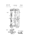
- Figure 1 is a perspective view of the filing cabinet structure
- Figure 2 is a view similar to Figure 1 but showing the cabinet with its door open;
- Figure 3 is a top plan view of the assembly shown in Figures 1 and 2;
- Figure 4 is an enlarged horizontal section taken substantially along the plane of section line 4-4 of Figure 1 and showing details of the control mechanism;
- Figure 5 is an enlarged vertical section taken substantially along the plane of section line 5-5 in Figure 2 showing details of the internal construction of the cabinet assembly;
- Figure 6 is an enlarged elevational view taken substantially along the plane of section line 6-6 in Figure 5 showing details of the latch and latch release mechanism;
- Figure 7 is another enlarged vertical section taken through the assembly along the plane of section line 7-7 in Figure 3;
- Figure 8 is a diagrammatic view showing the control circuit for the electrical system of the filing cabinet
- Figure 9 is a perspective view showing the door opening mechanism
- Figure 10 is an enlarged vertical section taken through the selector mechanism and showing the door release mechanism mounted thereon;
- Figure 11 is a perspective view of the carrier assembly
- Figure 12 is a horizontal section taken substantially along the plane of section line 12-12 in Figure 5 showing details of the lock mechanism
- Figure 13 is an enlarged partial plan view showing a portion of the top of the cabinet assembly.
- reference numeral 10 indicates the filing cabinet assembly generally which includes, in a preferred embodiment of the device, a series of vertically arranged upright members 12 having their lower ends interconnected by the cross-piece members 14 in the manner shown most clearly in Figures 1 and 2 and a series of panels 16 are disposed between these uprights with the exception of one pair of the same wherein an opening is provided in the casing or housing assembly defined by these members.
- a suitable bottom 18 is provided for the assembly, this bottom being secured at its peripheral edge to the previously mentioned panels 16 and being provided between the said pair of uprights between which the opening is provided with a flange member 20 to enhance the appearance of the device all as best shown in Figure 5.
- a suitable top member 22 is provided and secured much in the same manner as the bottom 18 and this member is also provided with a flange portion 24 corresponding to the previously mentioned flange member 20.
- a pair of suitable bearing bosses 26 and 28 are provided on the bottom and top members respectively for rotatably receiving a pivot shaft 30 therein (see Figure 4), which pivot shaft is frictionally received within the vertical sleeve 32 in the carrier assembly which is indicated generally by the reference character 34 and is shown most clearly in Figure 11.
- This sleeve as best shown in Figure 11, is provided with a series of radially extending plate members 36 and segmental shelf members 38 are secured between these plate members to form a series of vertically arranged and spaced shelf assemblies 40, 42, 44, 46 and 48, it being readily apparent that any desired number of shelves may be utilized.
- each compartment may be identified with a number imprinted on the retaining flange and extending within each shelf structure counterclockwise therearound and additionally such that the lowest number of each shelf assembly is disposed in vertical alignment with the lowest number of the other shelf assemblies as shown in Figure 11. The purpose of this construction will be presently apparent.
- the gear member 54 (see Figures 4 and 5) is suitably feathered to the upper end of the pivot shaft 30 and the pinion 56 is meshed therewith, this pinion being carried by a stub shaft 58 (see Figure 2) extending through the top member 22 and provided at its upper end with a control knob member 60 wherein the pinion 56 and consequently the gear 54 and shaft 30 may be rotated at the discretion of the user.
- the other end of the pivot shaft 30 is provided with suitable markings 62, 64, 66 and 68 (see Figure 13) each of which is provided with a different color and each of which is selectively registerable with an indicator or pointer 70 on the bearing boss member 28, it being appreciated that each position of one of the various indicia 62-68 corresponds to a position on the carrier within the casing assembly wherein one series of vertically arranged shelf compartments is in registry with the opening in that casing.
- suitable markings 62, 64, 66 and 68 each of which is provided with a different color and each of which is selectively registerable with an indicator or pointer 70 on the bearing boss member 28, it being appreciated that each position of one of the various indicia 62-68 corresponds to a position on the carrier within the casing assembly wherein one series of vertically arranged shelf compartments is in registry with the opening in that casing.
- a switch shaft 72 (see Figures 4 and 13) is journaled in the top member 22 and is provided exteriorly thereof with a control knob 74 including a pointer 76 to indicate one of the several positions as indicated by the various indicia 78, 80, 82, 84 and 86.
- These indicia correspond respectively to the various legends indicated generally by the reference characters 88, 90, 92, 94 and 96.
- These various indicia and their corresponding legends correspond to the several positions of the switch wherein the movable contact finger 98 thereof (see Figure 4) is selectively engageable with the various stationary contacts 100 disposed radially of and in circumferentially spaced relation with the switch shaft 72.
- the movable contact 98 (see Figure 8) is provided with a brush member 102 connected to a power input line 104 and the several lines 106 extending from the various stationary contacts are connected to the indicator light 108 secured to the casing assembly adjacent its opening with one of each light in alignment for illuminating one of the compartments in registry with the opening of the casing.
- this provides a rapid and convenient means for locating articles that are desired.
- top and bottom members 18 and 22 are provided with rail members 110 (see Figure 7) of similar circular configuration and an arcuate door member 112 best shown in Figure 9, is provided at its top and bottom edges respectively with groove and roller members 114 engaging these rails such that the door is slidable between open and closed positions.
- a handle member 116 is provided on the door in aiding in closing the same and the door rigidly carries a notch latch bar 118 which is projectible through an opening 120 in a keeper member 122 (see Figures 6 and 12) rigidly secured to the casing member, the notch 124 in the bar 118 being engageable by the lower end of a plunger member 126.
- the plunger 126 is normally in the lower position as shown in Figure 6 and as the door is closed the cam portion 128 of the latching bar lifts this plunger member upwardly to allow the same to fall into the notch 124 and latch the door in closed position.
- the switch assembly indicated generally by the reference character 130 is opened by engagement of the free end portion of the latching bar with an insulated block 132 on the movable contact 134 to disengage this contact with the stationary contact 136.
- One side of the switch, as shown in Figure 8, is connected to the previously mentioned lines 104 and the other contact, or stationary contact 136, is connected to the main lead line 138 extending to the transformer assembly 140 which may be provided for operating the light 108 on reduced voltage from an ordinary household outlet line.
- the other line 142 extending from the transformer extends to the various lights 108 which are connected in parallel therewith.
- the plunger 126 is provided with pin members 144 engageable by the spaced ear members 146 on the locking arm 148 which is pivotally connected as by a member 150 to a lock barrel in the key lock assembly indicated generally by the reference character 152, it being manifest operation of the key lock is such that normally when the key is out of position therein the arm 148 is prevented from pivotal movement such that the lower end of the plunger 126 may not be disengaged from the notch 124. Conversely, when the key is inserted in the lock, the arm 148 is permitted to move when the plunger 126 is actuated as hereinafter described to release the latching of the door.
- the side edge of the door opposite the latch bar 118 is provided with a cam bar 154 having a lower cam edge 156 and a flexible element 158 is connected at one end to this edge of the door and extends therefrom over the various pulleys, 160,
- a retarding arm 168 is pivotally secured in an intermediate portion as by a pin member 170 to the casing and the upper end of this arm is provided with a laterally bent ear 172 which falls in the path of movement of the cam edge 156 of the cam plate or bar 154 and the lower end of the arm is attached to a tension spring 174 such as the arm is normally disposed in a vertical position.
- the cam edge .56 strikes the upper end ear 152 of the arm and rotates the same in opposition to the spring 174 which retards the final opening motion of the door, preventing the violent stopping of the door at the ends of its opening.
- the bell crank member 176 is pivoted to the undersurface of the top member 22 as by the bracket ears 178 and associated pin 180.
- One end of this crank is disposed beneath the lower end of the stub shaft 58, the stub shaft being hollow or provided with a longitudinal bore for reciprocably receiving an actuating plunger 182 provided at its upper end with a push button member 184 reciprocably received within a recess in the upper surface of the knob 60, a spring member 186 being provided for normally urging the actuating plunger 182 to the position as shown in Figure 10.
- any of the various compartments in the several shelf assemblies may be instantly located by proper manipulation of the control. This is accomplished by first locating the article desired to be obtained on one of the various legends 8896.
- Each legend contains a number of articles corresponding to the number of compartments in each shelf assembly and each of the number blocks 204 in the various legends is provided with a suitable color corresponding to the colors of the various indicia 6268.
- Each number block and each of the legends is differently colored and the colors of the number blocks corresponding to the numbers 1, 5, 9, 13 and 17 are provided with the same color as are the numbers 2, 6, 10, 14 and 18 and so forth over the entire range of the articles numbered.
- the switch knob 74 is then rotated such that the pointer 76 is on one of the various corresponding indicia 78- 86 and the control knob 60 is then manipulated to rotate the carrier to a position wherein one of the indicia 62-68 corresponds to the color of the article desired.
- the push button is then manipulated and the door will open to complete the circuit to the proper indicating lamp which will illuminate that compartment containing the desired article so that the article may be readily and quickly obtained.
- a filing cabinet comprising a casing, said casing having an opening, a carrier rotatably mounted in said casing, said carrier including a plurality of vertically spaced shelves, each divided into a plurality of compart ments, a series of vertically spaced lights disposed within said casing adjacent its opening for illuminating individual ones of the vertically arranged shelves, an electrical circuit for said lights including a rotary switch selectively controlling energization of any one of the lights.
- each legend comprising a list of articles disposed in the separate compartments of :1 corresponding shelf and an identifying color for each separate article, said compartments being in vertical alignment and the identifying color in the several legends being the same for nil articles disposed in each vertical row of compartments,
- the last-mentioned means including a color-coded knob and an indicator on the casing for determining the positioning of the carrier to correspond to an article selected.
Landscapes
- Casings For Electric Apparatus (AREA)
Description
April 3, 1956 J. 5. HARALSON 2,740,684
FILING CABINET Filed Oct. 20, 1953 5 Sheets-Sheet 1 Fig./ Fig.2
74 5 60 55 @60 22 22 v D E fl Jesse .S. Ham/son 1N VEN TOR.
April 1956 J. s. HARALSON 2,740,684
FILING CABINET Filed Oct. 20, 1953 5 Sheets-Sheet 2 Fig.5
Jesse S. Hora/son I N V EN TOR.
BY WM! mg;
April 3, 1956 Filed Oct. 20, 1953 J. S. HARALSON FILING CABINET Fig. 8
5 Sheets-Sheet 4 Jesse S. Hora/son INVENTOR.
United States Patent FILING CABINET Jesse S. Haralson, Cincinnati, Ohio Application October 20, 1953, Serial No. 387,145 2 Claims. (Cl. 312-223) This invention relates generally to articles of furniture and pertains more particularly to an improved cabinet construction.
A primary object of this invention is to provide an improved filing cabinet wherein articles are compactly stored and wherein means are provided for rapidly locating and rendering such articles accessible.
Another object of this invention is to provide means including a color coating system taken in conjunction with a series of numbered ledges functionally related to control mechanism for a filing cabinet wherein the articles disposed therein may be rapidly and easily located and obtained.
Another object of this invention is to provide an improved form of filing cabinet in conformity with the foregoing object wherein the locating mechanism includes a series of lights.
Another object of this invention is to provide an improved form of filing cabinet which incorporates an automatically operated door mechanism and release mechanism therefor functionally related to the control mechanism for the locating device of the cabinet.
Still another object of this invention is to provide an improved form of filing cabinet in conformity with the foregoing objects wherein the electrical circuit containing the light is normally rendered inoperative but is energized in response to opening of the cabinet door.
These together with other objects and advantages which will become subsequently apparent reside in the details of construction and operation as more fully hereinafter described and claimed, reference being had to the accompanying drawings forming a part hereof, wherein like numerals refer to like parts throughout, and in which:
Figure 1 is a perspective view of the filing cabinet structure;
Figure 2 is a view similar to Figure 1 but showing the cabinet with its door open;
Figure 3 is a top plan view of the assembly shown in Figures 1 and 2;
Figure 4 is an enlarged horizontal section taken substantially along the plane of section line 4-4 of Figure 1 and showing details of the control mechanism;
Figure 5 is an enlarged vertical section taken substantially along the plane of section line 5-5 in Figure 2 showing details of the internal construction of the cabinet assembly;
Figure 6 is an enlarged elevational view taken substantially along the plane of section line 6-6 in Figure 5 showing details of the latch and latch release mechanism;
Figure 7 is another enlarged vertical section taken through the assembly along the plane of section line 7-7 in Figure 3;
Figure 8 is a diagrammatic view showing the control circuit for the electrical system of the filing cabinet;
ICC
Figure 9 is a perspective view showing the door opening mechanism;
Figure 10 is an enlarged vertical section taken through the selector mechanism and showing the door release mechanism mounted thereon;
Figure 11 is a perspective view of the carrier assembly;
Figure 12 is a horizontal section taken substantially along the plane of section line 12-12 in Figure 5 showing details of the lock mechanism; and
Figure 13 is an enlarged partial plan view showing a portion of the top of the cabinet assembly.
Referring now more particularly to the drawings, reference numeral 10 indicates the filing cabinet assembly generally which includes, in a preferred embodiment of the device, a series of vertically arranged upright members 12 having their lower ends interconnected by the cross-piece members 14 in the manner shown most clearly in Figures 1 and 2 and a series of panels 16 are disposed between these uprights with the exception of one pair of the same wherein an opening is provided in the casing or housing assembly defined by these members. A suitable bottom 18 is provided for the assembly, this bottom being secured at its peripheral edge to the previously mentioned panels 16 and being provided between the said pair of uprights between which the opening is provided with a flange member 20 to enhance the appearance of the device all as best shown in Figure 5. Likewise, a suitable top member 22 is provided and secured much in the same manner as the bottom 18 and this member is also provided with a flange portion 24 corresponding to the previously mentioned flange member 20.
A pair of suitable bearing bosses 26 and 28 (see Figure 5) are provided on the bottom and top members respectively for rotatably receiving a pivot shaft 30 therein (see Figure 4), which pivot shaft is frictionally received within the vertical sleeve 32 in the carrier assembly which is indicated generally by the reference character 34 and is shown most clearly in Figure 11. This sleeve, as best shown in Figure 11, is provided with a series of radially extending plate members 36 and segmental shelf members 38 are secured between these plate members to form a series of vertically arranged and spaced shelf assemblies 40, 42, 44, 46 and 48, it being readily apparent that any desired number of shelves may be utilized. To retain various articles within the several compartments formed in each shelf structure, the transparent peripheral retaining flange 50 secured to the shelf members and by a binding strip 52 which may be provided. Additionally, each compartment may be identified with a number imprinted on the retaining flange and extending within each shelf structure counterclockwise therearound and additionally such that the lowest number of each shelf assembly is disposed in vertical alignment with the lowest number of the other shelf assemblies as shown in Figure 11. The purpose of this construction will be presently apparent.
The gear member 54 (see Figures 4 and 5) is suitably feathered to the upper end of the pivot shaft 30 and the pinion 56 is meshed therewith, this pinion being carried by a stub shaft 58 (see Figure 2) extending through the top member 22 and provided at its upper end with a control knob member 60 wherein the pinion 56 and consequently the gear 54 and shaft 30 may be rotated at the discretion of the user. The other end of the pivot shaft 30 is provided with suitable markings 62, 64, 66 and 68 (see Figure 13) each of which is provided with a different color and each of which is selectively registerable with an indicator or pointer 70 on the bearing boss member 28, it being appreciated that each position of one of the various indicia 62-68 corresponds to a position on the carrier within the casing assembly wherein one series of vertically arranged shelf compartments is in registry with the opening in that casing. The purpose of this construction will be presently apparent.
A switch shaft 72 (see Figures 4 and 13) is journaled in the top member 22 and is provided exteriorly thereof with a control knob 74 including a pointer 76 to indicate one of the several positions as indicated by the various indicia 78, 80, 82, 84 and 86. These indicia correspond respectively to the various legends indicated generally by the reference characters 88, 90, 92, 94 and 96. These various indicia and their corresponding legends correspond to the several positions of the switch wherein the movable contact finger 98 thereof (see Figure 4) is selectively engageable with the various stationary contacts 100 disposed radially of and in circumferentially spaced relation with the switch shaft 72. The movable contact 98 (see Figure 8) is provided with a brush member 102 connected to a power input line 104 and the several lines 106 extending from the various stationary contacts are connected to the indicator light 108 secured to the casing assembly adjacent its opening with one of each light in alignment for illuminating one of the compartments in registry with the opening of the casing. As will be presently apparent, this provides a rapid and convenient means for locating articles that are desired.
The top and bottom members 18 and 22 are provided with rail members 110 (see Figure 7) of similar circular configuration and an arcuate door member 112 best shown in Figure 9, is provided at its top and bottom edges respectively with groove and roller members 114 engaging these rails such that the door is slidable between open and closed positions. A handle member 116 is provided on the door in aiding in closing the same and the door rigidly carries a notch latch bar 118 which is projectible through an opening 120 in a keeper member 122 (see Figures 6 and 12) rigidly secured to the casing member, the notch 124 in the bar 118 being engageable by the lower end of a plunger member 126. The plunger 126 is normally in the lower position as shown in Figure 6 and as the door is closed the cam portion 128 of the latching bar lifts this plunger member upwardly to allow the same to fall into the notch 124 and latch the door in closed position. When in closed position, the switch assembly indicated generally by the reference character 130 is opened by engagement of the free end portion of the latching bar with an insulated block 132 on the movable contact 134 to disengage this contact with the stationary contact 136. One side of the switch, as shown in Figure 8, is connected to the previously mentioned lines 104 and the other contact, or stationary contact 136, is connected to the main lead line 138 extending to the transformer assembly 140 which may be provided for operating the light 108 on reduced voltage from an ordinary household outlet line. The other line 142 extending from the transformer extends to the various lights 108 which are connected in parallel therewith.
The plunger 126, as best shown in Figure 6, is provided with pin members 144 engageable by the spaced ear members 146 on the locking arm 148 which is pivotally connected as by a member 150 to a lock barrel in the key lock assembly indicated generally by the reference character 152, it being manifest operation of the key lock is such that normally when the key is out of position therein the arm 148 is prevented from pivotal movement such that the lower end of the plunger 126 may not be disengaged from the notch 124. Conversely, when the key is inserted in the lock, the arm 148 is permitted to move when the plunger 126 is actuated as hereinafter described to release the latching of the door.
As seen most clearly in Figure 9, the side edge of the door opposite the latch bar 118 is provided with a cam bar 154 having a lower cam edge 156 and a flexible element 158 is connected at one end to this edge of the door and extends therefrom over the various pulleys, 160,
162 and 164 for securement to a weight member 166 in such manner that the door is normally urged to an open position and must be latched to remain in the closed position. The cam plate 154 is of arcuate configuration and the flexible elements extend therearound when the door is in the closed position such that this flexible element will not be drawn against the carrier assembly previously described. A retarding arm 168, see Figure 5, is pivotally secured in an intermediate portion as by a pin member 170 to the casing and the upper end of this arm is provided with a laterally bent ear 172 which falls in the path of movement of the cam edge 156 of the cam plate or bar 154 and the lower end of the arm is attached to a tension spring 174 such as the arm is normally disposed in a vertical position. As the door is moved to an open position under action of the weight member 166, the cam edge .56 strikes the upper end ear 152 of the arm and rotates the same in opposition to the spring 174 which retards the final opening motion of the door, preventing the violent stopping of the door at the ends of its opening.
In order to conveniently control the latching plunger 126, the bell crank member 176, see Figures 5 and 10, is pivoted to the undersurface of the top member 22 as by the bracket ears 178 and associated pin 180. One end of this crank is disposed beneath the lower end of the stub shaft 58, the stub shaft being hollow or provided with a longitudinal bore for reciprocably receiving an actuating plunger 182 provided at its upper end with a push button member 184 reciprocably received within a recess in the upper surface of the knob 60, a spring member 186 being provided for normally urging the actuating plunger 182 to the position as shown in Figure 10. It will be obvious that depression of the push button 184 against said end of the bellcrank 176 will effect pivoting of the bell crank 176 so that its opposite end portion which is of L-shaped configuration 188 moves the lateral ear 190 that extends beneath a collar member 192 on the plunger so that the bellcrank 176 will lift the plunger upwardly against the operation of the spring 194 normally maintaining the plunger in the lowered position. The collar 192 need not be rigidly secured to the plunger 126 but may be resiliently connected thereto as through a spring mechanism 196 and collar 198 engaging in the abutment pin 200. The spring 194 of course engages against an ear 202 on a bracket secured to the casing.
By utilizing the previously described novel actuating and operating means for the assembly, it is to be noted that any of the various compartments in the several shelf assemblies may be instantly located by proper manipulation of the control. This is accomplished by first locating the article desired to be obtained on one of the various legends 8896. Each legend contains a number of articles corresponding to the number of compartments in each shelf assembly and each of the number blocks 204 in the various legends is provided with a suitable color corresponding to the colors of the various indicia 6268. Each number block and each of the legends is differently colored and the colors of the number blocks corresponding to the numbers 1, 5, 9, 13 and 17 are provided with the same color as are the numbers 2, 6, 10, 14 and 18 and so forth over the entire range of the articles numbered. The switch knob 74 is then rotated such that the pointer 76 is on one of the various corresponding indicia 78- 86 and the control knob 60 is then manipulated to rotate the carrier to a position wherein one of the indicia 62-68 corresponds to the color of the article desired. The push button is then manipulated and the door will open to complete the circuit to the proper indicating lamp which will illuminate that compartment containing the desired article so that the article may be readily and quickly obtained.
From the foregoing, the construction and operation of the device will be readily understood and further explanation is believed to be unnecessary. However, since numerous modifications and changes will readily occur to those skilled in the art, it is not desired to limit the invention to the exact construction shown and described, and accordingly, all suitable modifications and equivalents may be resorted to, falling within the scope of the appended claims.
What is claimed as new is as follows:
1. A filing cabinet comprising a casing, said casing having an opening, a carrier rotatably mounted in said casing, said carrier including a plurality of vertically spaced shelves, each divided into a plurality of compart ments, a series of vertically spaced lights disposed within said casing adjacent its opening for illuminating individual ones of the vertically arranged shelves, an electrical circuit for said lights including a rotary switch selectively controlling energization of any one of the lights. a series of legends corresponding to the selected positions of said switch, each legend comprising a list of articles disposed in the separate compartments of :1 corresponding shelf and an identifying color for each separate article, said compartments being in vertical alignment and the identifying color in the several legends being the same for nil articles disposed in each vertical row of compartments,
and means for rotating said carrier to selected positions for aligning a selected row of compartments at the opening in the casing, the last-mentioned means including a color-coded knob and an indicator on the casing for determining the positioning of the carrier to correspond to an article selected.
2. The combination of claim 1 wherein a door is provided for said opening, a door switch actuated in response to opening of said door for energizing said electrical Cll'Cllll'.
References Cited in the file of this patent UNITED STATES PATENTS 1,295,232 Stewart Feb. 25, 1919 1.336.500 Hile Aug. 2, 1921 $526.8 Boye Feb. 17, 1925 1,575,988 Gleerup-Moller Mar. 9, i926 2.l45,599 Haumann Jan. 31, 1939 2,617,055 Reinheimer et al. Nov. 4, 1952 2,624,650 Perales Jan. 6, 1953
Priority Applications (1)
| Application Number | Priority Date | Filing Date | Title |
|---|---|---|---|
| US387145A US2740684A (en) | 1953-10-20 | 1953-10-20 | Filing cabinet |
Applications Claiming Priority (1)
| Application Number | Priority Date | Filing Date | Title |
|---|---|---|---|
| US387145A US2740684A (en) | 1953-10-20 | 1953-10-20 | Filing cabinet |
Publications (1)
| Publication Number | Publication Date |
|---|---|
| US2740684A true US2740684A (en) | 1956-04-03 |
Family
ID=23528663
Family Applications (1)
| Application Number | Title | Priority Date | Filing Date |
|---|---|---|---|
| US387145A Expired - Lifetime US2740684A (en) | 1953-10-20 | 1953-10-20 | Filing cabinet |
Country Status (1)
| Country | Link |
|---|---|
| US (1) | US2740684A (en) |
Cited By (14)
| Publication number | Priority date | Publication date | Assignee | Title |
|---|---|---|---|---|
| US2890061A (en) * | 1956-12-03 | 1959-06-09 | Melvin R Watson | Golf club container and cart |
| WO1983000609A1 (en) * | 1981-08-14 | 1983-03-03 | Hastings, Otis, H. | Improved data processing equipment enclosures |
| US4392628A (en) * | 1981-07-21 | 1983-07-12 | Hadfield Frederick C | Concealed access furniture |
| US4449764A (en) * | 1975-08-07 | 1984-05-22 | Transaction Security, Inc. | Data processing equipment enclosures |
| US4589712A (en) * | 1977-08-25 | 1986-05-20 | Hastings Otis | Data processing equipment enclosures |
| US5860715A (en) * | 1997-03-14 | 1999-01-19 | The Toro Company | Equipment enclosure |
| US20040002287A1 (en) * | 2002-05-29 | 2004-01-01 | Anna Pedoto | Work and play station |
| US20040055913A1 (en) * | 2002-09-24 | 2004-03-25 | Adrian Berry | Casing for an electric appliance and an electric appliance with such a casing |
| US20080156749A1 (en) * | 2006-12-20 | 2008-07-03 | Thomas Shea | Free-standing, point-of-purchase display |
| USD654727S1 (en) | 2011-03-01 | 2012-02-28 | T.M. Shea Products, Inc. | Stand-alone merchandising display |
| US9320366B1 (en) * | 2013-09-03 | 2016-04-26 | Spanx, Inc. | Product storage unit and method of arrangement |
| USD793129S1 (en) * | 2013-09-03 | 2017-08-01 | Spanx, Inc. | Display tower |
| US20240306814A1 (en) * | 2023-03-17 | 2024-09-19 | A&C Future, Inc. | Three-in-one rotatable kitchen set |
| US20250338955A1 (en) * | 2024-05-03 | 2025-11-06 | Libation Aficionado, Llc. | Sample randomizer for blind testing |
Citations (7)
| Publication number | Priority date | Publication date | Assignee | Title |
|---|---|---|---|---|
| US1295232A (en) * | 1917-06-13 | 1919-02-25 | Donald Stewart | Cabinet. |
| US1386500A (en) * | 1920-06-08 | 1921-08-02 | H G Bell | Cabinet |
| US1526829A (en) * | 1923-03-19 | 1925-02-17 | Boye Needle Co | Commodity cabinet |
| US1575988A (en) * | 1924-03-29 | 1926-03-09 | Gleerup-Moller Christian | Advertising apparatus |
| US2145599A (en) * | 1937-05-13 | 1939-01-31 | Haumann George | Display device |
| US2617055A (en) * | 1949-01-18 | 1952-11-04 | Emma C Reinheimer | Filing cabinet |
| US2624650A (en) * | 1950-02-27 | 1953-01-06 | Perales Marta Perez De | File cabinet |
-
1953
- 1953-10-20 US US387145A patent/US2740684A/en not_active Expired - Lifetime
Patent Citations (7)
| Publication number | Priority date | Publication date | Assignee | Title |
|---|---|---|---|---|
| US1295232A (en) * | 1917-06-13 | 1919-02-25 | Donald Stewart | Cabinet. |
| US1386500A (en) * | 1920-06-08 | 1921-08-02 | H G Bell | Cabinet |
| US1526829A (en) * | 1923-03-19 | 1925-02-17 | Boye Needle Co | Commodity cabinet |
| US1575988A (en) * | 1924-03-29 | 1926-03-09 | Gleerup-Moller Christian | Advertising apparatus |
| US2145599A (en) * | 1937-05-13 | 1939-01-31 | Haumann George | Display device |
| US2617055A (en) * | 1949-01-18 | 1952-11-04 | Emma C Reinheimer | Filing cabinet |
| US2624650A (en) * | 1950-02-27 | 1953-01-06 | Perales Marta Perez De | File cabinet |
Cited By (16)
| Publication number | Priority date | Publication date | Assignee | Title |
|---|---|---|---|---|
| US2890061A (en) * | 1956-12-03 | 1959-06-09 | Melvin R Watson | Golf club container and cart |
| US4449764A (en) * | 1975-08-07 | 1984-05-22 | Transaction Security, Inc. | Data processing equipment enclosures |
| US4589712A (en) * | 1977-08-25 | 1986-05-20 | Hastings Otis | Data processing equipment enclosures |
| US4392628A (en) * | 1981-07-21 | 1983-07-12 | Hadfield Frederick C | Concealed access furniture |
| WO1983000609A1 (en) * | 1981-08-14 | 1983-03-03 | Hastings, Otis, H. | Improved data processing equipment enclosures |
| US5860715A (en) * | 1997-03-14 | 1999-01-19 | The Toro Company | Equipment enclosure |
| US7056183B2 (en) * | 2002-05-29 | 2006-06-06 | Umberto Ambrosini S.R.L. | Work and play station |
| US20040002287A1 (en) * | 2002-05-29 | 2004-01-01 | Anna Pedoto | Work and play station |
| US20040055913A1 (en) * | 2002-09-24 | 2004-03-25 | Adrian Berry | Casing for an electric appliance and an electric appliance with such a casing |
| US20080156749A1 (en) * | 2006-12-20 | 2008-07-03 | Thomas Shea | Free-standing, point-of-purchase display |
| US8342343B2 (en) * | 2006-12-20 | 2013-01-01 | T. M. Shea Products, Inc. | Free-standing, point-of-purchase display |
| USD654727S1 (en) | 2011-03-01 | 2012-02-28 | T.M. Shea Products, Inc. | Stand-alone merchandising display |
| US9320366B1 (en) * | 2013-09-03 | 2016-04-26 | Spanx, Inc. | Product storage unit and method of arrangement |
| USD793129S1 (en) * | 2013-09-03 | 2017-08-01 | Spanx, Inc. | Display tower |
| US20240306814A1 (en) * | 2023-03-17 | 2024-09-19 | A&C Future, Inc. | Three-in-one rotatable kitchen set |
| US20250338955A1 (en) * | 2024-05-03 | 2025-11-06 | Libation Aficionado, Llc. | Sample randomizer for blind testing |
Similar Documents
| Publication | Publication Date | Title |
|---|---|---|
| US2740684A (en) | Filing cabinet | |
| US2187012A (en) | Light-controlled actuating device | |
| US5584563A (en) | Appliance control assembly | |
| US3979017A (en) | Article dispensing apparatus | |
| US2093293A (en) | Game apparatus | |
| US2526495A (en) | Grip testing device | |
| ES349794A1 (en) | Electrical interlock circuit for multiple choice vending machines | |
| US2282164A (en) | Selective apparatus | |
| US2536544A (en) | Loose-leaf memorandum index | |
| US4170950A (en) | Sewing machine with pattern selection indicator | |
| US1987695A (en) | Game apparatus | |
| US2077684A (en) | Control device for games | |
| US2208009A (en) | Down indicator | |
| US3868112A (en) | Electrical game | |
| US3752546A (en) | Selective dispensing apparatus having door interlock structure | |
| US2614162A (en) | Currency denomination indicator | |
| US2012502A (en) | Amusement apparatus | |
| US2045061A (en) | Stove or range | |
| US2342019A (en) | Amusement apparatus | |
| US1170480A (en) | Cash-register. | |
| US3816949A (en) | Vertical index device | |
| US1982236A (en) | Vending machine | |
| US2586121A (en) | Electrically actuated target game device | |
| US2229920A (en) | Keyboard operated radio apparatus | |
| US1722342A (en) | Restaurant system |