US2732433A - Automatic telephone exchanges - Google Patents
Automatic telephone exchanges Download PDFInfo
- Publication number
- US2732433A US2732433A US2732433DA US2732433A US 2732433 A US2732433 A US 2732433A US 2732433D A US2732433D A US 2732433DA US 2732433 A US2732433 A US 2732433A
- Authority
- US
- United States
- Prior art keywords
- pulses
- switching devices
- selector switching
- terminals
- uniselector
- Prior art date
- Legal status (The legal status is an assumption and is not a legal conclusion. Google has not performed a legal analysis and makes no representation as to the accuracy of the status listed.)
- Expired - Lifetime
Links
Images

Classifications
-
- H—ELECTRICITY
- H04—ELECTRIC COMMUNICATION TECHNIQUE
- H04Q—SELECTING
- H04Q3/00—Selecting arrangements
- H04Q3/42—Circuit arrangements for indirect selecting controlled by common circuits, e.g. register controller, marker
Definitions
- the present invention relates to coding devices suitable for use in an automatic exchange as described in the specification of said co-pending U. S. patent applica tion, Serial No. 247,072.
- a plurality of communication channels are provided, and in responseto a calling signal from a calling subscriber a free one of these channels is selected. In response to dialling signals the called subscriber is called and the identification of the selected free channel is transmitted to the called subscribers terminal equipment.
- a routing device is used and may be as described in the specification of co-pending U. S. patent application Serial No. 247,233, filed September 19, 1951. This routing device requires a set of two or more control signals of predetermined characteristic to be applied to its input terminal in order to establish a connection with one of its output terminals.
- An object of the present invention is to provide a cod- A ing device suitable for storing dialling signals from a calling subscriber, converting these signals into a set of control signals suitable for application to the aforesaid routing device, and in addition giving the control signals a characteristic identified with the aforesaid selected free channel.
- a coding device comprises two or more selector switching devices, each having a plurality of input terminals, an output terminal, and being adapted, in response to different dialling signals to connect different ones of the input terminals to the output terminal, means for applying control voltages of different, predetermined characteristics to the input terminals respectively of the selector switching devices, means for combining the control voltages appearing at the output terminals of the several selector switching devices to form a set, and means for adding a further characteristic to the set of control voltages.
- the means for adding the further characteristic to the combined control voltages may comprise a gate device to which the combined control voltages are applied.
- Pulses in the selected free channel may be applied to the gate device to open the gate recurrently whereby the combined control voltages appear at the output of the gate only during each pulse in the selected channel.
- the means for adding the further characteristic may comprise means for combining further voltages with the set, the further voltages having characteristics independent of those in the set.
- the further voltages may be representative of the aforesaid selected free channel.
- the control voltages may be, for example, pulses of difierent instants of occurrence, or oscillations of difierent frequencies.
- the dialling impulses representing the different digits dialled may be applied to set difierent ones of the selectors switching devices in known manner, and a further switch device may be arranged to prevent the output from at least the last selector switching device to be set, from reaching the output of the coding device.
- FIGS 2(a), 2(b), 2(a) and 3 are explanatory diagrams.
- the detached contact system of references is used in.
- a dial DLof an automatic tele- 1 phone set (not shown) is connected in series with a relay coil A and a battery BAT1.
- operation of the dial DL causes a series of pulses of current to flow through the relay coil A at the standard frequency of 10 P. P. S. It will be assumed that the number dialled has four digits, say 1, 2, 3, 4 respectively.
- the pulses of current in the relay coil A cause operation of the contacts A1 at the same rate. These contacts are connected to the wiper of a bank Z1 of a uniselector Z, and the wiper of the bank Z1 is normally on its first contact.
- This first contact is connected through the winding of a second uniselector M and a battery BATz to earth.
- successive operations of the contacts A1 causes the wipers of the uniselector M to be stepped around their bank contacts.
- the uniselectors and stepping action thereof may be as described in chapter 3 of "Ielephony,
- the bank M1 of the uniselector M has eleven bank contacts, the first of which is a home contact. maining ten bank contacts of M1 are connected to ten terminals MP1 to MP9 and MP0 respectively. Thus in the present example in which the first digit isyl the wiper of the bank M1 is connected to the terminal MP1.
- a slow acting relay B has one terminal of its operating coil connected to the contacts A1 and the other, through a battery BATs to earth. The relay is arranged to hold between adjacent impulses in each digit dialled and hence becomes operated and released once for each digit dialled.
- the contacts B1 of the relay B complete a circuit from earth through the winding of the uniselector Z and a battery BAT4 back to earth.
- the wipers of the uniselector Z make one forward step after each digit is dialled.
- the wiper of the bank X1 is on its second bank' contact. This is connected through the operating winding of a uniselector C and thence through a battery BATs to earth.
- the relay B steps the wiper of the uniselector bank Z1" Patented Jan. 24, 1956 The re- 3 on to its third contact before the third digit is dialled.
- the third contact of Z1 is connected through the operating winding of a uniselector D and thence through a battery BATe to earth.
- the bank D1 of the uniselector D has eleven bank contacts of which the first is an isolated home contact. The remaining ten bank contacts are connected to ten terminals DPI to DPs and DPo respectively. Thus in this example, the wiper of the bank D1 becomes connected to the terminal DPs.
- the relay B steps the wiper of the uniselector Z on to its fourth contact.
- the fourth contact is connected to the operating winding of a uniselector U and thence through a battery BAT: to earth.
- the bank U1 of the uniselector U has eleven bank contacts of which the first is in isolated home contact. The remaining ten bank contacts are connected to ten terminals UPi to UP! and UPo respectively. Thus in this example the wiper of the bank U1 becomes connected to the terminal UP4.
- the 40 terminals UP; through to MP are connected by suitable connectors (not shown) to the 40 output terminals of like reference respectively of a main pulse geneartor MPG.
- This pulse generator is arranged in any suitable manner to generate a recurring sequence of 40 pulses which appear at the 40 terminals MP0 to UPs respectively.
- the pulse generator may be as described in the specification of said copending U. S. Patent Application, Serial No. 247,072.
- the generated pulses will be referred to by the letters M, C, D and U followed by a subscript corresponding to the subscripts in the references to the terminals at which the pulses appear.
- pulses M1, C2, D3 and U4 appear at the wipers of the four uniselector banks M1, C1, D1 and U1 respectively.
- This set of pulses is regularly recurring as indicated in Figure 2(a).
- the pulses of each set are combined through four rectifiers W1 to W4 respectively and applied through a roesistor R and relay contacts Q2 to an output terminal
- An auxiliary pulse generator APG is connected through a rectifier W5 t0 the end of the resistor R remote from the rectifiers W1 to W4.
- This pulse generator is arranged to generate relatively broad pulses of a width equal to that of a complete sequence of M, C, D and U pulses, and at a recurrence frequency equal to one fifth of that of the sets of M, C, D and U pulses.
- the waveform of the pulses provided by the auxiliary pulse generator is as shown at GP in Figure 2(b).
- the rectifier W5 In the absence of pulses from the auxiliary generator APG the rectifier W5 is conducting and hence the sets of pulses from the uniselector banks M1, C1, D1 and U1 are dropped across R. When a pulse appears at the output of the pulse generator APG, however, the rectifier W5 becomes non-conducting and permits pulses to pass from the uniselector banks to the contacts Q2. Thus in the present example only every fifth set of M1, C2, D3 and U4 pulses are passed to the contacts Q2.
- the relay B steps the Wiper of Z1 on to its fifth contact and hence causes energisation of a relay coil Q from a battery BATa.
- the relay contacts Q2 close and the sets of M1, C2, D and U4 pulses gated by the auxiliary generator APG appear at the output terminal OT.
- the contacts Q1 hold the relay Q through a switch S1 which is closed before the apparatus is put into use.
- the switch S1 may, of course, conveniently be contacts of a further relay (not shown).
- the uniselector banks M2, C2, D2 and U2 and Z2 are homing banks and may operate as described on pages 259 and 260 of Telephony, volume II, by Atkinson.
- switches S2 to 56 which may also conveniently be contacts of a relay (not shown) are closed to cause all uniselectors to home, and S1 is opened to deenergise the relay Q and hence to open the contacts 02.
- the output of the auxiliary pulse generator APG is of dilfercnt form, the resistor R is removed and the rectifier W5 reversed.
- the pulse generator APG is arranged to generate pulses which occur after the last U pulse in each set and before the M pulse in the next succeeding set.
- this shows a set of M1, C2, D and U4 pulses on a larger scale than in Figure 2. After the U4 pulse and before the next succeeding M1 pulses two further pulses ds and u; are added.
- Coding apparatus for automatic exchanges comprising a main input terminal to receive dialling impulses, a plurality of selector switching devices each having a plurality of input terminals and an output terminal, control apparatus to actuate said selector switching devices in response to dialling impulses, means to apply dialling impulses from said main input terminal to said control apparatus to select different ones of the said input terminals of said selector switching devices for connection to said output terminals thereof respectively, a source of voltages of different characteristics, means to apply said voltages to the input terminals of said selector switching devices, different voltages being applied to different ones of the last said terminals, 2.
- combining circuit connecting the output terminals of said selector switching devices to provide a combined output from said selector switching devices, a source of signalling voltage, a further combining circuit, a main output terminal, means connecting said further combining circuit between the first said combining circuit and said main output terminal, and means to apply signal voltage from the last said source to said further combining circuit to produce at said main output terminal a signal having characteristics related to said dialling impulses and to a signal from the last said source.
- said further combining circuit comprises a gate device through which said combined output from said selector switching devices is applied to said main output terminal and said signal voltage from the last said source is applied to open and close said gate device whereby the voltage at said main output terminal is in the form of a succession of groups of voltages characteristic of said dialling impulses and whose instants of occurrence are characteristic of said signal voltage.
- Coding apparatus for automatic exchanges comprising a main input terminal to receive dialling impulses, a plurality of selector switching devices each having a plurality of input terminals and an output terminal, control apparatus to actuate said selector switching devices in response to dialling impulses, means to apply dialling impulses from said main input terminal to said control apparatus to select different ones of the said input terminals of said selector switching devices for connection to said output terminals thereof respectively, means to generate a plurality of interlaced recurring pulses, means to apply ditferent ones of said recurring pulses to difierent ones of the input terminals of said selector switching devices, a combining circuit connected to the output terminals of said selector switching devices to combine the outputs of said selector switching devices into a recurring group of pulses characteristic of said dialling impluses, a main output terminal, a gate device, means connecting said gate device between said combining circuit and said main output terminal, a source of signalling pulses, and means to connect said source of signalling pulses to said gate device to
- Coding apparatus for automatic exchanges, comprising a main input terminal to receive dialling impulses, a plurality of selector switching devices each having a plurality of input terminals and an output terminal, control apparatus to actuate said selector switching devices in response to dialling impulses, means to apply dialling impulses from said main input terminal to said control apparatus to select diiferent ones of the said input terminals of said selector switching devices for connection to said output terminals thereof respectively, means to generate a plurality of interlaced recurring pulses, means to apply different ones of said recurring pulses to different ones of the input terminals of said selector switching devices, a combining circuit connected to the output terminals of said selector switching devices to combine the outputs of said selector switching devices into a recurring group of pulses characteristic of said dialling impulses, a main output terminal, a further combining circuit, means connecting said further combining circuit between the first said combining circuit and said main output terminal, a source of signalling pulses, and means to apply signalling pulses from the last said source to said
- Coding apparatus for automatic exchanges comprising a main input terminal to receive dialling impulses, a plurality of selector switching devices each having a plurality of input terminals and an output terminal, control apparatus to actuate said selector switching devices in response to dialling impulses, means to apply dialling impulses from said main in;;ut terminal to said control apparatus to select different ones of the said input terminals of said selector switching devices for connection to said output terminals thereof respectively, a source of voltages of different characteristics, means to apply said voltages to the input terminals of said selector switching devices, different voltages being applied to difierent ones of the last said terminals, a combining circuit connecting the output terminals of said selector switching devices to provide a combined output from said selector switching devices, a source of signalling voltage, means for combining a signal voltage from the last named source with said combined output, a main output terminal and means applying the signal voltage combined with the combined output to said main output terminal whereby to produce at said main output terminal a signal having character istics related to said dial
Landscapes
- Engineering & Computer Science (AREA)
- Computer Networks & Wireless Communication (AREA)
- Devices For Supply Of Signal Current (AREA)
Description
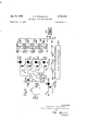
2 Sheets-Sheet l wnt mozamzmo mmi 222 i 8 WEE: zz KEEP 552 Wfiww a 1.1.0 mquilbqu mi as q .:c e 93 me am Jan. 24, 1956 A. A. CHUBB ET AL AUTOMATIC TELEPHONE EXCHANGES Filed Sept. 18, 1951 Jan. 24, 1956 A. A. CHUBB ET AL 2,732,433
AUTOMATIC TELEPHONE EXCHANGES Filed Sept. 18, 1951 2 Sheets-Sheet 2 M/ l/EN TORS FILE kn MDER 4 La CHUS'B A TTORNE Y United States Patent 2,732,433 AUTOMATIC TELEPHONE EXCHANGES Alexander Albert Chnbb, Coventry, and Ronald Mawson, Farnborough, England, and Maurice Moise Levy, Ottawa, Ontario, Canada, assignors to The General Electric Company Limited, London, England Application September 18, 1951, Serial N 247,073
Claims priority, application Great Britain September 22, 1950 5 Claims. (Cl. 179-18) The present invention relates to coding devices suitable for use in an automatic exchange as described in the specification of said co-pending U. S. patent applica tion, Serial No. 247,072.
In the automatic exchange described in the aforesaid co-pending patent application a plurality of communication channels are provided, and in responseto a calling signal from a calling subscriber a free one of these channels is selected. In response to dialling signals the called subscriber is called and the identification of the selected free channel is transmitted to the called subscribers terminal equipment. In order to achieve this a routing device is used and may be as described in the specification of co-pending U. S. patent application Serial No. 247,233, filed September 19, 1951. This routing device requires a set of two or more control signals of predetermined characteristic to be applied to its input terminal in order to establish a connection with one of its output terminals.
An object of the present invention is to provide a cod- A ing device suitable for storing dialling signals from a calling subscriber, converting these signals into a set of control signals suitable for application to the aforesaid routing device, and in addition giving the control signals a characteristic identified with the aforesaid selected free channel.
According to the present invention a coding device comprises two or more selector switching devices, each having a plurality of input terminals, an output terminal, and being adapted, in response to different dialling signals to connect different ones of the input terminals to the output terminal, means for applying control voltages of different, predetermined characteristics to the input terminals respectively of the selector switching devices, means for combining the control voltages appearing at the output terminals of the several selector switching devices to form a set, and means for adding a further characteristic to the set of control voltages. Where the several channels in the automatic exchange described in the first named co-pending application are constituted by interlaced pulse trains, the means for adding the further characteristic to the combined control voltages may comprise a gate device to which the combined control voltages are applied. Pulses in the selected free channel may be applied to the gate device to open the gate recurrently whereby the combined control voltages appear at the output of the gate only during each pulse in the selected channel. The means for adding the further characteristic may comprise means for combining further voltages with the set, the further voltages having characteristics independent of those in the set. For examplethe further voltages may be representative of the aforesaid selected free channel. r I I The control voltages may be, for example, pulses of difierent instants of occurrence, or oscillations of difierent frequencies.
The dialling impulses representing the different digits dialled may be applied to set difierent ones of the selectors switching devices in known manner, and a further switch device may be arranged to prevent the output from at least the last selector switching device to be set, from reaching the output of the coding device.
. The invention will now be described by way of example with reference to the accompanying drawings, in which Figure 1 is a circuit diagram of one embodiment of the invention, and
Figures 2(a), 2(b), 2(a) and 3 are explanatory diagrams.
The detached contact system of references is used in.
Figure 1, this system being as described on page 9 of British Standard 530:1948 Graphical Symbols for Telecommunications published by the British Standards In- In this system, symbols for parts of compoa reference in the form of a fraction in which the numera-' tor is a letter and is the relay reference and the denominator is a number indicating the number of sets of con-- tacts on the relay. For example a relay winding may have the reference X/ 3 indicating that the relay X has three contacts. These would be referenced X1, X2, and X3.
. Referring to Figure 1, a dial DLof an automatic tele- 1 phone set (not shown) is connected in series with a relay coil A and a battery BAT1. Thus operation of the dial DL causes a series of pulses of current to flow through the relay coil A at the standard frequency of 10 P. P. S. It will be assumed that the number dialled has four digits, say 1, 2, 3, 4 respectively.
The pulses of current in the relay coil A cause operation of the contacts A1 at the same rate. These contacts are connected to the wiper of a bank Z1 of a uniselector Z, and the wiper of the bank Z1 is normally on its first contact.
This first contact is connected through the winding of a second uniselector M and a battery BATz to earth. Thus successive operations of the contacts A1 causes the wipers of the uniselector M to be stepped around their bank contacts. The uniselectors and stepping action thereof may be as described in chapter 3 of "Ielephony,
vol. II, by J. Atkinson, published by Sir Isaac Pitman & Sons Ltd.
The bank M1 of the uniselector M has eleven bank contacts, the first of which is a home contact. maining ten bank contacts of M1 are connected to ten terminals MP1 to MP9 and MP0 respectively. Thus in the present example in which the first digit isyl the wiper of the bank M1 is connected to the terminal MP1. A slow acting relay B has one terminal of its operating coil connected to the contacts A1 and the other, through a battery BATs to earth. The relay is arranged to hold between adjacent impulses in each digit dialled and hence becomes operated and released once for each digit dialled.
The contacts B1 of the relay B complete a circuit from earth through the winding of the uniselector Z and a battery BAT4 back to earth. Thus the wipers of the uniselector Z make one forward step after each digit is dialled. Thus when the second digit (2 in this example) is dialled the wiper of the bank X1 is on its second bank' contact. This is connected through the operating winding of a uniselector C and thence through a battery BATs to earth.
to the terminal CPz.
The relay B steps the wiper of the uniselector bank Z1" Patented Jan. 24, 1956 The re- 3 on to its third contact before the third digit is dialled. The third contact of Z1 is connected through the operating winding of a uniselector D and thence through a battery BATe to earth.
The bank D1 of the uniselector D has eleven bank contacts of which the first is an isolated home contact. The remaining ten bank contacts are connected to ten terminals DPI to DPs and DPo respectively. Thus in this example, the wiper of the bank D1 becomes connected to the terminal DPs.
At the end of the third digit the relay B steps the wiper of the uniselector Z on to its fourth contact. The fourth contact is connected to the operating winding of a uniselector U and thence through a battery BAT: to earth.
The bank U1 of the uniselector U has eleven bank contacts of which the first is in isolated home contact. The remaining ten bank contacts are connected to ten terminals UPi to UP!) and UPo respectively. Thus in this example the wiper of the bank U1 becomes connected to the terminal UP4.
The 40 terminals UP; through to MP are connected by suitable connectors (not shown) to the 40 output terminals of like reference respectively of a main pulse geneartor MPG. This pulse generator is arranged in any suitable manner to generate a recurring sequence of 40 pulses which appear at the 40 terminals MP0 to UPs respectively. The pulse generator may be as described in the specification of said copending U. S. Patent Application, Serial No. 247,072. The generated pulses will be referred to by the letters M, C, D and U followed by a subscript corresponding to the subscripts in the references to the terminals at which the pulses appear. Thus in the present example pulses M1, C2, D3 and U4 appear at the wipers of the four uniselector banks M1, C1, D1 and U1 respectively. This set of pulses is regularly recurring as indicated in Figure 2(a).
The pulses of each set are combined through four rectifiers W1 to W4 respectively and applied through a roesistor R and relay contacts Q2 to an output terminal An auxiliary pulse generator APG is connected through a rectifier W5 t0 the end of the resistor R remote from the rectifiers W1 to W4. This pulse generator is arranged to generate relatively broad pulses of a width equal to that of a complete sequence of M, C, D and U pulses, and at a recurrence frequency equal to one fifth of that of the sets of M, C, D and U pulses. Thus the waveform of the pulses provided by the auxiliary pulse generator is as shown at GP in Figure 2(b).
In the absence of pulses from the auxiliary generator APG the rectifier W5 is conducting and hence the sets of pulses from the uniselector banks M1, C1, D1 and U1 are dropped across R. When a pulse appears at the output of the pulse generator APG, however, the rectifier W5 becomes non-conducting and permits pulses to pass from the uniselector banks to the contacts Q2. Thus in the present example only every fifth set of M1, C2, D3 and U4 pulses are passed to the contacts Q2.
Referring again to the uniselector bank Z1, after the last digit has been dialled the relay B steps the Wiper of Z1 on to its fifth contact and hence causes energisation of a relay coil Q from a battery BATa. Thus when, and not until, the wipers of all four uniselector banks M1, C1, D1 and U1 have been set in accordance with the number dialled, the relay contacts Q2 close and the sets of M1, C2, D and U4 pulses gated by the auxiliary generator APG appear at the output terminal OT.
The contacts Q1 hold the relay Q through a switch S1 which is closed before the apparatus is put into use. The switch S1 may, of course, conveniently be contacts of a further relay (not shown).
The uniselector banks M2, C2, D2 and U2 and Z2 are homing banks and may operate as described on pages 259 and 260 of Telephony, volume II, by Atkinson. Thus k. in order to switch oif the apparatus switches S2 to 56 which may also conveniently be contacts of a relay (not shown) are closed to cause all uniselectors to home, and S1 is opened to deenergise the relay Q and hence to open the contacts 02.
In a second embodiment the output of the auxiliary pulse generator APG is of dilfercnt form, the resistor R is removed and the rectifier W5 reversed. The pulse generator APG is arranged to generate pulses which occur after the last U pulse in each set and before the M pulse in the next succeeding set.
For example referring to Figure 3 this shows a set of M1, C2, D and U4 pulses on a larger scale than in Figure 2. After the U4 pulse and before the next succeeding M1 pulses two further pulses ds and u; are added.
We claim:
1. Coding apparatus for automatic exchanges, comprising a main input terminal to receive dialling impulses, a plurality of selector switching devices each having a plurality of input terminals and an output terminal, control apparatus to actuate said selector switching devices in response to dialling impulses, means to apply dialling impulses from said main input terminal to said control apparatus to select different ones of the said input terminals of said selector switching devices for connection to said output terminals thereof respectively, a source of voltages of different characteristics, means to apply said voltages to the input terminals of said selector switching devices, different voltages being applied to different ones of the last said terminals, 2. combining circuit connecting the output terminals of said selector switching devices to provide a combined output from said selector switching devices, a source of signalling voltage, a further combining circuit, a main output terminal, means connecting said further combining circuit between the first said combining circuit and said main output terminal, and means to apply signal voltage from the last said source to said further combining circuit to produce at said main output terminal a signal having characteristics related to said dialling impulses and to a signal from the last said source.
2. Coding apparatus according to claim 1, wherein said further combining circuit comprises a gate device through which said combined output from said selector switching devices is applied to said main output terminal and said signal voltage from the last said source is applied to open and close said gate device whereby the voltage at said main output terminal is in the form of a succession of groups of voltages characteristic of said dialling impulses and whose instants of occurrence are characteristic of said signal voltage.
3. Coding apparatus for automatic exchanges, comprising a main input terminal to receive dialling impulses, a plurality of selector switching devices each having a plurality of input terminals and an output terminal, control apparatus to actuate said selector switching devices in response to dialling impulses, means to apply dialling impulses from said main input terminal to said control apparatus to select different ones of the said input terminals of said selector switching devices for connection to said output terminals thereof respectively, means to generate a plurality of interlaced recurring pulses, means to apply ditferent ones of said recurring pulses to difierent ones of the input terminals of said selector switching devices, a combining circuit connected to the output terminals of said selector switching devices to combine the outputs of said selector switching devices into a recurring group of pulses characteristic of said dialling impluses, a main output terminal, a gate device, means connecting said gate device between said combining circuit and said main output terminal, a source of signalling pulses, and means to connect said source of signalling pulses to said gate device to open and close said gate device, whereby the voltage appearing at said main output terminal is in the form of a group of pulses characteristic of said dialling impulses and recurring at instants determined by the signalling pulses applied to said gate device from said source of signalling pulses.
4. Coding apparatus for automatic exchanges, comprising a main input terminal to receive dialling impulses, a plurality of selector switching devices each having a plurality of input terminals and an output terminal, control apparatus to actuate said selector switching devices in response to dialling impulses, means to apply dialling impulses from said main input terminal to said control apparatus to select diiferent ones of the said input terminals of said selector switching devices for connection to said output terminals thereof respectively, means to generate a plurality of interlaced recurring pulses, means to apply different ones of said recurring pulses to different ones of the input terminals of said selector switching devices, a combining circuit connected to the output terminals of said selector switching devices to combine the outputs of said selector switching devices into a recurring group of pulses characteristic of said dialling impulses, a main output terminal, a further combining circuit, means connecting said further combining circuit between the first said combining circuit and said main output terminal, a source of signalling pulses, and means to apply signalling pulses from the last said source to said further combining circuit for combination with said recurring group.
5. Coding apparatus for automatic exchanges, comprising a main input terminal to receive dialling impulses, a plurality of selector switching devices each having a plurality of input terminals and an output terminal, control apparatus to actuate said selector switching devices in response to dialling impulses, means to apply dialling impulses from said main in;;ut terminal to said control apparatus to select different ones of the said input terminals of said selector switching devices for connection to said output terminals thereof respectively, a source of voltages of different characteristics, means to apply said voltages to the input terminals of said selector switching devices, different voltages being applied to difierent ones of the last said terminals, a combining circuit connecting the output terminals of said selector switching devices to provide a combined output from said selector switching devices, a source of signalling voltage, means for combining a signal voltage from the last named source with said combined output, a main output terminal and means applying the signal voltage combined with the combined output to said main output terminal whereby to produce at said main output terminal a signal having character istics related to said dialling impulses and to a signal from the last named source.
References Cited in the file of this patent UNITED STATES PATENTS 2,379,715 Hubbard July 3, 1945 2,457,149 Herbst Dec. 28, 1948 2,563,589 Den Hertog Aug. 7, 1951 2,570,274 Ransom Oct. 9, 1951 2,688,662 Den Hertog et a1 Sept. 7, 1954
Applications Claiming Priority (1)
| Application Number | Priority Date | Filing Date | Title |
|---|---|---|---|
| GB1042298X | 1950-09-22 |
Publications (1)
| Publication Number | Publication Date |
|---|---|
| US2732433A true US2732433A (en) | 1956-01-24 |
Family
ID=10869927
Family Applications (2)
| Application Number | Title | Priority Date | Filing Date |
|---|---|---|---|
| US2732433D Expired - Lifetime US2732433A (en) | 1950-09-22 | Automatic telephone exchanges | |
| US24680D Expired USRE24680E (en) | 1950-09-22 | Automatic telephone exchanges |
Family Applications After (1)
| Application Number | Title | Priority Date | Filing Date |
|---|---|---|---|
| US24680D Expired USRE24680E (en) | 1950-09-22 | Automatic telephone exchanges |
Country Status (2)
| Country | Link |
|---|---|
| US (2) | USRE24680E (en) |
| FR (1) | FR1042298A (en) |
Citations (5)
| Publication number | Priority date | Publication date | Assignee | Title |
|---|---|---|---|---|
| US2379715A (en) * | 1942-10-09 | 1945-07-03 | Bell Telephone Labor Inc | Communication system |
| US2457149A (en) * | 1947-03-20 | 1948-12-28 | Int Standard Electric Corp | Selective signaling circuit |
| US2563589A (en) * | 1949-06-02 | 1951-08-07 | Den hertog | |
| US2570274A (en) * | 1946-03-14 | 1951-10-09 | Int Standard Electric Corp | Electron beam switching tube and system |
| US2688662A (en) * | 1950-01-16 | 1954-09-07 | Int Standard Electric Corp | Means for automatically detecting a change of condition in any one of a number of electrical circuits from a common circuit |
-
0
- US US2732433D patent/US2732433A/en not_active Expired - Lifetime
- US US24680D patent/USRE24680E/en not_active Expired
-
1951
- 1951-09-19 FR FR1042298D patent/FR1042298A/en not_active Expired
Patent Citations (5)
| Publication number | Priority date | Publication date | Assignee | Title |
|---|---|---|---|---|
| US2379715A (en) * | 1942-10-09 | 1945-07-03 | Bell Telephone Labor Inc | Communication system |
| US2570274A (en) * | 1946-03-14 | 1951-10-09 | Int Standard Electric Corp | Electron beam switching tube and system |
| US2457149A (en) * | 1947-03-20 | 1948-12-28 | Int Standard Electric Corp | Selective signaling circuit |
| US2563589A (en) * | 1949-06-02 | 1951-08-07 | Den hertog | |
| US2688662A (en) * | 1950-01-16 | 1954-09-07 | Int Standard Electric Corp | Means for automatically detecting a change of condition in any one of a number of electrical circuits from a common circuit |
Also Published As
| Publication number | Publication date |
|---|---|
| FR1042298A (en) | 1953-10-30 |
| USRE24680E (en) | 1959-08-11 |
Similar Documents
| Publication | Publication Date | Title |
|---|---|---|
| US2317471A (en) | Selection system | |
| US2754367A (en) | Automatic exchange | |
| US2912511A (en) | Translator using diodes and transformers | |
| US2326478A (en) | Selection system | |
| US2629019A (en) | Selector marking system | |
| US2613278A (en) | Telephone system | |
| US1691410A (en) | Automatic telephone system | |
| US2850576A (en) | Line concentrator system | |
| US2732433A (en) | Automatic telephone exchanges | |
| US2651677A (en) | Electrical intercommunication system | |
| US3311705A (en) | Line concentrator and its associated circuits in a time multiplex transmission system | |
| US2490054A (en) | Party line telephone system | |
| US2552792A (en) | Telephone system | |
| US2025880A (en) | Telephone system | |
| US2736773A (en) | Automatic exchanges | |
| US1805778A (en) | Telephone system | |
| US2876286A (en) | Arrangement for the identification of special service apparatus required for connections in a telecommunication system | |
| USRE24679E (en) | Automatic telephone systems | |
| US3127479A (en) | Telephone switching system | |
| US1874684A (en) | Telephone system | |
| US2938960A (en) | Alternate routing in a step-by-step telephone system | |
| US2530104A (en) | Relay automatic telephone system | |
| US2986604A (en) | Dial telephone office arranged for register-sender control of two-motion step-by-step switches having multilevel trunk groups | |
| US3267217A (en) | Circuit arrangement for the connection of time multiplex telephone systems | |
| US2654001A (en) | Sequence switch circuit |