US2729447A - Two speed press feeder - Google Patents
Two speed press feeder Download PDFInfo
- Publication number
- US2729447A US2729447A US324092A US32409252A US2729447A US 2729447 A US2729447 A US 2729447A US 324092 A US324092 A US 324092A US 32409252 A US32409252 A US 32409252A US 2729447 A US2729447 A US 2729447A
- Authority
- US
- United States
- Prior art keywords
- stock
- clutch
- speed
- drive
- contacts
- Prior art date
- Legal status (The legal status is an assumption and is not a legal conclusion. Google has not performed a legal analysis and makes no representation as to the accuracy of the status listed.)
- Expired - Lifetime
Links
Images


Classifications
-
- B—PERFORMING OPERATIONS; TRANSPORTING
- B21—MECHANICAL METAL-WORKING WITHOUT ESSENTIALLY REMOVING MATERIAL; PUNCHING METAL
- B21D—WORKING OR PROCESSING OF SHEET METAL OR METAL TUBES, RODS OR PROFILES WITHOUT ESSENTIALLY REMOVING MATERIAL; PUNCHING METAL
- B21D43/00—Feeding, positioning or storing devices combined with, or arranged in, or specially adapted for use in connection with, apparatus for working or processing sheet metal, metal tubes or metal profiles; Associations therewith of cutting devices
- B21D43/02—Advancing work in relation to the stroke of the die or tool
- B21D43/04—Advancing work in relation to the stroke of the die or tool by means in mechanical engagement with the work
- B21D43/08—Advancing work in relation to the stroke of the die or tool by means in mechanical engagement with the work by rollers
- B21D43/09—Advancing work in relation to the stroke of the die or tool by means in mechanical engagement with the work by rollers by one or more pairs of rollers for feeding sheet or strip material
Definitions
- This invention relates to strip stock feeders and in particular to drive arrangements for selectively operating a strip stock feeder at any of two or more substantially different speeds.
- Strip stock feeders and straightening devices are commonly employed with punch presses, power operated shears, and similar apparatus where it is desired to advance a strip stock through a certain distance for each operation of the machine.
- the ordinary feeding devices usually driven by the mechanism of the punch press or shears, are satisfactory for small increments of feed but are not satisfactory if the stock must be fed a substantial distance during each operation of the machine.
- the principal object of this invention is to provide a strip stock feeding mechanism that is suitable for feeding any desired length of stock for each cycle and whichmay be very easily adjusted for various lengths of feed.
- Another object of the invention is to provide a motordriven feed roll that may be selectively operated at either of two speeds to provide a fast feed for the greater part of the feeding cycle and a slow speed for the remaining increment of the cycle to provide an accurate length of feed for each cycle.
- Another object of the invention is to control a multispeed feeding apparatus by means of limit switches arranged in the path of travel of the strip stock and operatively connected first to reduce the speed of the feed as the end of a feeding cycle is approached and then to. stop the feed at the end of the cycle.
- a still further object is to provide friction clutches in each of two or more power transmission systems to se lectively operate the feed rolls at any of a number of pre-selected speeds.
- a still further object of the invention is to provide a clutchbetween the output shaft of a high-ratio gear-reduction unit and the feed roll-so that the clutch may serve as a brake to quickly reduce the speed of the feed rolls from a fast to a slow speed and positively continue the feed at a slow speed determined by the gear reduction drive.
- a still further object of the invention is to employ a plurality of electro-pneumatically controlled clutches to selectively connect the feed rolls to any of a plurality of driving mechanisms operated at different speeds.
- a still further object of the invention is to provide for a plurality of feeding speeds by providing a plurality of feed rolls operated at different speeds and selectively engaged with the stock.
- one or more drive motors operating through separate power transmission paths are arranged to selectively drive strip stock at any of several speeds depending upon which of the several transmission paths are engaged.
- the transmission paths may include speed reducers and clutches arranged to.stop or drivea 2,729,447 Fate nted Jan. 3, 1956 2 single set of feed rolls at any of several speeds or may include separate speed reducing units connected to separate speed rolls that selectively engage the stock to be fed.
- a single drive motor may be arranged to drive each of the separate speed reducing units or separate motors may be provided.
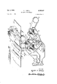
- Figure I is a side elevation in somewhat schematic form showing the general arrangement of a strip stock feeder and power shears to which the stock is being fed.
- Figure II is a perspective diagram showing the essential elements of the drive mechanism and their coopera tion.
- Figure III is an isometric view, with parts cut away, to show the clutches employed in the power transmission systems.
- Figure IV is a simplified schematic diagram illustrating the use of one motor to drive a single feed roller at either of two speeds.
- Figure V is a schematic diagram illustrating the use of separate motors and separate feed rollers arranged to operate according to the invention.
- Figure VI is a schematic wiring diagram of a control system suitable for use with the apparatus.
- Figure VIa is a key diagram for Figure VI.
- apparatus for feeding strip stock 1 from a stock reel 2 may comprise a pair of power driven reel supporting rollers 3 and 4 and a feeding and straightening device 5 that draws the strip stock 1 from the reel 2 and delivers it to a power driven shears 6.
- a punch press or similar machine may be substituted for the shears 6.
- the reel support rolls 3 and 4, the straightening device 5, and mechanism for driving these elements are mounted in a frame 7.
- Power for driving the reel supporting rolls 3 and 4 is obtained from a motor 8 operatively connected by means, not shown, to a speed reducer 9 having a pair of sprockets 10 and 11 on its output shaft.
- a motor 8 operatively connected by means, not shown, to a speed reducer 9 having a pair of sprockets 10 and 11 on its output shaft.
- the sprocket 11 drives through a chain 12 to a clutch l3 rotatably mounted in the central part of the frame 7.
- Power A delivered from the motor 8 to the reel support roll 3 as long as the clutch 13 is engaged.
- the second reel support roll 4 may be connected by a chain drive 17 to the reel support roll 3 so that both rolls are power driven and turn at the same speed.
- the speed reducer 9, driven by the motor 8, also supplies power for the feeder and straightener device 5 by way of the sprocket 10, a chain drive 18, a second clutch 19 mounted on a common shaft 20, a chain sprocket 21, and a chain 22 driving sprockets 23 and 24 mounted on 4 rolls 25 and 26 of the feeding device 5.
- the additional feed rolls may be gear driven from the feed rolls 25 and 26 which are driven by the motor 8 as long as the second clutch 19 on the shaft 20 is engaged.
- a pressure roller 27 forces the stock against the roller 25 so that the stock is positively fed as long as the rolls turn.
- a third clutch 28 also mounted on the shaft 20 is driven by a chain 29 engaging a drive sprocket 30 mounted on a slow speed output shaft of a second motor 31, shown in Figure II but not in Figure I.
- the drive through the sprocket 30 and third clutch 28 is arranged to drive the 3 feed roll 25 at a reduced speed as compared to the drive through the second clutch 19.
- a brake 32 (in Figure II) is mounted on the shaft of the feed roll 25 and arranged to hold the feed rolls stationary when the clutches 19 and 28 are disengaged.
- the clutches 13, 19, and 28 are electro-pneumatically controlled by a control system that includes a first switch 33 that is periodically actuated by a cam on a drive wheel 34 of the operating mechanism of the power shears 6.
- the switch 33 is arranged to be operated just as the drive mechanism raises a knife 35 clear of the stock 1.
- the clutch 32 is operated simultaneously with the clutch 19 so that as the clutch 19 is disengaged the brake 32 engages to aid the, slow speed drive, including the clutch 28, in slowing up the strip stock and stabilizing the movement of the stock as it is driven at slow speed.
- the clutch 28 is disengaged to stop the feeder 5.
- the feeder is held stationary with both clutches deenergized until the length of stock is cut off and the cut piece delivered to a stacker or other stock receiving mechanism.
- the clutch 13 controlling the flow of power to the reel support rolls 3 and.
- a fourth switch 38 having a feeler 39 riding on the strip stock 1 when the stock overruns and forms a loop.
- This switch is arranged to disengage the clutch 13 and hold it disengaged until the feeder 5 has taken up the slack in the open loop.
- the drive mechanism in particular the cooperation of the high and low speed drives, is shown in greater detail in Figure II.
- the clutches 13, 19, and 28 are pneumatically controlled. Air at constant pressure, which may conveniently be at 50 to 100 pounds per square inch, is supplied through a pipe 40 having a plurality of branches 41, 42 and 43 controlled by electrically actuated valves 44, 45, and 46 respectively.
- Each of the valves 44 to 46 inclusive is of a three-way type arranged to permit flow of air from the supply pipe 40 into the controlled branch when the valve is energized and to open the controlled branch to the atmosphere whenever the valve control is de-energized.
- the valve 44 and pipe 41 supply air to the pneumatically actuated clutch 28 in the slow speed drive.
- the valve 46 and the controlled pipe 43 are arranged to control the clutch 13 in the drive to the cradle.
- the third valve, the valve 45 controls air flow to the branch pipe 42 which divides with a first branch 47 leading to a pneumatic cylinder 48 which is part of the control for the brake 32.
- the pneumatic cylinder 48 includes a piston 49 and a piston rod 50 connected, through a crank arm 51 and rotatable shaft 52 to turn an eccentric cam 53 inserted between a pair of brake shoes 54 and 55 of the brake 32.
- the cam 53 is arranged to separate the brake shoes 54 and release the brake whenever air pressure is applied through the pipe 47.
- each clutch comprises an end plate 59 and a generally cup-shaped member 60.
- the end plate 59 and the cup 60 together constitute a housing that is rotatably mounted by ball bearings 61 and 62 on the shaft 20.
- the drive sprocket for the corresponding chain drive 18 or 29 is rigidly mounted on the cup-shaped member 60.
- a driven member 63 of the clutch comprises a disk mounted on and keyed to the shaft 20.
- the driven member 63 carries a plurality of friction plugs 64 that are in the form of short, solid cylinders axially slidable in bores in the driven member 63 and engaged between a radially extending clutch face 65 in the cupshaped member 60 and an annular pressure plate 66 that is axially slidable on inwardly directed lugs at the rim of the cup-shaped housing 60.
- the clutch is engaged by air pressure supplied through a rotatable coupling into an end chamber 67 of the clutch. From the chamber 67 the air flows through drilled holes 68 into a chamber formed between an inside surface 69 of the end plate 59 and a resilient annular diaphragm 70 the inner and outer peripheries of which are attached to the face of the end plate 59.
- This particular clutch construction is comparatively easy to make and assemble as well as to keep in condition and repair.
- the end plate 59 may be easily removed taking with it the annular diaphragm 70 thus exposing the pressure plate 66.
- the ball bearing 62 fitted in the end plate 59 stays with the end plate.
- the pressure plate 66 may then be slipped out of the cup-shaped housing thus exposing the friction plugs 64. It should be noted that it is unnecessary to disturb the diaphragm 70 in this operation.
- Figure IV is a simple schematic illustration showing a single motor 71 arranged to drive simultaneously a pair of speed reducing units 72 and 73.
- the first speed reducer 72 op ating at a fairly low r du tion r io r es hro gh a sprocket 74, chain drive 75, sprocket 76, and clutch 77 to a common shaft 78.
- the shaft 78 corresponding to the shaft 20, is connected through a chain drive 79 to a feed roll 80 adapted to feed strip stock material 81.
- a slow speed drive for the strip stock material 81 is obtained through a second speed reducer 73 operating ata high ratio and through a chain drive 83 and clutch 84 also connected to the common shaft 78.
- the slow speed clutch 84 may be engaged by applying air pressure through a pipe 85.
- This system differs from that first described by employing a single motor to drive both of the speed reducers that are selectively engaged to feed the strip stock material.
- the multi-speed drive may also be obtained by the arrangement shown in Figure V wherein a first motor 86 is connected through a speed reducer 87 and chain drive 88 to drive a first roll 89. Air pressure applied to a pneumatic cylinder 90 forces a resiliently supported pressure roller 91 against the stock being fed to pinch it between the rolls 89 and 91 and thus provide sufficient friction to move the material at high speed. Slow speed drive for the material is provided by a second motor 92 which, through a high ratio speed reducer 93 and chain drive 94 drives a second feed roll 95.
- both of the motors 86 and 92 and both of the feed rollers 89 and 95 run continuously at their respective speeds while the rate of feed of material is controlled by operating one or another of the pneumatic cylinders and pressure rollers.
- the rate of feed may be changed abruptly since it is not necessary to change the speed of the driving motors when changing from one speed to another.
- FIG. VI An electrical control system suitable for controlling the valves 44, 45, and 46 and the motors 8 and 31 is illustrated schematically in Figure VI and its key, Figure VIa.
- this control system three phase electrical power is supplied to leads L1, L2, and L3 at a voltage suitable for operating the motors 8 and 31.
- the voltage between the leads L1 and L2 is applied to a primary 100 of a stepdown transformer 101 having a secondary coil 102 connected to low voltage supply lead L and L6.
- the leads L1, L2 and L3 are supplied with 440 volt power and the transformer 101 is arranged to deliver approximately 110 volts to the leads L5 and L6.
- the control equipment comprises a motor starter MSl indicated by the first line at the left in Figure VIa and connected to control the slow speed drive motor 31; a pair of motor starters MS2F and MSZR, indicated by the third and fourth lines of Figure VIa and adapted to control the motor 8 in forward and reverse operation respectively; a timing relay T, indicated by the second line in Figure VIa, adapted to delay the operation of the high speed clutch 19 until after the motor 8 has had time to reach full speed; a control relay CR1, indicated by the fifth line in diagram VIa, and arranged to control the valve 46 which in turn controls the operation of the cradle drive clutch 13; a second control relay CR2 adapted to control the high speed clutch 19; and a third control relay CR3 adapted to control the low speed clutch 28.
- a motor starter MSl indicated by the first line at the left in Figure VIa and connected to control the slow speed drive motor 31
- a pair of motor starters MS2F and MSZR indicated by the third and fourth lines of Figure VIa and adapted to
- a master stop button 103 is provided to control all of the control circuit
- a motor start button 104 is arranged to start the slow speed motor 31 and high speed motor 8 in the forward direction
- a manually operated reverse switch 105 is arranged to stop the slow speed motor 31 and start the high speed motor 8 in its reverse direction.
- a forward inch control switch 106 is arranged to permit the drive to operate at slow speed during the portion of a feeding cycle when it would normally operate at high speed.
- the start button 104 allows current to reverse or at slow speed through any part of the flow from the lead L5 through the stop switch 103, a lead 107,.normally closed contacts CR1-1 and CR2-1, a lead 108, contacts 109 of the start button 104, a lead 110, contacts 111 of the reversing switch 105, through an operating coil MS1-C of the motor starter M81 and through its overload device to the lead L6.
- This flow of current energizes the motor starter MS1 so that it closes its contacts MSl-I to complete a circuit between the leads 107 and 110, and closes its contacts MS1-2, MS1-3 and MS14 to start the slow speed motor 31.
- the contacts MSl-1 provide a holding circuit so that the start button 104 may be released. Energization of the lead allows current to flow through contacts 112 of the reversing switch 105, normally closed contacts 2R-1 and operating coil MS2F-C to energize the forward motor starter MS2F for the motor 8. When this starter operates it closes its contacts F-1, F-2 and F3 to start the motor 8 in the forward direction. It likewise closes its contacts F4 to energize an operating coil T-C of the timer T.
- the fourth switch 38 which is actuated by opening of the loop of strip stock when the cradle overruns the feeder.
- the switch 38 is not operated it allows current to flow through an operating coil CRl-C of the first control relay CR1. Operation of this relay closes its contacts CR1-1, CR1-2 to energize the valve 46 controlling the air pressure to the cradle clutch 13 so that the cradle is driven to supply strip stock to the feeder. If the stock overruns, the switch 38 opens the circuit to disengage the cradle clutch 13.
- the feeder itself may be started either by closure of the first switch 33 on the shears or by operation by a feed start button 115. Closure of either allows current to flow through a circuit comprising a lead 116, contacts 117 of the slow down limit switch 36, normally closed contacts 118 of the forward inching button 106, normally closed contacts CR31 of the third control relay, contacts T-1 of the timer and operating coil CR2-C of the second control relay.
- this control relay CR2 operates it closes its holding contacts CR2-2 to bypass the start button or switch 33 and likewise closes its contacts CR23, CR2-4 to energize the control valve 45 and thus engage the high speed drive to the feeder.
- the system then feeds material at high speed until the leading edge of the material reaches and operates the slow down switch 36.
- This switch by opening its contacts 117, de-energizes the second control relay CR-2 and thus disengages the high speed clutch.
- the slow down switch 36 closes its contacts 119 so that current may flow from the lead 113 through the stopping limit switch 37, the contacts 119 of the slow down switch 36, contacts 120 of the inching switch 106, normally closed contacts CR2-5 and operating coil CR3C of the third control relay CR3.
- This control relay which is energized as soon as the slow down limit switch 36 has been actuated and the second control relay CR2 has opened, closes its contacts CR3-2 and CR3-3 to energize the control valve 44 and thus engage the slow speed clutch 28.
- This control relay is held energized until the stopping limit switch 37 is actuated at which time the circuit through the switch 37 is broken and the feed is stopped. It should be noted that during the slow down and stopping of the feed that the cradle drive is energized intermittently by operation of the stock operated switch 38 so that it maintains an open loop of stock available for the feeder.
- the operator of the machine may .at times wish to rewind stock onto the supply reel.
- the equipment is constructed so that it may be operated in reverse. Normally a reversal is made by'first stopping the motors by operating the stop button 1&3v and then pressing the reverse button. 105 to close its contacts 122 so that, as long as CR1 and. CR2 are de-energized, current may flow from the lead 168 through the now closed contacts 122, lead 123, normally closed contacts 2F-5, and operating coil MSZR-C.
- the reverse button 106 opens its contacts 111 and 112 to prevent operation of the slow speed motor starter M51 or the forward starter MSZF.
- MSZR now energized opens its contacts 2Ri, closes its contacts 2R--3 to energize the timer and closes its contacts 2R-4, -5, -6 to energize the motor 3 for reverse rotation.
- the opening of contact 2R2 interrupts the current to the cradle drive control.
- the reverse starter also closes its contacts 2R-7 to complete a circuit from the lead 107, through normally closed contacts 124 of the start button 104, to the lead 123 and thus energize the reverse starter MS2R independently of the reverse button 105.
- the motor may be stopped by pushing the stop button 103.
- the equipment just described may be reversed without using the stop button 103.
- the opening of contacts 111 stops the slow speedv motor, and the opening of contacts 112 opens the high speed motor which, in turn de-energizes the timer which opens the lead to the high speed control relay CR2.
- the reverse direction starter MSZR is energized and the motor reversed.
- a feeder for strip .stock in combination, .a power source, a stock drive roll, a first power transmission system leading from the source of power to the stock drive roll and adapted to drive the stock drive roll at a first speed, a second power transmission system leading from the sourceof power to the stock drive roll and adapted to drive the roll at a second speed slower than the first, means operatively connected to the systems for selectively engaging and disengaging each of said transmission systems, and means including portions located at predetermined positions to be engaged by the strip stock and operatively connected to said engaging and disengaging means for successively engaging and disengaging said transmission systems as the leading end of the stock is moved to the predetermined positions whereby the stock is started, rapidly moved to a first position, and slowly moved to a final position and stopped under control of the stock drive roll.
- a brake connected to the drive roll, and means for engaging the brake simultaneousiy with engagement of the slow speed system.
- a power source including a motor, a pair of speed reducing transmissions driven by said motor, a first providing fast feed and the other slow feed, at least one feed roll continuously in contact with the stock, a pair of clutches adapted to selectively connect each of said transmissions to the feed roll, means operative to engage the clutch of the first transmission, means operative by feeding of the stock to a selected position for disengaging the clutch of the first transmission and engaging the other, and means operative by movement of the stock to a second position for disengaging the second clutch to stop said feed roll.
- a brake connected to the drive roll, and means for engaging the brake simultaneously with engagement of the second clutch.
- a feeder for strip stock according to claim 3 including a separate motor for each of the speed reducing transmissions.
- a feeder for strip stock in combination, a pair of power transmissions, means for driving the transmissions, a pneumaticaliy operative clutch connected to and driven by the output of each transmission, common drive means operatively connected to each of said clutches to be driven thereby, drive rolls for the strip stock, said rolls being drivingly connected to the common drive means, means for engaging a first of said clutches for high speed operation, means responsive to movement of the strip stock to a first position for disengaging the first clutch and engaging the other, and means responsive to movement of the stock to a second position for disengaging the second clutch to stop the rolls.
- a feeder for strip stock in combination, a pair of power transmission means of ditferent transmission speed ratios, electric motor means operatively connected to the transmission means, feed rolls for the strip stock, a pair of clutches one for each power transmission means for connecting the transmission means to the feed rolls, electrical control means for the clutches, means actuating the electrical control to engage the first clutch, a first limit switch in the path of the strip stock operatively connected to the electrical control means for disengaging the first of the clutches and engaging the second according to the travel of the strip stock to a first position, and a second limit switch in the path of the stock operatively connected to the electrical control means to disengage the second clutch and stop the rolls.
- a pair of geared speed reducers electric motor means for driving the speed reducers, said reducers having substantially different output speeds
- a clutch operatively connected to each speed reducer output
- common drive means driven by said clutches
- feed rollers in continuous contact with the strip stock and driven by the common drive means
- electro-pneumatic means arranged to control the clutches, means operative through the electro-pneumatic means to engage the clutch providing the higher speed
- a first limit switch arranged in the path of stock being fed from the feed rollers and connected to the electro-pneumatic clutch control to disengage the higher speed clutch and engage the other
- a second limit switch in the path of the stock operatively connected to disengage the lower speed clutches and stop the feed rollers.
- a pair of geared speed reducers having difierent speed ratios, electric motor means for driving the speed reducers, common drive means, a pair of clutches each having a driven element connected to said common drive means, said clutches having driving elements connected to the outputs of said speed reducers, electro-pneumatic means for controlling the clutches, feed rolls continuously contacting the strip stock and operatively driven by the common drive means, means for causing said electro-pneumatic means 'to engage the clutch providing the higher speed, and first and second limit switches actuated by the stock being fed and connected to the electro-pneumatic clutch controls, the first limit switch being eflective to cause disengagement of the engaged clutch and engagement of the second clutch to transfer the drive to the rolls when the stock reaches a first position and the second limit switch being effective to disengage the second clutch at a second position of the stock.
Landscapes
- Engineering & Computer Science (AREA)
- Mechanical Engineering (AREA)
- Controlling Rewinding, Feeding, Winding, Or Abnormalities Of Webs (AREA)
Description
Jan. 3, 1956 A. F. GROLL TWO SPEED PRESS FEEDER 5 Sheets-Sheet 1 Filed Dec. 4. 1952 .4 L WW m6 F. W
N W5 A Jan. 3, 1956 A. F. GROLL' TWO SPEED PRESS FEEDER 5 Sheets-Sheet 2 Filed Dec. 4. 1952 INVENTOR. AV/N F GROLL .47 ENE Jan. 3, 1956 A. F. GROLL 2,729,447
TWO SPEED PRESS FEEDER Filed Dec. 4, 1952 5 Sheets-Sheet 5 IN V EN TOR.
Jan. 3, 1956 A. F. GROLL 2,729,447
TWO SPEED PRESS FEEDER Filed Dec. 4. 1952 5 Sheets-Sheet 4 AIR 96 i z I 90 Z 2 f-Q a a I INVENTOR. AL |///V F GPO/.L
United States Patent TWO SPEED PRESS FEEDER Alvin F. Groll, Napoleon, Ohio Application December 4, 1952, Serial No. 324,092
9 Claims. (Cl. 271--2.4)
This invention relates to strip stock feeders and in particular to drive arrangements for selectively operating a strip stock feeder at any of two or more substantially different speeds.
Strip stock feeders and straightening devices are commonly employed with punch presses, power operated shears, and similar apparatus where it is desired to advance a strip stock through a certain distance for each operation of the machine. The ordinary feeding devices, usually driven by the mechanism of the punch press or shears, are satisfactory for small increments of feed but are not satisfactory if the stock must be fed a substantial distance during each operation of the machine.
The principal object of this invention is to provide a strip stock feeding mechanism that is suitable for feeding any desired length of stock for each cycle and whichmay be very easily adjusted for various lengths of feed.
Another object of the invention is to provide a motordriven feed roll that may be selectively operated at either of two speeds to provide a fast feed for the greater part of the feeding cycle and a slow speed for the remaining increment of the cycle to provide an accurate length of feed for each cycle.
Another object of the invention is to control a multispeed feeding apparatus by means of limit switches arranged in the path of travel of the strip stock and operatively connected first to reduce the speed of the feed as the end of a feeding cycle is approached and then to. stop the feed at the end of the cycle.
A still further object is to provide friction clutches in each of two or more power transmission systems to se lectively operate the feed rolls at any of a number of pre-selected speeds.
A still further object of the invention is to provide a clutchbetween the output shaft of a high-ratio gear-reduction unit and the feed roll-so that the clutch may serve as a brake to quickly reduce the speed of the feed rolls from a fast to a slow speed and positively continue the feed at a slow speed determined by the gear reduction drive.
A still further object of the invention is to employ a plurality of electro-pneumatically controlled clutches to selectively connect the feed rolls to any of a plurality of driving mechanisms operated at different speeds.
. A still further object of the invention is to provide for a plurality of feeding speeds by providing a plurality of feed rolls operated at different speeds and selectively engaged with the stock.
More specific advantages are apparent from the following description of an apparatus constructed according to the invention.
According to the invention, one or more drive motors operating through separate power transmission paths are arranged to selectively drive strip stock at any of several speeds depending upon which of the several transmission paths are engaged. The transmission paths may include speed reducers and clutches arranged to.stop or drivea 2,729,447 Fate nted Jan. 3, 1956 2 single set of feed rolls at any of several speeds or may include separate speed reducing units connected to separate speed rolls that selectively engage the stock to be fed. A single drive motor may be arranged to drive each of the separate speed reducing units or separate motors may be provided.
A preferred embodiment and modifications of the invention are illustrated in the accompanying drawings.
In the drawings:
Figure I is a side elevation in somewhat schematic form showing the general arrangement of a strip stock feeder and power shears to which the stock is being fed.
Figure II is a perspective diagram showing the essential elements of the drive mechanism and their coopera tion.
Figure III is an isometric view, with parts cut away, to show the clutches employed in the power transmission systems.
Figure IV is a simplified schematic diagram illustrating the use of one motor to drive a single feed roller at either of two speeds.
Figure V is a schematic diagram illustrating the use of separate motors and separate feed rollers arranged to operate according to the invention.
Figure VI is a schematic wiring diagram of a control system suitable for use with the apparatus.
Figure VIa is a key diagram for Figure VI.
These specific figures and the accompanying description are intended to merely illustrate the invention but not to impose limitations on its scope.
Referring now to Figure I, apparatus for feeding strip stock 1 from a stock reel 2 may comprise a pair of power driven reel supporting rollers 3 and 4 and a feeding and straightening device 5 that draws the strip stock 1 from the reel 2 and delivers it to a power driven shears 6. A punch press or similar machine may be substituted for the shears 6.
The reel support rolls 3 and 4, the straightening device 5, and mechanism for driving these elements are mounted in a frame 7.
Power for driving the reel supporting rolls 3 and 4 is obtained from a motor 8 operatively connected by means, not shown, to a speed reducer 9 having a pair of sprockets 10 and 11 on its output shaft. (In Figure I the sprocket 11 is located immediately behind the sprocket 10.) The sprocket 11 drives through a chain 12 to a clutch l3 rotatably mounted in the central part of the frame 7. Power A delivered from the motor 8 to the reel support roll 3 as long as the clutch 13 is engaged. If desired, the second reel support roll 4 may be connected by a chain drive 17 to the reel support roll 3 so that both rolls are power driven and turn at the same speed.
The speed reducer 9, driven by the motor 8, also supplies power for the feeder and straightener device 5 by way of the sprocket 10, a chain drive 18, a second clutch 19 mounted on a common shaft 20, a chain sprocket 21, and a chain 22 driving sprockets 23 and 24 mounted on 4 rolls 25 and 26 of the feeding device 5. The additional feed rolls may be gear driven from the feed rolls 25 and 26 which are driven by the motor 8 as long as the second clutch 19 on the shaft 20 is engaged. A pressure roller 27 forces the stock against the roller 25 so that the stock is positively fed as long as the rolls turn.
A third clutch 28 also mounted on the shaft 20 is driven by a chain 29 engaging a drive sprocket 30 mounted on a slow speed output shaft of a second motor 31, shown in Figure II but not in Figure I. The drive through the sprocket 30 and third clutch 28 is arranged to drive the 3 feed roll 25 at a reduced speed as compared to the drive through the second clutch 19. A brake 32 (in Figure II) is mounted on the shaft of the feed roll 25 and arranged to hold the feed rolls stationary when the clutches 19 and 28 are disengaged.
The clutches 13, 19, and 28 are electro-pneumatically controlled by a control system that includes a first switch 33 that is periodically actuated by a cam on a drive wheel 34 of the operating mechanism of the power shears 6. The switch 33 is arranged to be operated just as the drive mechanism raises a knife 35 clear of the stock 1. When the switch 33 is actuated the clutches 13 and 19 are engaged so that stock is fed rapidly through the shears until the leading edge strikes a first limit switch 36. Actuation of the limit switch 36, by means described in detail later, disengages the clutches 13 and. 1.59 and engages the slow speed clutch 28. The brake. 32 is operated simultaneously with the clutch 19 so that as the clutch 19 is disengaged the brake 32 engages to aid the, slow speed drive, including the clutch 28, in slowing up the strip stock and stabilizing the movement of the stock as it is driven at slow speed. As the leading edge passes the limit switch 36 and reaches a second limit switch 37 the clutch 28 is disengaged to stop the feeder 5. The feeder is held stationary with both clutches deenergized until the length of stock is cut off and the cut piece delivered to a stacker or other stock receiving mechanism. To control the overrun of the cradle the clutch 13 controlling the flow of power to the reel support rolls 3 and. 4 is engaged and disengaged at the same time as the clutch 19 is engaged and disengaged but is, in addition, also controlled by a fourth switch 38 having a feeler 39 riding on the strip stock 1 when the stock overruns and forms a loop. As the feed rolls 3 and 4 tend to advance the stock slightly faster than the feeding device 5 draws it an open loop of stock forms and actuates the switch 38. This switch is arranged to disengage the clutch 13 and hold it disengaged until the feeder 5 has taken up the slack in the open loop.
The drive mechanism, in particular the cooperation of the high and low speed drives, is shown in greater detail in Figure II. As was mentioned previously, the clutches 13, 19, and 28 are pneumatically controlled. Air at constant pressure, which may conveniently be at 50 to 100 pounds per square inch, is supplied through a pipe 40 having a plurality of branches 41, 42 and 43 controlled by electrically actuated valves 44, 45, and 46 respectively. Each of the valves 44 to 46 inclusive is of a three-way type arranged to permit flow of air from the supply pipe 40 into the controlled branch when the valve is energized and to open the controlled branch to the atmosphere whenever the valve control is de-energized.
The valve 44 and pipe 41 supply air to the pneumatically actuated clutch 28 in the slow speed drive. The valve 46 and the controlled pipe 43 are arranged to control the clutch 13 in the drive to the cradle. The third valve, the valve 45, controls air flow to the branch pipe 42 which divides with a first branch 47 leading to a pneumatic cylinder 48 which is part of the control for the brake 32. The pneumatic cylinder 48 includes a piston 49 and a piston rod 50 connected, through a crank arm 51 and rotatable shaft 52 to turn an eccentric cam 53 inserted between a pair of brake shoes 54 and 55 of the brake 32. The cam 53 is arranged to separate the brake shoes 54 and release the brake whenever air pressure is applied through the pipe 47. When the air pressure in the cylinder is released the brake is engaged by a spring 56 acting to draw the brake shoes together. A spring 57 may be included in the pneumatic cylinder 48 to return the piston 49 when the air pressure in the pipe 47 is released. The second branch pipe 58 from the valve 45 supplies air to the high speed clutch 19.
In this arrangement as long as the motors 8 and 3.1 are running and the valves 45 and 46 are energized the ship stock 1 is driven at high speed. Should the cradle drive run too rapidly so that the fourth limit switch 38 is actuated the valve 46 is de-energized thus taking air pressure off the clutch l3 and disconnecting the drive to the cradle. As soon as the cradle slows down and the excess loop of stock is used the valve 46 is again energized to re-engage the cradle drive clutch 13.
This drive continues until nearly the required length of stock has been fed and the leading end of the stock strikes the first limit switch 36. Actuation of the switch 36 through a control system, to be described later, closes the valves 45 and 46 and opens the valve 44 supplying air pressure to the low speed clutch 28. This abruptly slows down the speed of the driving rolls and, at the same time, takes the power off the cradle drive. The stock is then advanced slowly by the low speed drive until the second or final limit switch 37 is operated to de-energize the valve 44 to stop the rolls. This final low speed operation and stopping is further stabilized by the brake 32 which was engaged at the same time that the high speed drive was disengaged. Therefore, as soon as the second limit switch is actuated to de-energize the valve 44 the stock is very quickly brought to rest with very little overshoot.
The clutches 19 and 28 running on the common shaft 20 and driving the sprocket 21 are shown in greater detail in Figure III. As shown each clutch comprises an end plate 59 and a generally cup-shaped member 60. The end plate 59 and the cup 60 together constitute a housing that is rotatably mounted by ball bearings 61 and 62 on the shaft 20. The drive sprocket for the corresponding chain drive 18 or 29 is rigidly mounted on the cup-shaped member 60. A driven member 63 of the clutch comprises a disk mounted on and keyed to the shaft 20. The driven member 63 carries a plurality of friction plugs 64 that are in the form of short, solid cylinders axially slidable in bores in the driven member 63 and engaged between a radially extending clutch face 65 in the cupshaped member 60 and an annular pressure plate 66 that is axially slidable on inwardly directed lugs at the rim of the cup-shaped housing 60. The clutch is engaged by air pressure supplied through a rotatable coupling into an end chamber 67 of the clutch. From the chamber 67 the air flows through drilled holes 68 into a chamber formed between an inside surface 69 of the end plate 59 and a resilient annular diaphragm 70 the inner and outer peripheries of which are attached to the face of the end plate 59. When air pressure is applied the diaphragm 7% bulges against the pressure plate 66 thereby forcing the ring against the friction plugs 64 to produce driving engagement between the sprocket driven cup-shaped member 60 and the driven member 63 keyed to the shaft 20.
This particular clutch construction is comparatively easy to make and assemble as well as to keep in condition and repair. Should the friction plugs 64 need to be replaced the end plate 59 may be easily removed taking with it the annular diaphragm 70 thus exposing the pressure plate 66. The ball bearing 62 fitted in the end plate 59 stays with the end plate. The pressure plate 66 may then be slipped out of the cup-shaped housing thus exposing the friction plugs 64. It should be noted that it is unnecessary to disturb the diaphragm 70 in this operation.
Before proceeding with the specific description of the electrical controls reference will be made toFigures IV, V, VI showing alternative arrangements for the mechanical part of the improved multi-speed drive. Figure IV is a simple schematic illustration showing a single motor 71 arranged to drive simultaneously a pair of speed reducing units 72 and 73. The first speed reducer 72 op ating at a fairly low r du tion r io r es hro gh a sprocket 74, chain drive 75, sprocket 76, and clutch 77 to a common shaft 78. The shaft 78, corresponding to the shaft 20, is connected through a chain drive 79 to a feed roll 80 adapted to feed strip stock material 81. This provides the high speed drive for the material 81 as long as air pressure is applied through a pipe 82 to engage the clutch 7.7. A slow speed drive for the strip stock material 81 is obtained through a second speed reducer 73 operating ata high ratio and through a chain drive 83 and clutch 84 also connected to the common shaft 78. The slow speed clutch 84 may be engaged by applying air pressure through a pipe 85.
This system differs from that first described by employing a single motor to drive both of the speed reducers that are selectively engaged to feed the strip stock material.
The multi-speed drive may also be obtained by the arrangement shown in Figure V wherein a first motor 86 is connected through a speed reducer 87 and chain drive 88 to drive a first roll 89. Air pressure applied to a pneumatic cylinder 90 forces a resiliently supported pressure roller 91 against the stock being fed to pinch it between the rolls 89 and 91 and thus provide sufficient friction to move the material at high speed. Slow speed drive for the material is provided by a second motor 92 which, through a high ratio speed reducer 93 and chain drive 94 drives a second feed roll 95. When it is desired to feed the material slowly the air pressure is released from pneumatic cylinder 90 and pressure is applied to a second cylinder 96 such that it forces a resilient supported pressure roller 97 downwardly to pinch the material against the slowly turning feed roller 95. In this arrangement both of the motors 86 and 92 and both of the feed rollers 89 and 95 run continuously at their respective speeds while the rate of feed of material is controlled by operating one or another of the pneumatic cylinders and pressure rollers. In this arrangement, as in the preceding arrangements, the rate of feed may be changed abruptly since it is not necessary to change the speed of the driving motors when changing from one speed to another.
An electrical control system suitable for controlling the valves 44, 45, and 46 and the motors 8 and 31 is illustrated schematically in Figure VI and its key, Figure VIa. In this control system three phase electrical power is supplied to leads L1, L2, and L3 at a voltage suitable for operating the motors 8 and 31. The voltage between the leads L1 and L2 is applied to a primary 100 of a stepdown transformer 101 having a secondary coil 102 connected to low voltage supply lead L and L6. Preferably the leads L1, L2 and L3 are supplied with 440 volt power and the transformer 101 is arranged to deliver approximately 110 volts to the leads L5 and L6.
The control equipment comprises a motor starter MSl indicated by the first line at the left in Figure VIa and connected to control the slow speed drive motor 31; a pair of motor starters MS2F and MSZR, indicated by the third and fourth lines of Figure VIa and adapted to control the motor 8 in forward and reverse operation respectively; a timing relay T, indicated by the second line in Figure VIa, adapted to delay the operation of the high speed clutch 19 until after the motor 8 has had time to reach full speed; a control relay CR1, indicated by the fifth line in diagram VIa, and arranged to control the valve 46 which in turn controls the operation of the cradle drive clutch 13; a second control relay CR2 adapted to control the high speed clutch 19; and a third control relay CR3 adapted to control the low speed clutch 28. In addition to the motor starters and control relays, a master stop button 103 is provided to control all of the control circuit, a motor start button 104 is arranged to start the slow speed motor 31 and high speed motor 8 in the forward direction and a manually operated reverse switch 105 is arranged to stop the slow speed motor 31 and start the high speed motor 8 in its reverse direction. Finally a forward inch control switch 106 is arranged to permit the drive to operate at slow speed during the portion of a feeding cycle when it would normally operate at high speed.
Assuming power to be available at the leads L5 and 1.6 operation ofthe start button 104 allows current to reverse or at slow speed through any part of the flow from the lead L5 through the stop switch 103, a lead 107,.normally closed contacts CR1-1 and CR2-1, a lead 108, contacts 109 of the start button 104, a lead 110, contacts 111 of the reversing switch 105, through an operating coil MS1-C of the motor starter M81 and through its overload device to the lead L6. This flow of current energizes the motor starter MS1 so that it closes its contacts MSl-I to complete a circuit between the leads 107 and 110, and closes its contacts MS1-2, MS1-3 and MS14 to start the slow speed motor 31. The contacts MSl-1 provide a holding circuit so that the start button 104 may be released. Energization of the lead allows current to flow through contacts 112 of the reversing switch 105, normally closed contacts 2R-1 and operating coil MS2F-C to energize the forward motor starter MS2F for the motor 8. When this starter operates it closes its contacts F-1, F-2 and F3 to start the motor 8 in the forward direction. It likewise closes its contacts F4 to energize an operating coil T-C of the timer T.
As long as the lead 110 is energized current also flows from the lead 110 through a lead 113, contacts 2R-2 andlead 114 to the fourth switch 38 which is actuated by opening of the loop of strip stock when the cradle overruns the feeder. As long as the switch 38 is not operated it allows current to flow through an operating coil CRl-C of the first control relay CR1. Operation of this relay closes its contacts CR1-1, CR1-2 to energize the valve 46 controlling the air pressure to the cradle clutch 13 so that the cradle is driven to supply strip stock to the feeder. If the stock overruns, the switch 38 opens the circuit to disengage the cradle clutch 13.
With both motors running and the lead 113 energized, the feeder itself may be started either by closure of the first switch 33 on the shears or by operation by a feed start button 115. Closure of either allows current to flow through a circuit comprising a lead 116, contacts 117 of the slow down limit switch 36, normally closed contacts 118 of the forward inching button 106, normally closed contacts CR31 of the third control relay, contacts T-1 of the timer and operating coil CR2-C of the second control relay. When this control relay CR2 operates it closes its holding contacts CR2-2 to bypass the start button or switch 33 and likewise closes its contacts CR23, CR2-4 to energize the control valve 45 and thus engage the high speed drive to the feeder.
The system then feeds material at high speed until the leading edge of the material reaches and operates the slow down switch 36. This switch, by opening its contacts 117, de-energizes the second control relay CR-2 and thus disengages the high speed clutch. Simultaneously the slow down switch 36 closes its contacts 119 so that current may flow from the lead 113 through the stopping limit switch 37, the contacts 119 of the slow down switch 36, contacts 120 of the inching switch 106, normally closed contacts CR2-5 and operating coil CR3C of the third control relay CR3. This control relay, which is energized as soon as the slow down limit switch 36 has been actuated and the second control relay CR2 has opened, closes its contacts CR3-2 and CR3-3 to energize the control valve 44 and thus engage the slow speed clutch 28. This control relay is held energized until the stopping limit switch 37 is actuated at which time the circuit through the switch 37 is broken and the feed is stopped. It should be noted that during the slow down and stopping of the feed that the cradle drive is energized intermittently by operation of the stock operated switch 38 so that it maintains an open loop of stock available for the feeder.
While the above sequence of operations are all that are required for normal operation of the device other controls are incorporated so that the operator may, dun
ing the initial adjustment of the equipment, operate it in feeding cycle. material If'the operator wishes to advance the slowly, as in initial adjustment of the machine, he may press the inching button 106 so as to open the contacts 118 and 120 and close contacts 121. Opening of the contacts 118 de-energizcs. the second control relay CR2 in the event that it may have been energized. Closure of the contacts 121 closes a circuit for the third control relay CR3 so that it may operate the. valve 44 controlling the slow speed clutch for. slow speed operation as long as the second or high speed control relay CR2 is deenergized.
The operator of the machine may .at times wish to rewind stock onto the supply reel. In order that this may be done the equipment is constructed so that it may be operated in reverse. Normally a reversal is made by'first stopping the motors by operating the stop button 1&3v and then pressing the reverse button. 105 to close its contacts 122 so that, as long as CR1 and. CR2 are de-energized, current may flow from the lead 168 through the now closed contacts 122, lead 123, normally closed contacts 2F-5, and operating coil MSZR-C. When pressed the reverse button 106 opens its contacts 111 and 112 to prevent operation of the slow speed motor starter M51 or the forward starter MSZF. MSZR now energized opens its contacts 2Ri, closes its contacts 2R--3 to energize the timer and closes its contacts 2R-4, -5, -6 to energize the motor 3 for reverse rotation. The opening of contact 2R2 interrupts the current to the cradle drive control.
The reverse starter also closes its contacts 2R-7 to complete a circuit from the lead 107, through normally closed contacts 124 of the start button 104, to the lead 123 and thus energize the reverse starter MS2R independently of the reverse button 105.
With the motor running in the reverse direction the feed is completely under the control of the reverse button 105 because the lead 113 is now de-energized. As long as the reverse button is held down a fourth set of con tacts 125 are closed to pass current to a lead 126 and thence through normally closed contacts 2F-6 of the forward starter MSZF to a back contact 127 of the fourth limit switch 38 in the cradle: control circuit. The cradle is driven as long as there is a loop and is dcclutched as soon as the slack is taken up. This is the reverse of the operation on normal forward feed.
With the reverse button depressed to close contacts 125 current also flows through lead 128, contacts 118 of the forward inch button 166, normally closed contacts CR3-1 of the slow speed control, and timer contacts T-l to the coil CR2C of the high speed feed control relay. This engages the high speed clutch so that the stock is fed in the reverse direction. This drive is energized only as long as the reverse button 105 is held depressed. Release of the button opens contacts 125 to tie-energize both the. cradle and feed roll clutch controlswhile the starter MSZR remains energized tokeep the motor running.
The motor may be stopped by pushing the stop button 103.
Except for the power surge when a motor running in one direction is suddenly reversed the equipment just described may be reversed without using the stop button 103. Thus if the motors are running in the forward direction and the reverse. button 105- is pressed, the opening of contacts 111 stops the slow speedv motor, and the opening of contacts 112 opens the high speed motor which, in turn de-energizes the timer which opens the lead to the high speed control relay CR2. As soon as the forward feed controls are all de-energized the reverse direction starter MSZR is energized and the motor reversed.
Likewise, pressing the start button 104, thus opening contacts 124. de-energizes the reverse motor starter and re-energizes M81 and MS2F as soon as the interlocking control contacts CR1-1 and. CR21. are closed.
The use of independently separately. clutched drives from a continuously operating motor or. motors allows, very rapid acceleration and deceleration of the strip stock being fed and also makes it possible to. accurately feed precise lengths of stock regardless of the length to be fed at each stroke.
Having described the invention, I claim:
1. In a feeder for strip .stock, in combination, .a power source, a stock drive roll, a first power transmission system leading from the source of power to the stock drive roll and adapted to drive the stock drive roll at a first speed, a second power transmission system leading from the sourceof power to the stock drive roll and adapted to drive the roll at a second speed slower than the first, means operatively connected to the systems for selectively engaging and disengaging each of said transmission systems, and means including portions located at predetermined positions to be engaged by the strip stock and operatively connected to said engaging and disengaging means for successively engaging and disengaging said transmission systems as the leading end of the stock is moved to the predetermined positions whereby the stock is started, rapidly moved to a first position, and slowly moved to a final position and stopped under control of the stock drive roll.
2. In .a feeder according to claim 1 a brake connected to the drive roll, and means for engaging the brake simultaneousiy with engagement of the slow speed system.
3. In a motor driven feeder for strip stock, in combi nation, a power source including a motor, a pair of speed reducing transmissions driven by said motor, a first providing fast feed and the other slow feed, at least one feed roll continuously in contact with the stock, a pair of clutches adapted to selectively connect each of said transmissions to the feed roll, means operative to engage the clutch of the first transmission, means operative by feeding of the stock to a selected position for disengaging the clutch of the first transmission and engaging the other, and means operative by movement of the stock to a second position for disengaging the second clutch to stop said feed roll.
4. in a. feeder according to claim 3 a brake connected to the drive roll, and means for engaging the brake simultaneously with engagement of the second clutch.
5. A feeder for strip stock according to claim 3 including a separate motor for each of the speed reducing transmissions.
6. In a feeder for strip stock, in combination, a pair of power transmissions, means for driving the transmissions, a pneumaticaliy operative clutch connected to and driven by the output of each transmission, common drive means operatively connected to each of said clutches to be driven thereby, drive rolls for the strip stock, said rolls being drivingly connected to the common drive means, means for engaging a first of said clutches for high speed operation, means responsive to movement of the strip stock to a first position for disengaging the first clutch and engaging the other, and means responsive to movement of the stock to a second position for disengaging the second clutch to stop the rolls.
7. In a feeder for strip stock, in combination, a pair of power transmission means of ditferent transmission speed ratios, electric motor means operatively connected to the transmission means, feed rolls for the strip stock, a pair of clutches one for each power transmission means for connecting the transmission means to the feed rolls, electrical control means for the clutches, means actuating the electrical control to engage the first clutch, a first limit switch in the path of the strip stock operatively connected to the electrical control means for disengaging the first of the clutches and engaging the second according to the travel of the strip stock to a first position, and a second limit switch in the path of the stock operatively connected to the electrical control means to disengage the second clutch and stop the rolls.
8. In a feeder for strip stock, in combination, a pair of geared speed reducers, electric motor means for driving the speed reducers, said reducers having substantially different output speeds, a clutch operatively connected to each speed reducer output, common drive means driven by said clutches, feed rollers in continuous contact with the strip stock and driven by the common drive means, electro-pneumatic means arranged to control the clutches, means operative through the electro-pneumatic means to engage the clutch providing the higher speed, a first limit switch arranged in the path of stock being fed from the feed rollers and connected to the electro-pneumatic clutch control to disengage the higher speed clutch and engage the other, and a second limit switch in the path of the stock operatively connected to disengage the lower speed clutches and stop the feed rollers.
9. In a feeder for strip stock, in combination, a pair of geared speed reducers having difierent speed ratios, electric motor means for driving the speed reducers, common drive means, a pair of clutches each having a driven element connected to said common drive means, said clutches having driving elements connected to the outputs of said speed reducers, electro-pneumatic means for controlling the clutches, feed rolls continuously contacting the strip stock and operatively driven by the common drive means, means for causing said electro-pneumatic means 'to engage the clutch providing the higher speed, and first and second limit switches actuated by the stock being fed and connected to the electro-pneumatic clutch controls, the first limit switch being eflective to cause disengagement of the engaged clutch and engagement of the second clutch to transfer the drive to the rolls when the stock reaches a first position and the second limit switch being effective to disengage the second clutch at a second position of the stock.
References Cited in the file of this patent UNITED STATES PATENTS 1,435,979 Reed Nov. 21, 1922 2,317,476 Newman Apr. 27, 1943 2,338,596 Pitt et al. Jan. 4, 1944 2,544,241 Sternad et al. Mar. 6, 1951
Priority Applications (1)
| Application Number | Priority Date | Filing Date | Title |
|---|---|---|---|
| US324092A US2729447A (en) | 1952-12-04 | 1952-12-04 | Two speed press feeder |
Applications Claiming Priority (1)
| Application Number | Priority Date | Filing Date | Title |
|---|---|---|---|
| US324092A US2729447A (en) | 1952-12-04 | 1952-12-04 | Two speed press feeder |
Publications (1)
| Publication Number | Publication Date |
|---|---|
| US2729447A true US2729447A (en) | 1956-01-03 |
Family
ID=23262039
Family Applications (1)
| Application Number | Title | Priority Date | Filing Date |
|---|---|---|---|
| US324092A Expired - Lifetime US2729447A (en) | 1952-12-04 | 1952-12-04 | Two speed press feeder |
Country Status (1)
| Country | Link |
|---|---|
| US (1) | US2729447A (en) |
Cited By (11)
| Publication number | Priority date | Publication date | Assignee | Title |
|---|---|---|---|---|
| US2849230A (en) * | 1956-07-19 | 1958-08-26 | Danly Mach Specialties Inc | Hydraulically clamped stock feed assembly for power presses |
| US2929136A (en) * | 1955-08-10 | 1960-03-22 | Artos Engineering Co | Wire length measuring, marking and severing equipment |
| US3013708A (en) * | 1960-01-13 | 1961-12-19 | Bliss E W Co | Roll feed |
| US3134284A (en) * | 1958-09-25 | 1964-05-26 | Mississippi Valley Structural | Automatic structural bar punching machine |
| US3166225A (en) * | 1960-09-09 | 1965-01-19 | Sirugue & Cie Ets | Feed control device, notably for punching machine |
| US3187970A (en) * | 1963-05-20 | 1965-06-08 | Mary C Rayve | Cycle timing mechanism |
| US3248029A (en) * | 1963-12-20 | 1966-04-26 | Ibm | Non-sprocketed microfilm stepping device |
| US3281041A (en) * | 1964-04-23 | 1966-10-25 | Coilfeed Systems Inc | Multiple speed drive means for strip stock feeding apparatus |
| US3328939A (en) * | 1964-08-12 | 1967-07-04 | Ethyl Corp | Bag dispensing apparatus |
| DE1966161A1 (en) * | 1968-09-16 | 1971-09-23 | Fmc Corp | Feed rollers, especially for a machine for making bags |
| US4760756A (en) * | 1986-03-11 | 1988-08-02 | Leitner, S.P.A. | Combined engagement-disengagement device for two speed reduction gears with coaxial shafts |
Citations (4)
| Publication number | Priority date | Publication date | Assignee | Title |
|---|---|---|---|---|
| US1435979A (en) * | 1920-01-28 | 1922-11-21 | Cutler Hammer Mfg Co | Electrical controller |
| US2317476A (en) * | 1941-02-14 | 1943-04-27 | Trans Lux Corp | Projection apparatus |
| US2338596A (en) * | 1941-12-11 | 1944-01-04 | Eastman Kodak Co | Feeding and severing means for strip material |
| US2544241A (en) * | 1946-05-01 | 1951-03-06 | Goodrich Co B F | Apparatus for cutting material |
-
1952
- 1952-12-04 US US324092A patent/US2729447A/en not_active Expired - Lifetime
Patent Citations (4)
| Publication number | Priority date | Publication date | Assignee | Title |
|---|---|---|---|---|
| US1435979A (en) * | 1920-01-28 | 1922-11-21 | Cutler Hammer Mfg Co | Electrical controller |
| US2317476A (en) * | 1941-02-14 | 1943-04-27 | Trans Lux Corp | Projection apparatus |
| US2338596A (en) * | 1941-12-11 | 1944-01-04 | Eastman Kodak Co | Feeding and severing means for strip material |
| US2544241A (en) * | 1946-05-01 | 1951-03-06 | Goodrich Co B F | Apparatus for cutting material |
Cited By (11)
| Publication number | Priority date | Publication date | Assignee | Title |
|---|---|---|---|---|
| US2929136A (en) * | 1955-08-10 | 1960-03-22 | Artos Engineering Co | Wire length measuring, marking and severing equipment |
| US2849230A (en) * | 1956-07-19 | 1958-08-26 | Danly Mach Specialties Inc | Hydraulically clamped stock feed assembly for power presses |
| US3134284A (en) * | 1958-09-25 | 1964-05-26 | Mississippi Valley Structural | Automatic structural bar punching machine |
| US3013708A (en) * | 1960-01-13 | 1961-12-19 | Bliss E W Co | Roll feed |
| US3166225A (en) * | 1960-09-09 | 1965-01-19 | Sirugue & Cie Ets | Feed control device, notably for punching machine |
| US3187970A (en) * | 1963-05-20 | 1965-06-08 | Mary C Rayve | Cycle timing mechanism |
| US3248029A (en) * | 1963-12-20 | 1966-04-26 | Ibm | Non-sprocketed microfilm stepping device |
| US3281041A (en) * | 1964-04-23 | 1966-10-25 | Coilfeed Systems Inc | Multiple speed drive means for strip stock feeding apparatus |
| US3328939A (en) * | 1964-08-12 | 1967-07-04 | Ethyl Corp | Bag dispensing apparatus |
| DE1966161A1 (en) * | 1968-09-16 | 1971-09-23 | Fmc Corp | Feed rollers, especially for a machine for making bags |
| US4760756A (en) * | 1986-03-11 | 1988-08-02 | Leitner, S.P.A. | Combined engagement-disengagement device for two speed reduction gears with coaxial shafts |
Similar Documents
| Publication | Publication Date | Title |
|---|---|---|
| US2729447A (en) | Two speed press feeder | |
| US1993413A (en) | Electric control method and means for power operated machinery | |
| US2847956A (en) | Sewing machine needle positioning means | |
| US3483782A (en) | Self-contained feed roll for power punch presses | |
| US2096605A (en) | Universal spring coiling machine | |
| US2328322A (en) | Tension controlling apparatus | |
| US2557896A (en) | Control for change-speed mechanisms | |
| US2622206A (en) | Camera drive | |
| US2653283A (en) | Control for multimotor drives | |
| US1946170A (en) | Sheet or strip feeding mechanism | |
| US2911908A (en) | Printing press | |
| US2738187A (en) | Indexing mechanism with friction drive | |
| US2729834A (en) | Multiple clutch forward and reverse drive unit for tapping machine | |
| US3072003A (en) | Punching machine with photoelectric means to stop work carriage and actuate punch | |
| US2703894A (en) | Nut tapping machine responsive to feed of work piece | |
| US2626148A (en) | Automatic sheet feeding mechanism | |
| US2266587A (en) | Trip mechanism | |
| US3333497A (en) | Material feed apparatus | |
| GB1451136A (en) | Device for controlling a band feeding motor of an automatic packaging machine | |
| US3590624A (en) | Brake for pressfeeder | |
| US2574301A (en) | Automatic speed and feed change mechanism for machine tools | |
| US1326989A (en) | Automatic blocking mechanism for strip-mills | |
| US2665787A (en) | Clutch and brake for paper separator drive mechanisms | |
| US2060822A (en) | Web-feeding and web-operating control means | |
| GB998248A (en) | Transmission devices for coupling a driven shaft to a driving shaft |