US2680575A - Fishing reel - Google Patents
Fishing reel Download PDFInfo
- Publication number
- US2680575A US2680575A US365098A US36509853A US2680575A US 2680575 A US2680575 A US 2680575A US 365098 A US365098 A US 365098A US 36509853 A US36509853 A US 36509853A US 2680575 A US2680575 A US 2680575A
- Authority
- US
- United States
- Prior art keywords
- spool
- line
- guide
- pin
- slot
- Prior art date
- Legal status (The legal status is an assumption and is not a legal conclusion. Google has not performed a legal analysis and makes no representation as to the accuracy of the status listed.)
- Expired - Lifetime
Links
- 238000005266 casting Methods 0.000 description 13
- 241000282472 Canis lupus familiaris Species 0.000 description 11
- 230000033001 locomotion Effects 0.000 description 9
- 239000011435 rock Substances 0.000 description 4
- 238000004804 winding Methods 0.000 description 4
- 230000013707 sensory perception of sound Effects 0.000 description 2
- 241000237858 Gastropoda Species 0.000 description 1
- 230000015572 biosynthetic process Effects 0.000 description 1
- 238000006073 displacement reaction Methods 0.000 description 1
- 238000000034 method Methods 0.000 description 1
- 230000004048 modification Effects 0.000 description 1
- 238000012986 modification Methods 0.000 description 1
- 238000006467 substitution reaction Methods 0.000 description 1
Images


Classifications
-
- A—HUMAN NECESSITIES
- A01—AGRICULTURE; FORESTRY; ANIMAL HUSBANDRY; HUNTING; TRAPPING; FISHING
- A01K—ANIMAL HUSBANDRY; AVICULTURE; APICULTURE; PISCICULTURE; FISHING; REARING OR BREEDING ANIMALS, NOT OTHERWISE PROVIDED FOR; NEW BREEDS OF ANIMALS
- A01K89/00—Reels
- A01K89/015—Reels with a rotary drum, i.e. with a rotating spool
- A01K89/0175—Axial unwinding
- A01K89/0176—Axial unwinding with guide shiftable between wind and unwind positions
-
- A—HUMAN NECESSITIES
- A01—AGRICULTURE; FORESTRY; ANIMAL HUSBANDRY; HUNTING; TRAPPING; FISHING
- A01K—ANIMAL HUSBANDRY; AVICULTURE; APICULTURE; PISCICULTURE; FISHING; REARING OR BREEDING ANIMALS, NOT OTHERWISE PROVIDED FOR; NEW BREEDS OF ANIMALS
- A01K89/00—Reels
- A01K89/015—Reels with a rotary drum, i.e. with a rotating spool
- A01K89/0183—Drive mechanism details
- A01K89/0185—Ratchet-type drive
Definitions
- This invention relates to fishing reels of the type wherein the line pays out generally axially of the spool, and is a continuation-in-part of the application of James H. Hayes, Serial No. 583,729, filed March 20,1945, now abandoned.
- the principal object of the invention resides in the provision of novel line handling apparatus for winding line about a spool. To this end there is provided mechanism which is simple in structure, easily operable and highly efiicient in winding fishing line.
- a specific object of the invention is to provide an improved line guide for a fishing reel and simplified operating devices therefor whereby the guide may speedily engage and disengage the desired to reel or cast.
- a further object of the invention resides in the provision of novel mechanism for effecting the traverse of the line guide across a rotating space and devices for automatically swinging the line guide into an inactive position, so that the spool and line are free for casting purposes.
- a still further object is to provide a structure whereby the line guide may be brought quickly active position by the simple turning of the spool winding handle or knob.
- Another object resides in the provision of a line guide and control means therefor comprising an eccentric whose stroke determines the extent of reciprocation of the line guide and manual means for automatically changing the eccentricity of the movement to carry the line guide to an inactive position.
- a further object is to provide a spool of improved design on which the line will be more satisfactorily wound.
- the novel reel is supported through an attaching bracket by means of which it may be secured to a rod, said bracket carrying a housing for the driving mechanism.
- the latter may include a chain of gears one of which is attached to a shaft extending laterally through the housing and carrying a crank handle for driving the chain of gears, which drives a spool supporting shaft positioned with its axis parallel to the rod.
- a unidirectional pawl and ratchet drive operates a crank mechanism to reciprocate a line guide alongside the spool, so that as the spool revolves the guide lays the line thereon with a spiral pattern determined by the relative rate of reciprocation of the guide with respect to the rate of turning of the spool.
- the line is designed to be fed freely from the spool and, as a preliminary, a button is provided to disable the crank mechanism and swing the guide out of the path of the line. Thereafter, rotation of the crank handle will automatically swing the guide back into line engaging position by restoring the disabled crank mechanism.
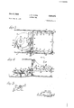
- Figure l is a plan section taken on lines l-l of Figure 2, showing the crank mechanism for reciprocating the line guide;
- Figure 2 is a sectional elevation showing the drive connections for the spool
- Figure 3 is an enlarged view of the line guide crank mechanism inposition to permit casting
- Figure 4 is an enlarged elevation of the line guide in casting position
- Figure 5 is a detail of the pawl and ratchet connection, the view being taken on lines 5-5 of Figure 4;
- Figure 6 is an end view of the reel looking from the right at Figure 2; I
- Figure '7 is a sectional elevation of a further form of the invention.
- Figure 8 is a sectional view taken on lines 8-8 of Figure 7.
- Figure 9 is a detail 8.
- Figure 10 is a further detail ofthe parts shown in Figure 9.
- the main frame or casting IQ is provided with a post I! ( Figure 2) of conventional designwhereby the casting may be detachably secured to a fishing rod l2 in accordance with well known methods now employed in securing reels on the usual type of reel seat with which the standard rod is customarily equipped.
- Welded or otherwise secured to frame it is a subframe l3 having a bearing l4.
- Frame it? has a hearing it in axial alignment with bearing I4 and spool rod I6 is suitably supported by these hearings for free rotation therein.
- rod I6 Secured to rod I6 is a helical gear ll meshing with gear l8 on a rod I9, the outer end of which is provided with a handle 20, whereby the parts may be rotated.
- the right hand end of rod l6 ( Figures 1 and 2) has keyed thereto spool 28 of double conical formation with end flanges 22 and aqsmaller central ring 23. Clockwise rotation of parts shown in Figure cross pattern and preventing of handle 28 (as viewed in Figure 2) will rotate spool 2i clockwise (as viewed in Figure 6) and as indicated by the arrow on shaft iii in Figure 2.
- gear 28 Secured to the left end of rod i6 is a gear which, through pinion 25, rod 2s and bevel pinion 22, rotates a bevel gear 23 in the direction of the arrow shown in Figure 2 about a stud 29 secured in a boss 3i of frame H3.
- the upper surface of gear 28 is provided w'th ratchet teeth St for engagement with a spring pressed pawl 32 pivoted to the underside of a cam 33.
- This cam is freely rotatable on stud 29 and when gear 28 is driven in the direction indicated by the arrow in Figure 2, cam 33 will be driven therewith through the ratchet connection in the direction of the arrow shown in Figure 1.
- this pawl and ratchet connection is shown on an enlarged scale.
- cam 33 is provided with a snail shaped cam slot 34 through which a pin 35 extends.
- This pin is normally locked n the end of the cam slot of least radius as indicated in Figure l, by a lever 36 which is pivoted at 31 to cam 33 and held in the position shown in Figure 3 by oppositely acting blade springs 33 carried by the cam 33.
- pin 35 extends through a slot 60 in a cross arm 41 which has a pair of transverse links 42 suitably guided for horizontal reciprocation in guides 43. Accordingly, as pin 35 travels in the circular path 38, it will reciprocate cross arm M and its integral links 62 between the full line and the dotted line positions indicated in Figure 1.
- each link 42 Pivotally connected at 44 end of each link 42 is an L-shaped member il i ( Figure 4.) which, during the normal reciprocation of links 42, will slide back and forth in a guide slot 55 which serves to retain the member in the upright position shown in Figures 2 and 4.
- line guide 48 having a bend at its center, whereby to guide the line during reeling operations.
- the line guide 46 is reciprocated between the full and dotted line positions indicated in Figure 1, with the line passing over the top of the guide onto the spool 2
- the ratio of the gearing is preferably chosen so that guide 15 makes slightly more or less than one reciprocation for each revolution of spool 2!, so that as a result with successive turns pattern.
- the central ring 23 assists greatly in properly starting the wind by guiding the line in a crissthe line from slipping along the spool.
- the particular proportions of the spool shown in Figure 2 are not intended to be limitations because the central ring may be varied in size in relation to the spool.
- the length of the spool of line is, of course, determined by the reciprocatory stroke of the shutt e arm it and by altering the size of cam 33 any desired capacity can be obtained.
- the device winds the line in a subsequently straight sided mass and, if desired, the end flanges 22 may be omitted.
- cam 33 When the fisherman is ready to cast, cam 33 is advanced to the position of Figure 1, that is, with links 42 and guide :36 in their extreme outer positions. In such position, the lever 36 en -cam closely spaced in a helical adjacent the free the line is laid on the spool move in the cam slot 34.
- the curved edge terminates in recess which partially encircles pin 5?, thereby serving to lock member 4 5 in casting position against accidental displacement during the casting operation. 0n the forward swing the line is drawn from the spool in the direction of its axis, being guided in a conical path as it feeds over cuter flange 22.
- the ratio of the gearing is preferably such that the guide d5 makes slightly more or less than one reoiprocation for each revolution of the spool M, with the result that the line is laid on the spool with successive turns in helical pattern.
- the guide ts will travel, for instance, from its extreme right left position and the line will be laid on the surface of the spool in a helical path for 186 of the spool.
- FIGS 7 through 10 show a modification of the invention in which a housing 9! has suitably journaled therein a shaft 9! driven by a handle 92 through gears 93 and 94. Secured to the shaft 9! is a spool 35, so that rotation of the handle is accompanied by turning of the spool. Suitable detenting wheel and dog members are provided at SS.
- Shaft I 93 has a reversing thread I65 out therein and a pin it; in block I06 rides in the thread grooves to reciprocate blocks I85 as the shaft turns.
- Block its embraces a rail It! ( Figure 7) and also straddles a rod m8, so as to reciprocate the rod therewith but leaving the rod free to turn in the block.
- line guide I69 which reciprocates to guide the line on the spool 55 as the latter is rotated.
- a fishing reel comprising a spool, a line guide having a line engaging loop therein movable back and forth along one side of the spool, actuating means for the guide operable to reciprocate it in a line between predetermined limits, manually operable means for controlling the movement of the guide to permit it to guide reciprocating means comprises a drive shaft, a pin rotatable therewith and located eccentrically with respect thereto and the manually operable means includes devices for increasing the eccentricity of the pin with respect to the shaft.
- a fishing reel a frame, a shaft mounted within said frame, a spool secured to said shaft, a reciprocable line guide mounted on said frame for reciprocation in the direction of the axis of said spool, a rotatable disk mounted within said frame and having a slot therein extending increasing distances from the center of rotation of said disk, a pin connected with said line guide and extending into and operable in said slot, means for releasably locking said pin in said slot at the point where the slot is closest to the center of rotation of the disk, means for releasing said pin, means for rotating said disk and said spool, and means for actuating said last-mentioned means.
- a fishing reel a frame, a shaft mounted within said frame, a spool secured to said shaft, a reciprocable line guide mounted on said frame for reciprocation in the direction of the axis of said spool, a rotatable disk mounted within said frame and having a slot therein extending increasing distances from the center of rotation of said disk, a pin connected with said line guide and extending intoand operable in said slot, means for releasably locking said pin in said slot at the point Where the slot is closest to the center of rotation of the disk, means for releasing said pin, means for rotating said disk and said spool, means for actuating said last-mentioned means, said first-mentioned means including a gear permanently connected to said shaft, and a train of gears releasably connected to said disk.
- a fishing reel a frame, a shaft mounted within said frame, a spool secured to said shaft, a reciprocable line guide mounted on said frame for reciprocation in the direction of the axis of said spool, a rotatable disk mounted within said frame and having a slot therein extending increasing distances from the center of rotation of said disk, a pin connected with said line guide and.
- said first-mentioned means including a gear permanently connected to said shaft, and a train of gears releasably connected to said disk, said train of gears having a dog and ratchet connection to said disk to permit said disk to rotate freely in one direction independent- 1y of the train of gears and to rotate with said train of gears in the opposite direction.
- a fishing reel a frame, a shaft mounted within said frame, a spool secured to said shaft, a reciprocaole line guide mounted on said frame for reciprocation in the direction of the axis of said spool, a rotatable disk mounted within said fram having a slot therein extending increasing distances from the center of rotation of said a pin connected with said line guide and extending into and operable in said slot, means for releasably locking said pin in said slot at t e point where the slot is closest to the center of rotation of the disk, means for releasing said pin, means for rotating said disk and said spool, means for actuating said last-mentioned means, said first-mentioned means including a gear permanently connected to said shaft, a train of gears releasably connected to said disk, said train of gears having a dog and ratchet connection to said disk to permit said disk to rotate freely in one direction independently of the train of gears and to rotate with said train of gears in the opposite
- a fishing reel a frame, a shaft mounted within said frame, a spool secured to said shaft, a reciprocable line guide mounted on said frame for reciprocation in the direction of the axis of said spool, a rotatable disk mounted within said frame and having a slot therein extending increasing distances from the center of rotation of said disk, a pin connected with said line guide and extending into and operable in said slot, means for releasably locking said pin in said slot at the point where the slot is closest to the center of rotation of the disk, means for releasing said pin, means for rotating said disk and said spool, means for actuating said last-mentioned means, said first-mentioned means including a gear permanently connected to said shaft, a train of gears releasably connected to said disk, said train of gears having a dog and ratchet connection to said disk to permit said disk to rotate freely in one direction independently of the train of gears and to rotate with said train of gears in the opposite direction, means
- a fishing reel comprising a spool, a line guide having a line engaging portion movable back and forth along one side of the spool, actuating means for the guide operable to reciprocate it in a line between predetermined limits, manually operable means for controlling the movement of the guide to permit it to travel various distances in one direction, means for moving the guide through the greater of said distances, and means effective upon the travel of said guide for said greater distance for shifting the guide to move the line engaging portion thereof out of line engaging position, said line guide being pivotally mounted and the shifting means including a cam operative to move said guide pivotally out of line-engaging position during a move ment of reciprocation of said guide.
- a fishing reel a spool shaft, a line receiving spool mounted on said shaft, means for rotating said spool, said spool comprising a pair of coaxial truncated conical surfaces having their portions of least diameter adjacent each other and joined together, means for feeding a single fishing line to said surfaces of said spool in a direction substantially normal to the axes of said truncated conical surfaces progressively longitudinal of the axes of said truncated conical surfaces successively in both longitudinal directions upon rotation of said spool in one direction, said line feeding means comprising a rcciprocable member reciprooable in a line substantially parallel to the axes of said truncated conical surfaces and said spool rotating means being constructed and arranged to impart one complete revolution to the spool while said reoiprocable member travels a distance at variance with a complete reciprocation substantially equal to the diameter of the line being wound upon the spool whereby the line is wound upon the irustro conical
Landscapes
- Life Sciences & Earth Sciences (AREA)
- Environmental Sciences (AREA)
- Animal Husbandry (AREA)
- Biodiversity & Conservation Biology (AREA)
Description
June 8, 1954 HAYEs 2,680,575
FISHING REEL Filed June 30, 1953 4 Sheets-Sheet l as 5o 35 az a1 54 10 I :5 I 26 21 I 50 26 I r--r--=- 29 F-' 'IT- I I l l INVENTOR JAMES H. HAYES BY M WOM ATTORNEYS H J. H. HAYES FISHING REEL June 8, 1954 4 Sheets-Sheet 2 Filed June 30, 1953 LI 5 a INVENTOR JAMES H. HAYE M June 8, 1954 J. H. HAYES 2,680,575 FISHING REEL Filed June 30, 1953 4 Sheets-Sheet 5 IINVENTOR JAMES H. HAYES ATTORNEYS J. H. HAYES FISHING REEL June 8, 1954 4 Sheets-Sheet 4 Filed June 30, 1953 INVENTOR. JAMES H. HAYES JW ATTORN line whenever it is Patented June 8, 1954 UNITED STATES ATENT OFFICIE 13 Claims.
This invention relates to fishing reels of the type wherein the line pays out generally axially of the spool, and is a continuation-in-part of the application of James H. Hayes, Serial No. 583,729, filed March 20,1945, now abandoned.
The principal object of the invention resides in the provision of novel line handling apparatus for winding line about a spool. To this end there is provided mechanism which is simple in structure, easily operable and highly efiicient in winding fishing line.
A specific object of the invention is to provide an improved line guide for a fishing reel and simplified operating devices therefor whereby the guide may speedily engage and disengage the desired to reel or cast.
A further object of the invention resides in the provision of novel mechanism for effecting the traverse of the line guide across a rotating space and devices for automatically swinging the line guide into an inactive position, so that the spool and line are free for casting purposes.
A still further object is to provide a structure whereby the line guide may be brought quickly active position by the simple turning of the spool winding handle or knob.
Another object resides in the provision of a line guide and control means therefor comprising an eccentric whose stroke determines the extent of reciprocation of the line guide and manual means for automatically changing the eccentricity of the movement to carry the line guide to an inactive position.
A further object is to provide a spool of improved design on which the line will be more satisfactorily wound.
In carrying out the invention, the novel reel is supported through an attaching bracket by means of which it may be secured to a rod, said bracket carrying a housing for the driving mechanism. The latter may include a chain of gears one of which is attached to a shaft extending laterally through the housing and carrying a crank handle for driving the chain of gears, which drives a spool supporting shaft positioned with its axis parallel to the rod.
From the chain of gears a unidirectional pawl and ratchet drive operates a crank mechanism to reciprocate a line guide alongside the spool, so that as the spool revolves the guide lays the line thereon with a spiral pattern determined by the relative rate of reciprocation of the guide with respect to the rate of turning of the spool.
. In casting, the line is designed to be fed freely from the spool and, as a preliminary, a button is provided to disable the crank mechanism and swing the guide out of the path of the line. Thereafter, rotation of the crank handle will automatically swing the guide back into line engaging position by restoring the disabled crank mechanism.
Other objects of the invention will be pointed out in the following description and claims and illustrated in the accompanying drawings, which disclose, by way of example, the principle of the invention and the best mode, which has been contemplated, of applying that principle.
In the drawings:
Figure l is a plan section taken on lines l-l of Figure 2, showing the crank mechanism for reciprocating the line guide;
Figure 2 is a sectional elevation showing the drive connections for the spool;
Figure 3 is an enlarged view of the line guide crank mechanism inposition to permit casting;
Figure 4 is an enlarged elevation of the line guide in casting position;
Figure 5 is a detail of the pawl and ratchet connection, the view being taken on lines 5-5 of Figure 4;
Figure 6 is an end view of the reel looking from the right at Figure 2; I
Figure '7 is a sectional elevation of a further form of the invention;
Figure 8 is a sectional view taken on lines 8-8 of Figure 7.
Figure 9 is a detail 8; and
Figure 10 is a further detail ofthe parts shown in Figure 9.
Referring to the embodiment of Figures 1 through 6, the main frame or casting IQ is provided with a post I! (Figure 2) of conventional designwhereby the casting may be detachably secured to a fishing rod l2 in accordance with well known methods now employed in securing reels on the usual type of reel seat with which the standard rod is customarily equipped. Welded or otherwise secured to frame it is a subframe l3 having a bearing l4. Frame it? has a hearing it in axial alignment with bearing I4 and spool rod I6 is suitably supported by these hearings for free rotation therein.
Secured to rod I6 is a helical gear ll meshing with gear l8 on a rod I9, the outer end of which is provided with a handle 20, whereby the parts may be rotated. The right hand end of rod l6 (Figures 1 and 2) has keyed thereto spool 28 of double conical formation with end flanges 22 and aqsmaller central ring 23. Clockwise rotation of parts shown in Figure cross pattern and preventing of handle 28 (as viewed in Figure 2) will rotate spool 2i clockwise (as viewed in Figure 6) and as indicated by the arrow on shaft iii in Figure 2.
Secured to the left end of rod i6 is a gear which, through pinion 25, rod 2s and bevel pinion 22, rotates a bevel gear 23 in the direction of the arrow shown in Figure 2 about a stud 29 secured in a boss 3i of frame H3. The upper surface of gear 28 is provided w'th ratchet teeth St for engagement with a spring pressed pawl 32 pivoted to the underside of a cam 33. This cam is freely rotatable on stud 29 and when gear 28 is driven in the direction indicated by the arrow in Figure 2, cam 33 will be driven therewith through the ratchet connection in the direction of the arrow shown in Figure 1. In Figure this pawl and ratchet connection is shown on an enlarged scale.
Referring to Figure 3, cam 33 is provided with a snail shaped cam slot 34 through which a pin 35 extends. This pin is normally locked n the end of the cam slot of least radius as indicated in Figure l, by a lever 36 which is pivoted at 31 to cam 33 and held in the position shown in Figure 3 by oppositely acting blade springs 33 carried by the cam 33.
With pin .35 so locked to cam 33, rotation of the cam will drive the pin in a circular path, whose radius is the least radius of the cam slot. This path is represented by the broken line 39 in Figure 3.
The upper end of pin 35 extends through a slot 60 in a cross arm 41 which has a pair of transverse links 42 suitably guided for horizontal reciprocation in guides 43. Accordingly, as pin 35 travels in the circular path 38, it will reciprocate cross arm M and its integral links 62 between the full line and the dotted line positions indicated in Figure 1.
Pivotally connected at 44 end of each link 42 is an L-shaped member il i (Figure 4.) which, during the normal reciprocation of links 42, will slide back and forth in a guide slot 55 which serves to retain the member in the upright position shown in Figures 2 and 4.
The two members it are connected by line guide 48 having a bend at its center, whereby to guide the line during reeling operations. Through the connections just traced, the line guide 46 is reciprocated between the full and dotted line positions indicated in Figure 1, with the line passing over the top of the guide onto the spool 2|.
The ratio of the gearing is preferably chosen so that guide 15 makes slightly more or less than one reciprocation for each revolution of spool 2!, so that as a result with successive turns pattern.
The central ring 23 assists greatly in properly starting the wind by guiding the line in a crissthe line from slipping along the spool. The particular proportions of the spool shown in Figure 2 are not intended to be limitations because the central ring may be varied in size in relation to the spool.
The length of the spool of line is, of course, determined by the reciprocatory stroke of the shutt e arm it and by altering the size of cam 33 any desired capacity can be obtained. The device winds the line in a subsequently straight sided mass and, if desired, the end flanges 22 may be omitted.
When the fisherman is ready to cast, cam 33 is advanced to the position of Figure 1, that is, with links 42 and guide :36 in their extreme outer positions. In such position, the lever 36 en -cam closely spaced in a helical adjacent the free the line is laid on the spool move in the cam slot 34.
33 lies in the arcuate path of a pin 50 in the end of an arm 5| pivoted at 52. This arm forms a bell crank with an arm 53 articulated with a plunger 54. By pressing button 55 inwardly, plunger 54 moves against the action of a restoring spring 56 and rocks bell cranks 5!, 53 to the dotted line position of Figure 1. As a result, pin 59 engages and rocks lever 36 out of locking engagement with pin 3'5, so that the .pin is free to The button 55 is pressed during the act of casting, so that pull on the line and the whip of the rod both assist in shifting the parts from their reeling to casting positions.
The lower link l?! (as viewed in Figure 1) is urged toward the right by a spring 49 whose right end is anchored to guide 53. Thus, when pin 35 is released, the tension of spring 49 will draw cross arm iii and pin 35 to the right, and will force clockwise rotation .of cam 33 from the position of Figure l to that of Figure 3 through the ca-mming action of pin 35 in slot 34. This clockwise rotation of cam 33 will cause reverse movement of the pawl and ratchet drive connection, so that following release of pin 35 handle 20 is turned in reverse direction sufficiently to permit cam -33 to turn Figure i shows the parts in this extreme or casting position and it is to be particularly observed that the line guide 6?; lies out of the path of movement of the line as it pays off of the spool during casting and the members 44 have rocked about their pivot points on links "32 preferably through an angle of substantially 180. This is effected as follows. As member 4a continues to the right from its normal line-guiding position shown in dotted outline, it rides out of guide slot iii? and its curved edge engages a fixed pin 5' 5 which coasts with the curved edge to turn the member to the full line position. The curved edge terminates in recess which partially encircles pin 5?, thereby serving to lock member 4 5 in casting position against accidental displacement during the casting operation. 0n the forward swing the line is drawn from the spool in the direction of its axis, being guided in a conical path as it feeds over cuter flange 22.
After the cast has been made, the parts are returned to initial reeling position by simply turning handle 25 in the reeling direction. This causes rotation of cam 33 counterclockwise as viewed in Figure whereby cam slot 34 acts on pin 35 to draw the pin toward the center of the cam until it snaps behind lever 36 where it remains until again released. Incidentally, links t? are drawn to the left and in so doing the left side of the depending arm of member ti (Fi ure 4) cams itself against pin 5? to return the member to its upright position where it enters guide slot 55. A pin 5 extending inwardly from member 4% will pass under a fixed ledge 59, which serves to guide the member until it is well into the guide slot As has heretofore been pointed out, the ratio of the gearing is preferably such that the guide d5 makes slightly more or less than one reoiprocation for each revolution of the spool M, with the result that the line is laid on the spool with successive turns in helical pattern. In other words, looking at Figure 1, when the spool 2i is rotated 180 the guide ts will travel, for instance, from its extreme right left position and the line will be laid on the surface of the spool in a helical path for 186 of the spool. When the guide it moves completely from the left to the right and the spool is roto its extreme gage the carnming surface tated another 180 the line will be laid on the surface of the spool in a helical path for the other 180 of the spool, and as the reciprocating movements of the guide are repeated these two 180 helical paths will be repeated so that the line will be built up on the spool as illustrated in Figure 1, and because of the difference in magnitude of the rotation of the spool and the simultaneous reciprocation of the guide, the line will be laid side by side on the spool in what will amount to substantially a cylindrical form so that when casting the line will be substantially free of any friction or otherwise stated will be laid on the spool, and therefore will pay off of the spool with no substantial resistance to its paying off. In this way, upon one reciprocation of the guide 5 and one revolution of the spool 2| the line will pass from one side of the spool to the diametrically opposite side of the spool in a helical path and then will pass from the latter back to the former side in a helical path, thus completing the 360 winding.
Figures 7 through 10 show a modification of the invention in which a housing 9!) has suitably journaled therein a shaft 9! driven by a handle 92 through gears 93 and 94. Secured to the shaft 9! is a spool 35, so that rotation of the handle is accompanied by turning of the spool. Suitable detenting wheel and dog members are provided at SS.
Secured to shaft 9| is a lever 9i carrying spring urged dogs 98 which engage in internal ratchet teeth of a member 99 loose on shaft 9!. This member has external gear teeth Hill which through an idler fill drive a gear It? secured to a shaft 5 83. Thus, when shaft 9! is driven clockwise as viewed in Figure 7, shaft I33 is driven in the same direction.
Shaft I 93 has a reversing thread I65 out therein and a pin it; in block I06 rides in the thread grooves to reciprocate blocks I85 as the shaft turns. Block its embraces a rail It! (Figure 7) and also straddles a rod m8, so as to reciprocate the rod therewith but leaving the rod free to turn in the block.
At the left end of rod 5% is secured line guide I69 which reciprocates to guide the line on the spool 55 as the latter is rotated.
When it is desired to cast, line guide its is moved to its extreme left hand position as indicated in Figure 8 and button H8 is pressed against the action of its spring Ill. The button pushes the tapered end of a plunger H2 beneath a dog I E3 to raise the latter out of a notch I M in sleeve H5. This sleeve serves as a guide for rod H38, which latter has a pin H6 riding in a slot H! of the sleeve. During reeling operations sleeve H5 is biased by a spring H8 against dog H3 to maintain slot if? in the positions shown in Figures 8 and 1:), where it prevents shaft H38 from turning.
When, however, button He is operated, dog H3 is removed and spring i 58 will turn the sleeve clockwise as viewed in Figure 10. This turning is aided and rendered positive by the engagement of the end of plunger H2 with a cam sur face H8, so that line guide see is thereby rocked to the dotted line position of Figure 7.
To restore the parts to reeling position, it is simply necessary to rotate handle 92 which will result in drawing line guide we to the right as viewed in Figure 8 and as the guide so moves its camming surface adjacent the rod Hi8 will en- IZB which is stationary with the frame 90, and as a result it will be in one direction,
rocked thereby back to its original position. As it passes over hump H3, it rocks a little beyond the full line position of Figure 10' and thereby rocks its shaft I08 and pin I I6 and also sleeve H5 enough to insure that dog H3 will snap back into latching engagement with notch H4.
While there have been shown and described and pointed out the fundamental novel features of the invention as applied to two embodiments, it will be understood that various omissions and substitutions and changes in the form and details of the device illustrated and in its operathose skilled in the art with- I claim:
1. A fishing reel comprising a spool, a line guide having a line engaging loop therein movable back and forth along one side of the spool, actuating means for the guide operable to reciprocate it in a line between predetermined limits, manually operable means for controlling the movement of the guide to permit it to guide reciprocating means comprises a drive shaft, a pin rotatable therewith and located eccentrically with respect thereto and the manually operable means includes devices for increasing the eccentricity of the pin with respect to the shaft.
4. The invention set forth in claim 2 in which the line guide reciprocating I 5. In a fishing reel, a frame, a shaft mounted. Within said frame, a spool secured to said shaft creasing distances from the center of rotation of said disk, a pin connected with said line guide and extending into and operable in said slot, means for releasably locking said pin in said slot at the point where the slot is closest to the center of rotation of the disk, means for releasing said pin, and means for rotating said 'disk and said spool.
' 6. In a fishing reel, a frame, a shaft mounted within said frame, a spool secured to said shaft, a reciprocable line guide mounted on said frame for reciprocation in the direction of the axis of said spool, a rotatable disk mounted within said frame and having a slot therein extending increasing distances from the center of rotation of said disk, a pin connected with said line guide and extending into and operable in said slot, means for releasably locking said pin in said slot at the point where the slot is closest to the center of rotation of the disk, means for releasing said pin, means for rotating said disk and said spool, and means for actuating said last-mentioned means.
7. In a fishing reel, a frame, a shaft mounted within said frame, a spool secured to said shaft, a reciprocable line guide mounted on said frame for reciprocation in the direction of the axis of said spool, a rotatable disk mounted within said frame and having a slot therein extending increasing distances from the center of rotation of said disk, a pin connected with said line guide and extending intoand operable in said slot, means for releasably locking said pin in said slot at the point Where the slot is closest to the center of rotation of the disk, means for releasing said pin, means for rotating said disk and said spool, means for actuating said last-mentioned means, said first-mentioned means including a gear permanently connected to said shaft, and a train of gears releasably connected to said disk.
8. In a fishing reel, a frame, a shaft mounted within said frame, a spool secured to said shaft, a reciprocable line guide mounted on said frame for reciprocation in the direction of the axis of said spool, a rotatable disk mounted within said frame and having a slot therein extending increasing distances from the center of rotation of said disk, a pin connected with said line guide and. extending into and operable in said slot, means for releasably locking said pin in said slot at the point where the slot is closest to the center of rotation of the disk, means for releasing said pin, means for rotating said disk and said spool, means for actuating said lastmentioned means, said first-mentioned means including a gear permanently connected to said shaft, and a train of gears releasably connected to said disk, said train of gears having a dog and ratchet connection to said disk to permit said disk to rotate freely in one direction independent- 1y of the train of gears and to rotate with said train of gears in the opposite direction.
9. In a fishing reel, a frame, a shaft mounted within said frame, a spool secured to said shaft, a reciprocaole line guide mounted on said frame for reciprocation in the direction of the axis of said spool, a rotatable disk mounted within said fram having a slot therein extending increasing distances from the center of rotation of said a pin connected with said line guide and extending into and operable in said slot, means for releasably locking said pin in said slot at t e point where the slot is closest to the center of rotation of the disk, means for releasing said pin, means for rotating said disk and said spool, means for actuating said last-mentioned means, said first-mentioned means including a gear permanently connected to said shaft, a train of gears releasably connected to said disk, said train of gears having a dog and ratchet connection to said disk to permit said disk to rotate freely in one direction independently of the train of gears and to rotate with said train of gears in the opposite direction, for releasing said dog from said ratchet, and automatic means connected to and operable through said guide to move said guide in one direction to rotate said disk to cause said pin to advance in said slot from the point thereof closest to the center of rotation of said disk toward the opposite end of said slot.
10. In a fishing reel, a frame, a shaft mounted within said frame, a spool secured to said shaft, a reciprocable line guide mounted on said frame for reciprocation in the direction of the axis of said spool, a rotatable disk mounted within said frame and having a slot therein extending increasing distances from the center of rotation of said disk, a pin connected with said line guide and extending into and operable in said slot, means for releasably locking said pin in said slot at the point where the slot is closest to the center of rotation of the disk, means for releasing said pin, means for rotating said disk and said spool, means for actuating said last-mentioned means, said first-mentioned means including a gear permanently connected to said shaft, a train of gears releasably connected to said disk, said train of gears having a dog and ratchet connection to said disk to permit said disk to rotate freely in one direction independently of the train of gears and to rotate with said train of gears in the opposite direction, means for releasing said dog from said ratchet, automatic means connected to and operable through said guide to move said guide in one direction to rotate said disk to cause said pin to advance in said slot from the point thereof closest to the center of rotation of said disk toward the opposite end of said slot, said guide having an articulated portion adapted to swing over the end of the spool upon the aforesaid traversing movement of said pin within said slot, and means for causing such swinging movement of said articulated portion upon the release of said pin by its locking means.
11. A fishing reel comprising a spool, a line guide having a line engaging portion movable back and forth along one side of the spool, actuating means for the guide operable to reciprocate it in a line between predetermined limits, manually operable means for controlling the movement of the guide to permit it to travel various distances in one direction, means for moving the guide through the greater of said distances, and means effective upon the travel of said guide for said greater distance for shifting the guide to move the line engaging portion thereof out of line engaging position, said line guide being pivotally mounted and the shifting means including a cam operative to move said guide pivotally out of line-engaging position during a move ment of reciprocation of said guide.
12. In a fishing reel, a spool shaft, a line receiving spool mounted on said shaft, means for rotating said spool, said spool comprising a pair of coaxial truncated conical surfaces having their portions of least diameter adjacent each other and joined together, means for feeding a single fishing line to said surfaces of said spool in a direction substantially normal to the axes of said truncated conical surfaces progressively longitudinal of the axes of said truncated conical surfaces successively in both longitudinal directions upon rotation of said spool in one direction, said line feeding means comprising a rcciprocable member reciprooable in a line substantially parallel to the axes of said truncated conical surfaces and said spool rotating means being constructed and arranged to impart one complete revolution to the spool while said reoiprocable member travels a distance at variance with a complete reciprocation substantially equal to the diameter of the line being wound upon the spool whereby the line is wound upon the irustro conical surfaces of the spool in a helical path and is built in a substantially cylindrical manner having its axis substantially coincident with those of the frustro conical surfaces.
13. The combination of elements recited in claim 12 wherein an annular line starting enlargement is interposed between the adjacent ends of said frustro conical surfaces.
References Cited in the file of this patent UNITED STATES PATENTS Number Name Date 817,987 Richardson Apr. 17, 1906 905,329 Krause et a1 Dec. 1, 1908 Number Name Date Clickner Dec. 30, 1924 Stanley Apr. 22, 1930 Coxe Aug. 5, 1941 Gaire Mar. 23, 1943 Coxe Mar. 14, 1944 King Nov. 28, 1944 Coleman June 12, 1945 Worden Sept. 30, 1947 FOREIGN PATENTS Country Date Great Britain of 1910 Great Britain of 1907 Great Britain Dec. 24, 1931 France Feb. 2, 1938 France Oct. 19, 1942 France Aug. 23, 1943 Norway Dec. 2, 1940
Priority Applications (1)
| Application Number | Priority Date | Filing Date | Title |
|---|---|---|---|
| US365098A US2680575A (en) | 1953-06-30 | 1953-06-30 | Fishing reel |
Applications Claiming Priority (1)
| Application Number | Priority Date | Filing Date | Title |
|---|---|---|---|
| US365098A US2680575A (en) | 1953-06-30 | 1953-06-30 | Fishing reel |
Publications (1)
| Publication Number | Publication Date |
|---|---|
| US2680575A true US2680575A (en) | 1954-06-08 |
Family
ID=23437463
Family Applications (1)
| Application Number | Title | Priority Date | Filing Date |
|---|---|---|---|
| US365098A Expired - Lifetime US2680575A (en) | 1953-06-30 | 1953-06-30 | Fishing reel |
Country Status (1)
| Country | Link |
|---|---|
| US (1) | US2680575A (en) |
Cited By (5)
| Publication number | Priority date | Publication date | Assignee | Title |
|---|---|---|---|---|
| US3085766A (en) * | 1959-03-11 | 1963-04-16 | Fishing Tackle Company Of Amer | Spinning type fishing reel |
| US3224703A (en) * | 1962-10-25 | 1965-12-21 | True Temper Corp | Spool oscillating mechanism for spinning reel |
| US3876162A (en) * | 1972-10-10 | 1975-04-08 | Choon S Chun | Golf practice apparatus having an automatic golf ball retriever |
| US6264125B1 (en) | 1999-12-09 | 2001-07-24 | Brunswick Corporation | Asymmetric oscillation mechanism for a spinning reel |
| WO2014178742A1 (en) * | 2013-04-30 | 2014-11-06 | Dragan Bakrač | Standard reel without a rotor |
Citations (16)
| Publication number | Priority date | Publication date | Assignee | Title |
|---|---|---|---|---|
| US817987A (en) * | 1904-08-02 | 1906-04-17 | America Company | Fish-line reel. |
| GB190722597A (en) * | 1907-10-14 | 1908-06-11 | Michael Holroyd Smith | Improvements in Line Winders used in Angling |
| US905329A (en) * | 1908-04-20 | 1908-12-01 | Hans A Krause | Line-winding mechanism. |
| GB191015756A (en) * | 1910-07-01 | 1911-03-23 | Samuel Mawson | Improvements in Casting Reels. |
| US1521229A (en) * | 1923-01-13 | 1924-12-30 | Shakespeare Co | Fishing reel |
| US1755195A (en) * | 1926-10-30 | 1930-04-22 | Stanley Walter | Fishing reel |
| GB363597A (en) * | 1931-04-29 | 1931-12-24 | John Stuart Daniels | Improvements in line casting or paying out apparatus |
| FR828000A (en) * | 1936-10-19 | 1938-05-06 | Angling reel | |
| US2251782A (en) * | 1936-11-04 | 1941-08-05 | Bronson Reel Company | Fishing reel |
| FR878594A (en) * | 1942-01-20 | 1943-01-25 | Spinning reel | |
| US2314616A (en) * | 1940-01-13 | 1943-03-23 | Gaire Paul Edmond | Fishing reel |
| FR887877A (en) * | 1942-07-04 | 1943-11-25 | Fishing reel | |
| US2344132A (en) * | 1936-11-04 | 1944-03-14 | Bronson Reel Company | Fishing reel spool |
| US2363533A (en) * | 1941-09-20 | 1944-11-28 | Frank A King | Reeling mechanism |
| US2377996A (en) * | 1944-05-24 | 1945-06-12 | Philip G Coleman | Level-wind mechanism |
| US2428324A (en) * | 1946-07-15 | 1947-09-30 | R B Worden | Stripper reel |
-
1953
- 1953-06-30 US US365098A patent/US2680575A/en not_active Expired - Lifetime
Patent Citations (16)
| Publication number | Priority date | Publication date | Assignee | Title |
|---|---|---|---|---|
| US817987A (en) * | 1904-08-02 | 1906-04-17 | America Company | Fish-line reel. |
| GB190722597A (en) * | 1907-10-14 | 1908-06-11 | Michael Holroyd Smith | Improvements in Line Winders used in Angling |
| US905329A (en) * | 1908-04-20 | 1908-12-01 | Hans A Krause | Line-winding mechanism. |
| GB191015756A (en) * | 1910-07-01 | 1911-03-23 | Samuel Mawson | Improvements in Casting Reels. |
| US1521229A (en) * | 1923-01-13 | 1924-12-30 | Shakespeare Co | Fishing reel |
| US1755195A (en) * | 1926-10-30 | 1930-04-22 | Stanley Walter | Fishing reel |
| GB363597A (en) * | 1931-04-29 | 1931-12-24 | John Stuart Daniels | Improvements in line casting or paying out apparatus |
| FR828000A (en) * | 1936-10-19 | 1938-05-06 | Angling reel | |
| US2251782A (en) * | 1936-11-04 | 1941-08-05 | Bronson Reel Company | Fishing reel |
| US2344132A (en) * | 1936-11-04 | 1944-03-14 | Bronson Reel Company | Fishing reel spool |
| US2314616A (en) * | 1940-01-13 | 1943-03-23 | Gaire Paul Edmond | Fishing reel |
| US2363533A (en) * | 1941-09-20 | 1944-11-28 | Frank A King | Reeling mechanism |
| FR878594A (en) * | 1942-01-20 | 1943-01-25 | Spinning reel | |
| FR887877A (en) * | 1942-07-04 | 1943-11-25 | Fishing reel | |
| US2377996A (en) * | 1944-05-24 | 1945-06-12 | Philip G Coleman | Level-wind mechanism |
| US2428324A (en) * | 1946-07-15 | 1947-09-30 | R B Worden | Stripper reel |
Cited By (5)
| Publication number | Priority date | Publication date | Assignee | Title |
|---|---|---|---|---|
| US3085766A (en) * | 1959-03-11 | 1963-04-16 | Fishing Tackle Company Of Amer | Spinning type fishing reel |
| US3224703A (en) * | 1962-10-25 | 1965-12-21 | True Temper Corp | Spool oscillating mechanism for spinning reel |
| US3876162A (en) * | 1972-10-10 | 1975-04-08 | Choon S Chun | Golf practice apparatus having an automatic golf ball retriever |
| US6264125B1 (en) | 1999-12-09 | 2001-07-24 | Brunswick Corporation | Asymmetric oscillation mechanism for a spinning reel |
| WO2014178742A1 (en) * | 2013-04-30 | 2014-11-06 | Dragan Bakrač | Standard reel without a rotor |
Similar Documents
| Publication | Publication Date | Title |
|---|---|---|
| US2613468A (en) | Fishing reel | |
| US1393286A (en) | Reeling-machine | |
| US2680575A (en) | Fishing reel | |
| US2179413A (en) | Fishing rod and reel | |
| US2615647A (en) | Fishing line reel | |
| US2676769A (en) | Spinning reel | |
| US3032290A (en) | Automatic spinning reel | |
| US2639870A (en) | Line spooling device for fishing reels | |
| US2512357A (en) | Fishing reel | |
| US1867688A (en) | Traverse mechanism for reeling machines | |
| US2461884A (en) | Level wind for fishing reels | |
| US2377996A (en) | Level-wind mechanism | |
| US2711046A (en) | Fishing reel | |
| US2623349A (en) | Automatic winding timepiece | |
| US2641418A (en) | Fishing reel | |
| US2623704A (en) | Fishing reel for fishing rods | |
| US3258218A (en) | Intermittent drive for a fishing reel | |
| US2990130A (en) | Spinning reel | |
| US4154414A (en) | Open face spinning reel with notched flyer | |
| US3464646A (en) | Level winding mechanism for fishing reels | |
| US1535036A (en) | Spinning machine | |
| US1988067A (en) | Driving gear for artificial silk bobbin-spinning machines | |
| US2290268A (en) | Automatic fishing reel | |
| US3036789A (en) | Spinning reel | |
| US1728448A (en) | Reciprocating guide motions for directing yarn or other material to winding bobbins or the like |