US2680409A - Centrifugal pump - Google Patents
Centrifugal pump Download PDFInfo
- Publication number
- US2680409A US2680409A US156802A US15680250A US2680409A US 2680409 A US2680409 A US 2680409A US 156802 A US156802 A US 156802A US 15680250 A US15680250 A US 15680250A US 2680409 A US2680409 A US 2680409A
- Authority
- US
- United States
- Prior art keywords
- impeller
- pump
- casing
- head
- rotation
- Prior art date
- Legal status (The legal status is an assumption and is not a legal conclusion. Google has not performed a legal analysis and makes no representation as to the accuracy of the status listed.)
- Expired - Lifetime
Links
- XLYOFNOQVPJJNP-UHFFFAOYSA-N water Substances O XLYOFNOQVPJJNP-UHFFFAOYSA-N 0.000 description 6
- 230000003247 decreasing effect Effects 0.000 description 4
- 238000005086 pumping Methods 0.000 description 4
- 230000007423 decrease Effects 0.000 description 2
- 239000012530 fluid Substances 0.000 description 2
- 239000007788 liquid Substances 0.000 description 2
- 238000012986 modification Methods 0.000 description 2
- 230000004048 modification Effects 0.000 description 2
- 238000005406 washing Methods 0.000 description 2
- 230000000694 effects Effects 0.000 description 1
- 230000002401 inhibitory effect Effects 0.000 description 1
- 229920000136 polysorbate Polymers 0.000 description 1
- 230000002250 progressing effect Effects 0.000 description 1
- 230000000630 rising effect Effects 0.000 description 1
- 235000002020 sage Nutrition 0.000 description 1
Images

Classifications
-
- F—MECHANICAL ENGINEERING; LIGHTING; HEATING; WEAPONS; BLASTING
- F04—POSITIVE - DISPLACEMENT MACHINES FOR LIQUIDS; PUMPS FOR LIQUIDS OR ELASTIC FLUIDS
- F04D—NON-POSITIVE-DISPLACEMENT PUMPS
- F04D29/00—Details, component parts, or accessories
- F04D29/40—Casings; Connections of working fluid
- F04D29/42—Casings; Connections of working fluid for radial or helico-centrifugal pumps
- F04D29/44—Fluid-guiding means, e.g. diffusers
- F04D29/445—Fluid-guiding means, e.g. diffusers especially adapted for liquid pumps
Definitions
- my invention is directed also to the provision of an impeller pump having unusual directional characteristics.
- my invention when applied in one casing arrangement will provide a pump which will generate positive pumping head of large magnitude for one direction of rotation of the impeller and substantially no pumping head for reverse rotation of the im peller.
- a pump casing of relatively conventional shape with a novel inlet system comprising a curving channel which is concentric with the impeller and follows a predetermined are on a radius not less than that of the root circle of the impeller blades.
- a wall or walls of the channel are arranged to effect a relatively uniform decrease in the cross-sectional area of the channel, the mouth thereof having the greatest area.
- the total maximum head produced in the unidirectional pump embodying my invention may be made up of nearly equal parts of centrifugal head and velocity head, so that when the pump is operated in the forward direction the velocity head is added to the centrifugal head, but when the pump is operated in reverse the velocity head subtracts from the centrifugal head to give practically no resultant head.
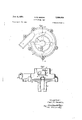
- Fig. l is a top plan view of a uni-directional pump embodying my invention, the arrangement and relationship of the impeller blades relative to the pump casing being indicated in dotted line;
- Fig. 2 is a side elevation of the pump of Fig. 1 with a portion of the casing wall broken away to show the commencement of the directional inlet;
- Fig. 3 is a sectional elevation taken on the lines 3--3 of Fig. 1.
- an impeller pump embodying my invention comprises a main casing section I and a base plate 2 which collectively define a chamber 3 within which operates the impeller 4.
- the said impeller comprises four rectangularly associated blades 5 rising from a circular web 5.
- the impeller is mounted on a shaft 1 suitably journaled in a casing neck 8 within an appropriate bearing 9 disposed therein.
- a seal of conventional pattern prevents escape of liquid along the pump shaft. It is to be understood that the impeller shaft is arranged to be rotated by any suitable driving means.
- the inlet to the pump casing comprises a pas sage H having a mouth 12 the area of which is substantially that of the pump discharge l 4.
- the roof l5 of the inlet passage slopes downwardly toward the top body wall Q6 of the casing I and follows the counterclockwise direction of rotation of the impeller during its pumping operation. As appears from Fig. 1, the minimum radius of the passage II is greater than the root circle of the impeller blades 5.
- the collar I l the wall of which provides an outer wall of the passage H, provide means for amxing the pump to a conduit, tank or vat from which liquid is to be pumped,
- thepump will be used as a drainage pump for a clothes washing machine in which event the collar ll will be clamped or otherwise secured to the neck of a drainage opening in the washing machine tub.
- Collar I! also provides a structure within which a conventional strainer or vortex inhibiting bafiie or screen (not shown) may be mounted.
- the outlet connection M of the casing extends substantially tangentially therefrom.
- the area of the directional inlet ll considering the bottom surface of the casing wall I 6 asrepresenting the bottom of the inlet passage, is greatest in the area of small casing radius and smallest at 'the area of greatest casing radius, said lastnamed area comprehending the entry to the outflow connection 14.
- the pump inlet I2 is somewhat more than ninety degrees removed from the inlet of the discharge connection M. This departure from the pre viously noted relationship of an N in which N is the number of blades in the impeller takes into consideration the thickness of the impeller blades in the area of the mouth of the inlet.
- the terminal line I3 of the passage H is preferably normal .to the axis of the outlet i l.
- the casing of the Fig. 1 embodiment is scroll shaped pursuant to conventional centrifugal tween the blades at a point radially beyond the impeller hub, distributing the inflowing water through an arc, and establishing a cross-sectional area of the inflow passage which decreases as the casing area beyond the blade tips increases.
- the above relationships appear to eiiect a dragging action exerted on the water in the inlet channel by the water being carried along by the impeller.
- the dragging action produces a head at the mouth .of the inlet channel which may be less than the head occurring at the center of the impeller chamber if the impeller is rotated forward or which may be greater than the head occurring at the center of the impeller chamber if the impeller is driven in reverse.
- An unidirectional flow pump including a multi-blade rotatable impeller, a casin for said impeller defining an involute pump chamber increasing in radius in positive direction of rotation around the axis of said impeller, an outlet from said casing extending from said chamber at its maximum radius, and directional inlet means into said chamber providing positive velocity head in the positive rotational direction, said means comprising an annular wall concentric with said impeller and extending outwardly from said casing, an arcuate passage enclosed by said annular wall and extending around the axis of said impeller displaced axially from and communicating with said chamber throughout, said passage decreasing in cross-sectional flow area in the positive direction of rotation from a mouth positioned with respect to said casing at an area of small chamber radius to a terminus at maximum cham bar radius, whereby rotation of said impeller in the positive direction results in a positive head While reverse rotation results in substantially no head.
- a pump providing fluid flow only upon positive direction of rotation comprising a base plate, a multi-blade impeller mounted for rotation with respect to said base plate, means for rotating said impeller, a cover cooperating with said base plate to form a scroll casin enclosing said impeller and having a minimum internal radius with respect to the impeller rotational axis slightly exceeding the radius of said impeller and an increasing radius in the positive direction of rotation, means defining an outlet passage from within said casing at its maximum radius extending tangentially with respect to said casing, and means defining a directional inlet to said casing through said cover, said last mentioned means comprising an exterior annular wall portion extending outwardly from said cover concentric with the impeller axis, an arcuate and concentric inner wall of minimum radius greater than the radius of the root circle of said impeller blades, and a roof portion interconnecting said exterior and inner walls inclined inwardly toward said casmg in the positive direction of rotation, said roof and walls definin a passage commencing with a mouth of flow
- a pump providing fluid fiow only upon positive direction of rotation including a multi-blade impeller, a casing .for said impeller defining an involute pump chamber increasing in radius in the positive direction of rotation around the axis of said impeller, an outlet from said casing extending from said chamber at its maximum radius, and directional inlet means providing positive velocity head in the positive rotational directlon, said directional inlet means comprising an exterior wall in the form of an annular collar extending outwardly from said casing and concentric with the impeller axis, an inner .arcuate wall concentric with said exterior wall and of a minimum radius exceeding the root circle radius of said impeller, and a roof interconnecting said exterior and inner walls inclined toward said chamber in the positive direction of rotation to define an inlet passage commencing with a mouth of cross-sectional area equivalent .to .said outlet and decreasing in cross-sectional area in the positive direction of rotation.
Landscapes
- Engineering & Computer Science (AREA)
- Mechanical Engineering (AREA)
- General Engineering & Computer Science (AREA)
- Structures Of Non-Positive Displacement Pumps (AREA)
Description
June 8, 1954 Filed April is, 1950 c. R. SEBENS CENTRIFUGAL PUMP 2 Sheets-Sheet 1 Inventof: Carl R. Sebens,
His Abbot-neg.
June 8, 1954 c. R. SEBENS ,680,409 CENTRIFUGAL PUMP Filed April 19, 1950 2 Sheets-Sheet 2 Inventor: Carl R. Sebens,
b I I (I I His Attor-rwg.
Patented June 8, 1954 CENTRIFUGAL PUMP Carl R. Sebens, Bridgeport, Conn., assignor to General Electric Company, a corporation of New York Application April 19, 1950, Serial No. 156,802
my invention is directed also to the provision of an impeller pump having unusual directional characteristics. For example, my invention when applied in one casing arrangement will provide a pump which will generate positive pumping head of large magnitude for one direction of rotation of the impeller and substantially no pumping head for reverse rotation of the im peller.
In accomplishing these objectives I equip a pump casing of relatively conventional shape with a novel inlet system comprising a curving channel which is concentric with the impeller and follows a predetermined are on a radius not less than that of the root circle of the impeller blades. A wall or walls of the channel are arranged to effect a relatively uniform decrease in the cross-sectional area of the channel, the mouth thereof having the greatest area. I have found that the best results obtain when the terminus of the inlet channel is within the area of maximum radius of the casing scroll, and the mouth of the channel is displaced from the pump casing discharge in approximately the angular relation velocity head adds to the centrifugal head to produce the total head, but when the pump is operated in reverse the velocity head subtracts from the centrifugal head and results in a decreased total head. The total maximum head produced in the unidirectional pump embodying my invention may be made up of nearly equal parts of centrifugal head and velocity head, so that when the pump is operated in the forward direction the velocity head is added to the centrifugal head, but when the pump is operated in reverse the velocity head subtracts from the centrifugal head to give practically no resultant head.
The foregoing discussion of performance will 3 ClaimS.' (Cl. 103103) be better understood from a comparison of test results. A single-direction pump embodying my pumping head amounting to six inches of water pressure for opposite rotation. In contrast, a conventionaI center-entrance impeller pump of similar size and mechanical characteristics produced a positive pressure of about five and onehalf feet of water for one direction of rotation and a positive head of about one and one-half feet of water for reverse rotation.
In the accompanying drawings Fig. l is a top plan view of a uni-directional pump embodying my invention, the arrangement and relationship of the impeller blades relative to the pump casing being indicated in dotted line; Fig. 2 is a side elevation of the pump of Fig. 1 with a portion of the casing wall broken away to show the commencement of the directional inlet; and Fig. 3 is a sectional elevation taken on the lines 3--3 of Fig. 1.
Referring initially to Figs. 1 and 3, an impeller pump embodying my invention comprises a main casing section I and a base plate 2 which collectively define a chamber 3 within which operates the impeller 4. Illustratively the said impeller comprises four rectangularly associated blades 5 rising from a circular web 5. The impeller is mounted on a shaft 1 suitably journaled in a casing neck 8 within an appropriate bearing 9 disposed therein. A seal of conventional pattern prevents escape of liquid along the pump shaft. It is to be understood that the impeller shaft is arranged to be rotated by any suitable driving means.
The inlet to the pump casing comprises a pas sage H having a mouth 12 the area of which is substantially that of the pump discharge l 4. The roof l5 of the inlet passage slopes downwardly toward the top body wall Q6 of the casing I and follows the counterclockwise direction of rotation of the impeller during its pumping operation. As appears from Fig. 1, the minimum radius of the passage II is greater than the root circle of the impeller blades 5. The collar I l, the wall of which provides an outer wall of the passage H, provide means for amxing the pump to a conduit, tank or vat from which liquid is to be pumped, For example, it is contemplated that thepump will be used as a drainage pump for a clothes washing machine in which event the collar ll will be clamped or otherwise secured to the neck of a drainage opening in the washing machine tub. Collar I! also provides a structure within which a conventional strainer or vortex inhibiting bafiie or screen (not shown) may be mounted.
The outlet connection M of the casing extends substantially tangentially therefrom. As is apparent from a comparison of Figs. 1 and 2, the area of the directional inlet ll, considering the bottom surface of the casing wall I 6 asrepresenting the bottom of the inlet passage, is greatest in the area of small casing radius and smallest at 'the area of greatest casing radius, said lastnamed area comprehending the entry to the outflow connection 14. It will be noted also that the pump inlet I2 is somewhat more than ninety degrees removed from the inlet of the discharge connection M. This departure from the pre viously noted relationship of an N in which N is the number of blades in the impeller takes into consideration the thickness of the impeller blades in the area of the mouth of the inlet. The terminal line I3 of the passage H is preferably normal .to the axis of the outlet i l.
The casing of the Fig. 1 embodiment is scroll shaped pursuant to conventional centrifugal tween the blades at a point radially beyond the impeller hub, distributing the inflowing water through an arc, and establishing a cross-sectional area of the inflow passage which decreases as the casing area beyond the blade tips increases. The above relationships appear to eiiect a dragging action exerted on the water in the inlet channel by the water being carried along by the impeller. The dragging action produces a head at the mouth .of the inlet channel which may be less than the head occurring at the center of the impeller chamber if the impeller is rotated forward or which may be greater than the head occurring at the center of the impeller chamber if the impeller is driven in reverse.
The disposition of the inlet 12 ninety degrees or more from the pump exhaust .(in a four-bladed impeller pump) prevents interference between the action occurring at, the inlet and the action occurring at the outlet of the impeller chamber.
While I have shown a particular embodiment of my invention, it will be understood, of course, that I do not wish to be limited thereto since many modifications may be made; and I therefore contemplate by the appended claims to cover any such modifications as fall within the true spirit and scope of my invention.
What I claim as new and desire to secure by Letters Patent of the United States is:
1. An unidirectional flow pump including a multi-blade rotatable impeller, a casin for said impeller defining an involute pump chamber increasing in radius in positive direction of rotation around the axis of said impeller, an outlet from said casing extending from said chamber at its maximum radius, and directional inlet means into said chamber providing positive velocity head in the positive rotational direction, said means comprising an annular wall concentric with said impeller and extending outwardly from said casing, an arcuate passage enclosed by said annular wall and extending around the axis of said impeller displaced axially from and communicating with said chamber throughout, said passage decreasing in cross-sectional flow area in the positive direction of rotation from a mouth positioned with respect to said casing at an area of small chamber radius to a terminus at maximum cham bar radius, whereby rotation of said impeller in the positive direction results in a positive head While reverse rotation results in substantially no head.
2. A pump providing fluid flow only upon positive direction of rotation comprising a base plate, a multi-blade impeller mounted for rotation with respect to said base plate, means for rotating said impeller, a cover cooperating with said base plate to form a scroll casin enclosing said impeller and having a minimum internal radius with respect to the impeller rotational axis slightly exceeding the radius of said impeller and an increasing radius in the positive direction of rotation, means defining an outlet passage from within said casing at its maximum radius extending tangentially with respect to said casing, and means defining a directional inlet to said casing through said cover, said last mentioned means comprising an exterior annular wall portion extending outwardly from said cover concentric with the impeller axis, an arcuate and concentric inner wall of minimum radius greater than the radius of the root circle of said impeller blades, and a roof portion interconnecting said exterior and inner walls inclined inwardly toward said casmg in the positive direction of rotation, said roof and walls definin a passage commencing with a mouth of flow area substantially equal to the .flow area of said outlet passage and located circumierentially in the positive direction of rotation from said outlet passage .by at least the are between adjacent impeller blades, said roof portion sloping inwardly toward said impeller from said mouth to a terminus extending radially across said passage and having minimum clearance with respect to said impeller, the terminus of said passage being located substantially at said casing outlet passage, whereby fiuid enter- 1 ing through said directional inlet is given an initial positive rotational velocity and is forced into the space between impeller blades by the gradual decreasing fiow area of said passage progressing 1n the positive direction'of rotation.
3. A pump providing fluid fiow only upon positive direction of rotation including a multi-blade impeller, a casing .for said impeller defining an involute pump chamber increasing in radius in the positive direction of rotation around the axis of said impeller, an outlet from said casing extending from said chamber at its maximum radius, and directional inlet means providing positive velocity head in the positive rotational directlon, said directional inlet means comprising an exterior wall in the form of an annular collar extending outwardly from said casing and concentric with the impeller axis, an inner .arcuate wall concentric with said exterior wall and of a minimum radius exceeding the root circle radius of said impeller, and a roof interconnecting said exterior and inner walls inclined toward said chamber in the positive direction of rotation to define an inlet passage commencing with a mouth of cross-sectional area equivalent .to .said outlet and decreasing in cross-sectional area in the positive direction of rotation.
References Cited in the file of this patent UNITED STATES PATENTS Number Name Date 918,358 Noe Apr. 13, 1909 1,074,606 Christoph Oct. 7 1913 1,100,327 Remington June 1914 1,162,848 Brush Dec.-7 1915 2,270,489 White Jan. 201.1942
Priority Applications (1)
| Application Number | Priority Date | Filing Date | Title |
|---|---|---|---|
| US156802A US2680409A (en) | 1950-04-19 | 1950-04-19 | Centrifugal pump |
Applications Claiming Priority (1)
| Application Number | Priority Date | Filing Date | Title |
|---|---|---|---|
| US156802A US2680409A (en) | 1950-04-19 | 1950-04-19 | Centrifugal pump |
Publications (1)
| Publication Number | Publication Date |
|---|---|
| US2680409A true US2680409A (en) | 1954-06-08 |
Family
ID=22561148
Family Applications (1)
| Application Number | Title | Priority Date | Filing Date |
|---|---|---|---|
| US156802A Expired - Lifetime US2680409A (en) | 1950-04-19 | 1950-04-19 | Centrifugal pump |
Country Status (1)
| Country | Link |
|---|---|
| US (1) | US2680409A (en) |
Cited By (5)
| Publication number | Priority date | Publication date | Assignee | Title |
|---|---|---|---|---|
| US2958293A (en) * | 1955-02-25 | 1960-11-01 | Western Machinery Company | Solids pump |
| US3374744A (en) * | 1966-01-24 | 1968-03-26 | Gen Electric | Turbine pump |
| US4155333A (en) * | 1977-04-07 | 1979-05-22 | Brunswick Corporation | Centrifugal water pump for internal combustion engines |
| USD439648S1 (en) | 1998-12-22 | 2001-03-27 | Resmed Limited | Fan housing |
| US20060147327A1 (en) * | 2002-12-18 | 2006-07-06 | Roland Ertle | Water-bearing domestic appliance comprising a drainage pump and corresponding drainage pump |
Citations (5)
| Publication number | Priority date | Publication date | Assignee | Title |
|---|---|---|---|---|
| US918358A (en) * | 1907-12-19 | 1909-04-13 | Amon T Noe | Blower. |
| US1074606A (en) * | 1912-09-12 | 1913-10-07 | Sterling Blower Company | Fan-blower. |
| US1100327A (en) * | 1913-01-10 | 1914-06-16 | Stevens Duryea Company | Water-pump for automobiles. |
| US1162848A (en) * | 1913-11-10 | 1915-12-07 | Alanson P Brush | Rotary fluid-pump. |
| US2270489A (en) * | 1939-11-22 | 1942-01-20 | Alfred A Lauppe | Supercharger |
-
1950
- 1950-04-19 US US156802A patent/US2680409A/en not_active Expired - Lifetime
Patent Citations (5)
| Publication number | Priority date | Publication date | Assignee | Title |
|---|---|---|---|---|
| US918358A (en) * | 1907-12-19 | 1909-04-13 | Amon T Noe | Blower. |
| US1074606A (en) * | 1912-09-12 | 1913-10-07 | Sterling Blower Company | Fan-blower. |
| US1100327A (en) * | 1913-01-10 | 1914-06-16 | Stevens Duryea Company | Water-pump for automobiles. |
| US1162848A (en) * | 1913-11-10 | 1915-12-07 | Alanson P Brush | Rotary fluid-pump. |
| US2270489A (en) * | 1939-11-22 | 1942-01-20 | Alfred A Lauppe | Supercharger |
Cited By (6)
| Publication number | Priority date | Publication date | Assignee | Title |
|---|---|---|---|---|
| US2958293A (en) * | 1955-02-25 | 1960-11-01 | Western Machinery Company | Solids pump |
| US3374744A (en) * | 1966-01-24 | 1968-03-26 | Gen Electric | Turbine pump |
| US4155333A (en) * | 1977-04-07 | 1979-05-22 | Brunswick Corporation | Centrifugal water pump for internal combustion engines |
| USD439648S1 (en) | 1998-12-22 | 2001-03-27 | Resmed Limited | Fan housing |
| US20060147327A1 (en) * | 2002-12-18 | 2006-07-06 | Roland Ertle | Water-bearing domestic appliance comprising a drainage pump and corresponding drainage pump |
| US7597110B2 (en) * | 2002-12-18 | 2009-10-06 | Bsh Bosch Und Siemens Hausgeraete Gmbh | Water-bearing domestic appliance comprising a drainage pump and corresponding drainage pump |
Similar Documents
| Publication | Publication Date | Title |
|---|---|---|
| US3773432A (en) | Single stage bi-directional pump | |
| US2916997A (en) | Double-outlet centrifugal pump | |
| US3130679A (en) | Nonclogging centrifugal pump | |
| US3044408A (en) | Rotary pump | |
| US2448717A (en) | Sealing means for pumping apparatus | |
| US3398866A (en) | Dishwasher pump assembly with sound damped impeller | |
| US2724338A (en) | Combination centrifugal-turbine pump | |
| US3542496A (en) | Dishwasher pump | |
| US3307776A (en) | Fluid-working machines | |
| US3628881A (en) | Low-noise impeller for centrifugal pump | |
| US2946286A (en) | Valveless two way pump | |
| US2680409A (en) | Centrifugal pump | |
| US3907456A (en) | Centrifugal pump | |
| US3295456A (en) | Pump | |
| US2228207A (en) | Centrifugal pump | |
| US2907278A (en) | Impeller for centrifugal pump | |
| US2117789A (en) | Means for introducing and mixing chemicals into an oil stream | |
| US1116851A (en) | Rotary pump. | |
| US1588528A (en) | Hydraulic turbine | |
| US2428256A (en) | Pumping apparatus | |
| US3374744A (en) | Turbine pump | |
| ES405423A1 (en) | Centrifugal impellers | |
| JPS6214720B2 (en) | ||
| US1183075A (en) | Centrifugal pump. | |
| US3091183A (en) | Centrifugal pump |