US2667114A - Coffee maker - Google Patents
Coffee maker Download PDFInfo
- Publication number
- US2667114A US2667114A US124065A US12406549A US2667114A US 2667114 A US2667114 A US 2667114A US 124065 A US124065 A US 124065A US 12406549 A US12406549 A US 12406549A US 2667114 A US2667114 A US 2667114A
- Authority
- US
- United States
- Prior art keywords
- centrifuge
- water
- receptacle
- coffee
- cam
- Prior art date
- Legal status (The legal status is an assumption and is not a legal conclusion. Google has not performed a legal analysis and makes no representation as to the accuracy of the status listed.)
- Expired - Lifetime
Links
Images


Classifications
-
- A—HUMAN NECESSITIES
- A47—FURNITURE; DOMESTIC ARTICLES OR APPLIANCES; COFFEE MILLS; SPICE MILLS; SUCTION CLEANERS IN GENERAL
- A47J—KITCHEN EQUIPMENT; COFFEE MILLS; SPICE MILLS; APPARATUS FOR MAKING BEVERAGES
- A47J31/00—Apparatus for making beverages
- A47J31/24—Coffee-making apparatus in which hot water is passed through the filter under pressure, i.e. in which the coffee grounds are extracted under pressure
- A47J31/32—Coffee-making apparatus in which hot water is passed through the filter under pressure, i.e. in which the coffee grounds are extracted under pressure with hot water under air pressure
-
- A—HUMAN NECESSITIES
- A47—FURNITURE; DOMESTIC ARTICLES OR APPLIANCES; COFFEE MILLS; SPICE MILLS; SUCTION CLEANERS IN GENERAL
- A47J—KITCHEN EQUIPMENT; COFFEE MILLS; SPICE MILLS; APPARATUS FOR MAKING BEVERAGES
- A47J31/00—Apparatus for making beverages
- A47J31/22—Centrifuges for producing filtered coffee
Definitions
- the present invention is an improvement upon the coiiee maker described in my U. S. Patent 2,149,270 of March 7, 1939, and is a division of my copending application, Serial No. 760,599 filed July 12, 1947, now Patent Number 2,589,221.
- the water in this tank is automatically maintained at a predetermined level by a float control inlet valve and this water is automatically maintained at boiling temperature by a thermostatically controlled heating device.
- a dispenser which delivers a predetermined amount of ground roasted coffee when the machine is operated.
- a collector ring encircling the overflow lip or rim of the centrifuge by which the clarified coiiee beverage is collected and from which it is conducted to a suitable receptacle.
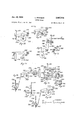
- Fig. 1 is a side elevation of my improved coffee maker, with certain parts in section;
- Fig. 2 is a plan View thereof, with certain parts removed;
- Fig. 3 is a cross-section through a detail of construction
- Fig. 4 is a vertical section along the plane IV--IV of Fig. l;
- Figs. 6, '7, 8 and 9 are various detail views of part of the construction shown in Fig. 5;
- Fig. 10 is a side view of a part of the construction shown in Fig. 5;
- Fig. 11 is a plan view of the showing of Fig. 10;
- Fig. 12 is a broken cross-sectional view along plane XII-XII of Fig. 11;
- Fig. 13 is a horizontal section along plane XIII-XIII of Fig. 1;
- Fig. 14. is a partial sectional view along plane XIV-XIV of Fig. 13;
- Fig. 15 is a partial sectional view along plane XVXV of Fig. 13
- Fig. 16 is a sectional view showing a detail of construction
- Fig. 1'7 is a view partly in diametral section of the dispenser shown in Fig. 1;
- Fig. 18 is a full bottom view of the showing of Fig. 17;
- Fig. 19 is a perspective view of part of the showing of Fig. 17;
- Fig. 20 is a rear view of the timing device according to my invention.
- Fig. 21 is a front view thereof
- Fig. 22 is a right side view thereof
- Fig. 23 is a left side view thereof
- Fig. 24 is a plan view of the timing device of Figs. 20 to 23, showing in addition certain other details of construction;
- Fig. 25 is a vertical section along plane XXVXXV of Fig. 1;
- Figs. 26, 27, 28, 29, 30, 32 and 35 are detail views showing corresponding positions of a number of cam-s which are part of the timing device shown in Figs. 20-24 inclusive;
- Fig. 31 is a top View of part of the showing of Fig.
- Fig. 33 is a left side view of part of the showing of Fig. 32;
- Fig. 34 is a detail view with certain parts removed of part of the showing of Fig. 32.
- Fig. 36 is a wiring diagram for my machine.
- the parts of the machine are assembled on base 1 (Figs. 1, 2, 4 and 5) supported by suitable legs 2.
- Tank 3 is mounted on one end of this base and comprises vertical shell 4 carrying at its upper edge flange 5 to which cover 6 is detachably secured by screws.
- Water enters the tank through pipe In (Figs. 1 and 2) communicating with a water pressure source (not shown in the drawing).
- Flow into the interior of the tank is controlled by needle valve I3 (Figs. 1, 2, 4 and 13) discharging into tube It.
- the operation of valve 13 is controlled by float I6 operating through arm 3 and push rod H5 in such a manner that this valve is closed when the level of water in the tank reaches a predetermined level ind cated by I? (Figs. 1 and 4).
- Water level gauge glass i9 (Fig. 1) communicating at top with the open atmosphere provides convenient means to check this level. Whenever water is withdrawn from the tank, float it; falls slightly, push rod :5 is thereby raised and water flows into the tank from tube i4 via pipe l8 until the predetermined level (M) is reached; Chamber 2
- the amount of gas is controlled by bulb or thermally responsive element 28. located in the lower part of tank 3 directly under the outlet of cold water admission tube I4 and operating through thermostat 21 (Fig. 1) so that whenever cold water is admitted into tank 3 or the water in the bottom of said tank otherwise falls below the boiling point, the burner flame increases.
- the dimensions of identical stacks 23 and 24 are such that enough heat is communicated to the water in the upper part of the tank to keep it at the boiling temperature even though the water in the lower part of the tank is temporarily below the boiling point. This insures that some steam will be continuously generated in the upper part of tank 3, the use and application of which will be described hereinafter.
- thermostat 21 (Fig. 1) cuts down the burner flame.
- the bypass of thermostat 21 is adjusted for minimum flame, such that even when the burner is cut down the necessary extent of boiling and steam evolution in the upper part of tank 3 will be maintained.
- the means described is for the purpose of maintaining a volume of water in tank 3, of maintaining at least the upper part of this water at boiling temperature, and of maintaining controlled evolution of steam therefrom.
- a predetermined amount of water is abstracted from the upper part of tank 3 when the machine is operated.
- the equipment for this purpose includes container 3!] (Figs. 1, 2 and 4) located in the upper r part of tank 3 below water level l7 and vented into the space above said water level ii by pipe 3!.
- Screw 2e secures pipe 31 to shell 4 of tank 3 (Fig. 2).
- Details of the mechanism by which container 35 is alternately filled from tank 3 I or discharged to a point external to said tank appear from Figs. 1, 3 and 4. This comprises pipe 28 extending at one end into container 39 (Figs. 1 and 4) and at the other end into extension 29 of valve 32.
- the plunger 33 of said valve is of the combination slide and poppet type, the side wall fitting snugly bore 34 of valve 32 (Fig. 3), while the frustro-conical surface 35 makes liquid-tight contact with frustro-conical seat 36.
- the plunger is actuated by push rod 3'! operating through stnfling box 38.
- container 36 (Figs. 2 and 4) is in free communication, via pipe 23, with outlet 39 and the contents of container 38 flow out of tank 3.
- outlet 39 is blocked by the poppet valve consisting of surface 35 and seat 36. now in liquid-tight contact, whereupon water flows from the interior of tank 3 through 4 port 40 (Figs. 1 and 3) and through the bore 34 of valve 32 back into container 30.
- the dispenser ii which delivers a predetermined amount of ground roasted cofiee is illustrated in Figs. 1, 2, 17 and 18.
- the dispenser comprises cylindrical bore 42 and integral therewith flange i3 and rim idwhich hold glass cylinder 45.
- the cylinder is surmounted by the removable cover 48.
- the bottom of cylindrical bore 42 is provided with floor 1?.
- Upstanding shaft 48 is journaled in the exact center of this floor. Pinned to this shaft is hub 48 which carries eight radially disposed vanes (Figs. 2 and 17). These vanes define eight pockets (Fig. 2) which by their rotational movement operate to progressively bring charges of cofiee over discharge port 5
- Cover plate 52 (Figs.
- Dispenser 41' additionally requires some means for moving hub 49 and attached vanes 50.
- This means includes gear 59 (Figs. 17 and 18) splined to the lower end of shaft 35. This gear is periodically engaged by a a hook 6i journaled at 62 to arm 63 of bracket 84.
- Spring (Fig. 17) serves to impel said hook into contact with said gear.
- Bracket 65 borne by vertical shaft 65 is bored to loosely engage stub 66 secured in and depending from floor 4'! of the dispenser.
- suitable means is incorporated to hold this charge of coffee in the dispenser unti1 required.
- This means includes plate 13 (Figs. 6 and 7) pivoting about shaft 48 and slidable parallel to discharge port 5
- Hook 72 is journaled at 13 to arm id of horizontal bracket 64,.
- slot 75 of hook 72 engages pin (i on plate 10 and when horizontal bracket 64 and hook 72 actuated thereby move in the reverse direction plate 7!) slides to uncover discharge port 5
- bracket 64 commences to return, shoulder 76 (Fig. 18) of hook 12 is engaged by dog :1 11- iently pivotable about pin 19 against the action of spring 78' one end of which is connected to arm 6] of dog 11 and the other to stub 82 provided on the bottom of floor 41.
- Hook I2 is thereby forced out of engagement with pin H and plate "It returns to closed position, covering port 55, under the influence of spring 83, one end of which is connected topin 84 on arm 85 of plate it while the other end is connected to stud 86 protruding downward from dispenser floor ll.
- the further movement of bracket 54 forces dog l1 out of engagement with shoulder l6, thereby freeing hook I2.
- Plate Ill is supported by rigid bar 8'9 pivotally carried by the lower end of shaft 48.
- the dispenser ll is positioned by bracket 99 (Fig. 1) embracing cylindrical bore @2 of dispenser M, the ends of said bracket 99 being secured to shell 4 of tank 3 (Fig. 1). The dispenser is thus firmly secured in position in themachine.
- this part of the device comprises mixer Hid consisting of cone bottom receptacle IGI surrounded by easing Hi2 and associated means for admixing the cofiee and water.
- Discharge outlet Ei of the dispenser is located di rectly above the mouth of receptacle It! so that the charge of ground roasted cofiee delivered by the dispenser falls directly into said receptacle.
- the predetermined volume of Water abstracted from tank 3 by means hereinabove described is delivered via valve 32 into receptacle it! by spout H13 (Figs. 1, 5, 6 and 13).
- the hot water issues from spout I63 in a well defined stream of considerable velocity through orifice i5 5- (Figs.
- this orifice may be threaded to the spout so that orifices of different capacity may be substituted for one another if it is desired to change the volumetric capacity of the machine.
- this stream from orifice m4 is discharged at a non-central angle intermediate be tween vertical and horizontal and on striking the surface of the liquid already delivered into receptacle Eel it imparts a rotational movement thereto while simultaneously beating down into the liquid any ground coiiee floating on the surface thereof.
- This angle is preferably between 30 and with reference to the horizontal, for maximum eificiency.
- Suitable means is provided for discharging the mixture from receptacle I0! after it has remained in the receptacle a, suitable predetermined period of time.
- This means comprises a valve of special and novel construction (Figs. 5 and 9).
- the mixer discharge outlet I05 is centrally located in the cone bottom hi6 of receptacle IIJI (Fig. 5). This outlet may be closed by the frustro-conical end of poppet-type plug I01.
- plug I01 in turn defines a small outlet Or discharge orifice I08 which may be closed by conical plug N39 secured to the lower end of push rod Ill). These parts are held in alignment by bore III formed in the upper end of plug I07 in which bore push rod H0 recip-rocates.
- the rate of flow from receptacle IIlI is a function of the total heighth of liquid in said receptacle and said rundown tube In and is therefore only limitedly affected by the drop in level in receptacle It!
- an orifice is provided in the lower end of the outlet tube. Being so mounted the orifice will at all times be operating under a full head of liquid and the rate of fiow will therefore be controlled. by the size of the orifice and by the head.
- the size of the orifice can be varied until the desired rate of flow out of the mixing receptacle is obtained. In this way it is possible to establish approximately the correct diameter of orifice, and the size of orifice having been so established the orifice is now moved from the lower end of the outlet tube to the upper end of the outlet tube. Two procedures are now available for determining the correct size of the outlet tube to be operated in conjunction with the size of the orifice so established.
- an outlet tube of transparent material such as glass may be temporarily provided and tubes of varying diameter are substituted until with increasing diameter it is found that the tube will not carry a solid column of liquid but that the column will break and will at least partly acct 14 let tube tobe adopted in practice should approach themaximum diameter at which a" solid column of liquid is obtained under these conditions thereby insuring a uniform discharge of the mixture from the mixing receptacle into the centrifuge coupled with the maximum rate of discharge of the flush water hereinafter refer-red to.
- an outlet tube of metal may be used and tubes of varying diameter substituted until a diameter is reached at which the outflow from the mixing receptacle through the orifice is not uniform and sustained but pro contra falls off sharply with the reduction of liquid level in the mixing receptacle.
- the tube to be adopted and installed should approach the maximum diameter at which the rate of outflow from the mixing receptacle is a function of the total head within the mixing receptacle and the outlet tube and is therefore relatively unaffected by a reduction in liquid level within the mixing receptacle.
- squirts of water are tangentially introduced (Figs. 5 and 13) by nozzles IIB. These nozzles are bored in small turrets II9 spun into the inner surface of the side wall of receptacle IiiI. A detail view of one such nozzle is shown in Fig. 8.
- Flush water is carried to said nozzles by annular ring I20 set in the top of mixer Iiifl (Fig. 5) and the flush water is carried into ring I29 by tube I2I (Figs. 1 and 5). The means for the supply of flush water to tube I2! is described hereinbelo'w.
- the centrifuge I23 (Fig. 5) preferably of chromium steel or stainless steel, comprises upper tubular section i2 5 which terminates in inwardly projecting overflow lip I25 and lower tubular section E26 of a diameter greater than section I22.
- the lower end I26 of centrifuge 523 is spanned by the annular closure I2! carrying the centrally located discharge tube I28.
- the centrifuge is started in rotation so that it comes to full speed before plug I69 lifts and orifice I 68 is uncovered. Thereafter the mixture of grounds and extract runs at a uniform rate through mixer outlet I05 to tube II! and is diverted horizontally from the lower end of tube I IT by spinning saucer I30.
- Figs. l0, l1 and 12 for details of this saucer, it can be noted that the circumference of this saucer is provided with a series of vertical teeth I37. These teeth act as an impeller ring to increase the velocity with which the mixture of ground coffee and water issuing from outlet tube II! is thrown horizontally into lower tubular portion I26 of centrifuge 523. In order to prevent coffee grounds from being retained in said saucer by the inner surfaces of said teeth, said surfaces are inclined downwards, preferably forming a continuation of the radial bevel of said saucer, and may in. addition also be provided with lateral bevels as shown in the drawing (Figs. 11- and 12). Saucer I36 is carried by two posts I3I (Fig.
- baffles I35 provided in upper tubular section I24 of the centrifuge (Fig. 5).
- FIG. 7 for a detail view of one of these baffles it is noted that they are peripherally cut away to form concentric slots I35 through which the mixture passes adjacent the inner wall of upper centrifuge section I24, and are provided with central opening I37 to clear rundown tube II! (Fig. 5), but are otherwise imperforate so that material cannot flow telescopically up the centrifuge.
- the baffles are secured in position in any suitable manner.
- This collector ring is provided with boss I42 by which it is secured to cylindrical casing I43.
- boss I42 By reference to the partial view of collector ring I4I contained in Fig. 15, it will be noted that the beverage discharges from said collector ring through boss i42 into accumulator I44 by means of spout I45. This spout debauches into thimble I46, forming a hydrostatic seal, the function of which will be hereinafter considered.
- Accumulator H44 (Figs. 1, 2, 13, 14 and 15) comprises spaced concentric glass cylinders I4! and I48 (Fig. 14) closed by top and bottom end plates I43 and I50, respectively, held together by rods II.
- Faucet I52 (Figs. 1, 2 and 15) is provided for drawing off the coffee beverage.
- Bracket I53 (Fig. 14) extends downwards from end plate I49 to support thimble I45.
- Cover plate I54 (Fig. 13) slidable parallel to top end plate I49 provides access to the accumulator for cleaning purposes.
- Float I55 vertically displaceable in housing I56 (Fig. 14) is responsive to the liquid level within said accumulator. This float is provided with vertical guide pin I51, rigidly attached thereto.
- Centrifuge I23 is journaled in bearing I59 (Fig. 5).
- This bearing defines annular space I10, closed by annular ring m3, into which space oil for lubrication is introduced through oil hole I'II connecting with force-feed lubrication line I12. The oil moves to the bearing surface through hole 873. Any oil thrown off from the upper surface of bearing I59 is deflected by apron I14 into annular trough I'I5, from which it discharges through port I'IIS onto shelf I'I'I secured to the side wall of the centrifuge and serving to deflect the oil into annular trough 513.
- centrifuge I23 is abruptly stopped by means of brake 331 (Fig. 1) to be hereinafter described.
- brake 331 Fig. 1
- the residue of grounds and water remaining in the centrifuge continues to rotate for a few seconds until its momentum has become dissipated.
- This scours and cleans the inner surface of centrifuge I23 and as soon as the momentum has been dissipated in this manher the mixture flows out of the centrifuge through discharge tube I23 and out of the apparatus through waste pipe I33.
- jets of hot water are discharged against the inner walls of receptacle IN and of centrifuge I23 thereby completing the cleaning operation.
- the means for the accomplishment of this cleaning operation comprises coil I93 surrounding flue 2i in tank 3 (Figs. 1, 4 and 13) and branching off from water inlet pipe I8 below needle valve I3.
- the other end of coil I95 communicates via flush control valve I9I (Figs. 1,
- Pipe I53 communicates in turn with conduit I34 (Fig. 5) within casing 532 of mixer I35, which conduit terminates in chamber I9? concentrically arranged about mixer discharge outlet I35 and delivery tube II'I.
- Flush tube I35 extends downwards from chamber I91, so as to provide an annular space concentrically surrounding rundown tube Hi. This annular space is sealed ofi slightly above teeth I32 of saucer I35, and flush tube IE5 is provided with a multiplicity of orifices I33 forming outlets for the flush water.
- Tube I2I providing flush water via nozzles II8 to receptacle. IfiI, as described above, branches off from pipe I93. This tube is provided with U-bend i523 Y to provide a hydrostatic seal in said tube.
- flush control valve ISI (Figs. 1, 4 and 13) is actuated by means hereinafter to be described, water which has been heated incoil I93 to C. and which is under the full pressure of the main water supply, for instance the municipal water system, discharges through orifices E38 and nozzles II 8 (Fig. 5) thereby flushing out receptacle IllI aand centrifuge I23 respectively.
- burner 22 (Figs. 1 and 4) heating the water in tank 3 is so controlled, thermostatically, that some boiling is always taking place in the upper part of tank 3' with consequent generation and evolution of steam.
- This steam passes downwardly through vertical pipe ZDI (Figs. 1, 2 and 13) and thence via hori zontal pipe 232 into casing I32 (Figs. 2, 5 and 13).
- Some of the steam condenses to maintain receptacle IllI, centrifuge I23, collector ring MI and associated parts (Fig. 5) at 100 C. thereby insuring efficient operation regardless of the standby periods and also sterilizing centrifuge I23 and collector ring 541.
- the timer 220 (Figs. 1 and -24) comprises pulley 22I driving ,through three reduction gears (not shown in the drawing) contained in reduction gear housing 222, worm 223 which in turn drives gear 224 splined onto jackshaft 225.
- Pulley -22I is driven by V-belt 225 from motor 227 (Fig. 1).
- jackshaft 223 carries seven cams by which the said temporal sequence is determined which cams will be hereinafter more particularly described.
- Said jackshaft 226 is journaled in holes bored in the uprights 228 and 229, which in turn are suspended from the underside of base I (Fig. 1). These uprights are mounted on reservoir cover plate 352, and are further laterally support ed by cross-plates 2I6 and 2H.
- Motor 227 is carried laterally by cross-member 230 secured to legs 2 (Fig. 1).
- Cam rider shaft 23I is likewise journaled in holes bored in uprights 228 and 229.
- Shaft 232 is secured in brackets 23! supported on vertical panel 233, this shaft serving as pivot for mercury switches 234 and 235 the purpose of which is hereinafter explained.
- Panel 233 is cut out to permit the pivoting of these switches.
- Trough 236 is supported by staybolts 2I8 and 2l9 secured between uprights 228 and 223. to retain a bath of oil or grease into which the cams dip and which, therefore, provides them with adequate lubrication.
- Jackshaft 226 is so geared to timer motor 22'! that it and the cams carried thereby make a com plete revolution in one cycle of the apparatus.
- the construction of the cams will be-described by reference to one specific embodiment of the apparatus which has a cycle time of 90 seconds.
- centrifuge I23 (Fig. 5) has an overall inside length of thirteen inches.
- the inside diameter of the base portion I is three inches, inside height of this portion two and three-sixteenths inches, inside diameter of upper portion I24 of the centrifuge'one andonehalf inches, inside diameter of the overflow lip I25 one inch.
- Rundown tube II! is of inch bore and orifice I08 of plug I01 is of 1% inch bore. This centrifuge is operated successfully at about 5000 R.
- the centrifuge may, of course, be operated at higher or lower speeds, if desired, and the output per-cycle maybe increased or decreased, depending upon the strength desired.
- the cycle time and cycleoutput de- This trough (Figs. 1 and 20-24) functions scribed, the amount of codes introduced may be in the proportion of one pound of coffee to about 35 cups of finished beverage or about one pound of coffee to about 45 cups of finished beverage, or in any intermediate proportion.
- cam 249 (Figs. 20-24).
- a detail view of this cam is shown in Fig. 26.
- This cam carried by jackshaft 226 controls the operation of the mixer "outlet valve I05 shown in Figs. 5 and 9.
- projection 250 of rider 25I carried by shaft 23I climbs to the surface 252 of cam 249, thereby lifting push rod 253.
- This .push rod is connected via link 254 (Fig. 1) pivoted on bracket 255 secured to base I, with rod 248.
- Arm 256 extends horizontally from rod 248, its outer :end being displaceable between collars 251 and 258 on push rod H0 (Fig. 1).
- FIG. 29 A detail view of this cam is shown in Fig. 29.
- This cam controls the operation of the mixer water inlet valve 32 shown in Fig. 1.
- projection 266 Fig. 29
- Projection 255 continues to ride on surface 268 until 20 seconds after the time of initial contact, whereupon projection 26% is returned to surface 2% by the pull exerted by spring 264.
- projection 288 was in the elevated position, push rod Eli was lifted, thereby lifting connected yoke 212 (Fig. 1) and opening valve 32 (Fig. 13).
- orifice Hl i (Fig. is so chosen that approximately five cups of Water pass into receptacle IIlI during the period that valve 32 is so opened.
- valve 32 is closed by the return of push rod 21! and remains closed until 57 seconds after initial contact when projection 226 runs up onto surface 2'13 (Fig. 29) of cam 255. It continues to ride on this surface 213 until 67 seconds after the time of initial contact, whereupon projection 2'66 runs down onto surface 2M and valve 32 is again closed. From 2.5 to 3 cups of water will have entered receptacle IOI during this period.
- Cam 30f! (Figs. 20-24), next to be considered, controls the operation of centrifuge motor 292.
- This motor operating through pulley 293 drives pulley I49 (Figs. 1 and 5) of centrifuge I23 via V-belt 138.
- motor 292 is secured to leg 2 of base I (Fig. 1).
- jackshaft 226 carries cam 392.
- Cam rider 3!! pivotally mounted on rod 23! has projection 302 which rides on the surface of this cam. Rider 3!!! is connected through link 302 to rocker 3B5 pivotally carried by shaft 232.
- Rocker 305 carries mercury switch 235.
- link 304 changes the angle of rocker 1365, thereby throwing mercury switch 235 carried thereby to the oil-position.
- this switch is in series with and controls centrifuge motor 292.
- link 3M To bell arm 396 (Fig. 28) of rider 363! there is pivoted link 3M, the other end of which is pivoted about pin 3!) provided in yoke 3I5 of brake drum 3%)? (Figs. 24 and 28).
- link SM is retracted, thereby pulling brake drum 31)! and brake surface 328 away from engagement with the outside of lower section I22 of centrifuge I23 (Fig. 1).
- Figs. 1 As shown in Figs.
- brake drum 381 is slidably carried by rods 309 and 3H] mounted in uprights 228 and 222.
- Springs 3! and 3I2 urge brake drum 38! toward lower section I26 of centrifuge I23 and as soon as projection 3M rides off of the elevated surface 323 these springs apply the brake and arrest the rotation of the centrifuge; simultaneously spring 323 connected between rocker 355 and panel 233 returns mercury switch 235 to the ofi-position, thereby killing centrifuge motor 292.
- Cam 336i mounted on shaft 226 defines a discontinued surface of progressively increasing radius. As the cam revolves, during the machine cycle, it progressively forces upward lever 33! pivotally connected to spacer 328 on the side of uprigt 229 (Figs. 21, 23 and 32) by pin 332. This upward movement compresses coil spring 333 positioned by retainers 346 and 34'! against lever see which is also pivotally connected to said spacer328 by pin 335. Attention secure is called to thefact that thepivot points of levers 33f and 33 3 do not lie in the same vertical plane (Fig. 32).
- Lever 33 i cannotmove upwardly because it is restrained by trigger 333 pivotally' connected to spacer 32-3 onthe side of upright 229 (Figs. 20 and 21 by pin 33 1 At'the: exact moment at which it isdesired to'actuate' the flush valve, trigger 33B is forced ofl'of the-end of lever 334- by pin 338', thereby releasing lever 33 i and actuating push rod 326.
- the angular divergence between levers 334 and 33f is, however, limited by roller 339 rotatably supported by pin 346 in oversize bore 351'.
- Leaf spring 342' tendsto hold roller 33% the position shown in'Eig. 341 Housing 3 53 car iedby lever 33 i supports pin- 3M?
- cam rider 350- pivotall'y carried by shaft 23f has projection 35f which rides on the surface of cam 352, mounted onshaft' 226.
- the rotational movement of am 352'- operating through linl: 353 alternately-ra-ises-oil pump piston 354.
- the reverse movement" of piston 35-2 is effected by spring 356-.
- Oil reservoir cover plate 352 is supported from base i by uprights 225' and 229 (Figs. -24) and reservoir 35'! is suitably secured to the bottom of said cover plate.
- the reservoir may be periodically replenished through fill pipe 363.
- the reservoir is provided with a riser 355 which is connected by duct 365 with the main body of reservoir 35-1. Ifwater finds its way into the oil reservoir, as, for example, the result of leakage, carelessness in cleaning, or possibly leakage of steam into the main bearings, the water accumulates in the lower part of reservoir 353' and the oil is thereby lifted into risers 363 and Bit until the compound head of thewater and of the oil resting thereon counterbalances the hydrostatic head of a column of water in riser 365 extending up to outlet 364.
- Piston 35 i reciprocates in liner 369 provided in pump block (ill, said liner extending upwards through riser 353 (Fig. 25).
- cams illustrated are of suitable outline for a coffee maker operating on an overall 90 second cycle with a production of 5 cups of finished beverage per cycle. The following. arethe approximate times maintained by a timer found entirely satisfactory.-
- Mixer inlet valve 32 closes: Determined by projcclion 266 riding downoff elevated surface 7 268 onto surface 2(59'of cam 265 (Fig. 29).
- Mixer outlet orifice 108 opens: Determined by projcction 250 running off of-clcvotcd surface 252 onto surface 259 of com 242 (Fig. 26).
- Mixer discharge outlet 105 opens: Determined by projection 250 running off of surface 259 onto surface 261 of com 249 (Fig. 26).
- Flush valve 191 opens: Determined by pin 388 of cam 330 releasing lever 334 from engagement with'triggcr 336 (Fig. 32).
- a coffee maker including a centrifuge of the imperforate overflow self-dumping type, a cone bottom receptacle adapted to hold a mixture of ground roasted coffee and hot water, a rundown: tube extending from the center of said Determined by projection 362-running up on Mixer inlet valve 32 opens: Determined by 'Mixcr inlet valve 32 closesz'Dcf'crmined by l7 cone bottom into the lower end of said centrifuge, a valve adjacent the center of saicl cone bottom controlling flow out of said receptacle through said tube a enser surmounting said re ceptacie adap d to deliver a predetermined of [Z roasted coffee, a non-pressure tank, water contained in said tank, an chi-3e c charging downwardly into said receptacle, sucplying hot Water from said to orifice, a timer ted in suc-- cessicn to (a) close said valve; (b) start flow
- said orifice being so oriented that the vertical plane which bisects the same is non-central with respect to said receptacle and. tangent to a cylinder of lesser radius than said receptacle whereby the stream from said orifice imparts a rotational movement to liquid in said .”llile simultaneously beating into said liquid ny ground coffee floating on the surface thereof.
Landscapes
- Engineering & Computer Science (AREA)
- Food Science & Technology (AREA)
- Apparatus For Making Beverages (AREA)
Description
L. BURGESS COFFEE MAKER Jan. 26, I954 10 Sheets-Sheet 2 Original Filed July 12, 1947 INVENTOR Wm L. BURG ESS COFFEE MAKER Jan. 26, 1954 10 Sheets-Sheet 3 Original Filed July 12, 1947 L. BURGESS COFFEE MAKER Jan. 26, 1954 l0 Sheets-Sheet 4 Original Filed July 12, 1947 an W.-
Jan. 26, 1954 10 Sheets-Sheet 5 Original Filed July 12, 1947 INVENTDR Jan. 26, 1954 L. BURGESS COFFEE MAKER 10 Sheets-Sheet 6 Original Filed July 12, 1947 Jan. 26, 1954 BURGESS 2,667,114
COFFEE MAKER Original Filed July 12. 1947 10 Sheets-Sheet 7 352 um L 219 Z] INVENTOR Jan. 26; 1954 BURGESS 2,667,114
COFFEE MAKER Original Filed July 12, 1947 10 Sheets-Shet 8 INVENTOR Jan. 26, 1954 BURGESS 2,667,114
COFFEE MAKER Original Filed July 12, 1947 10 Sheets-Sheet 9 .362 ,mm a
INVENTOR L. BURGESS COFFEE MAKER Jan. 26, 1954 10 Sheets-Sheet 10 Original Filed July 12, 1947 INVENTOR Patented Jan. 26, 1954 COFFEE MAKER Louis Burgess, Jersey City, N. J.
Original application July 12, 1947, Serial No. 760,599. Divided and this application October 28, 1949, Serial No. 124,065
1 Claim.
The present invention is an improvement upon the coiiee maker described in my U. S. Patent 2,149,270 of March 7, 1939, and is a division of my copending application, Serial No. 760,599 filed July 12, 1947, now Patent Number 2,589,221.
The machine shown and described in my said prior patent in the complete form in which it is adapted for restaurant and similar use includes the following:
A. A tank from which a predetermined amount of hot water is extracted whenever the machine is operated. The water in this tank is automatically maintained at a predetermined level by a float control inlet valve and this water is automatically maintained at boiling temperature by a thermostatically controlled heating device.
B. A dispenser which delivers a predetermined amount of ground roasted coffee when the machine is operated.
C. A receptacle into which said coffee and said water are introduced and in which they are mixed.
D. An imperforate self-dumping overflow type centrifuge into which the mixture of coffee and water flows from said receptacle and in which the mixture is separated into a clarified coffee beverage which overflows the upper lip or rim of the centrifuge and a residue of coiiee grounds which is ejected from said centrifuge after said centrifuge has stopped.
A collector ring encircling the overflow lip or rim of the centrifuge by which the clarified coiiee beverage is collected and from which it is conducted to a suitable receptacle.
F. An automatic timing device whereby the steps involved in the operation of the machine are carried through in sequence whenever the machine is set in operation.
The improvements to this machine constituting the present invention will be fully understood from the following description read in conjunctien with the drawing in which:
Fig. 1 is a side elevation of my improved coffee maker, with certain parts in section;
Fig. 2 is a plan View thereof, with certain parts removed;
Fig. 3 is a cross-section through a detail of construction;
Fig. 4 is a vertical section along the plane IV--IV of Fig. l;
5 a vertical section along plane V--V ".1" 1- lg. 1;
Figs. 6, '7, 8 and 9 are various detail views of part of the construction shown in Fig. 5;
Fig. 10 is a side view of a part of the construction shown in Fig. 5;
Fig. 11 is a plan view of the showing of Fig. 10;
Fig. 12 is a broken cross-sectional view along plane XII-XII of Fig. 11;
Fig. 13 is a horizontal section along plane XIII-XIII of Fig. 1;
Fig. 14. is a partial sectional view along plane XIV-XIV of Fig. 13;
Fig. 15 is a partial sectional view along plane XVXV of Fig. 13
Fig. 16 is a sectional view showing a detail of construction;
Fig. 1'7 is a view partly in diametral section of the dispenser shown in Fig. 1;
Fig. 18 is a full bottom view of the showing of Fig. 17;
Fig. 19 is a perspective view of part of the showing of Fig. 17;
Fig. 20 is a rear view of the timing device according to my invention;
Fig. 21 is a front view thereof;
Fig. 22 is a right side view thereof;
Fig. 23 is a left side view thereof;
Fig. 24 is a plan view of the timing device of Figs. 20 to 23, showing in addition certain other details of construction;
Fig. 25 is a vertical section along plane XXVXXV of Fig. 1;
Figs. 26, 27, 28, 29, 30, 32 and 35 are detail views showing corresponding positions of a number of cam-s which are part of the timing device shown in Figs. 20-24 inclusive;
Fig. 31 is a top View of part of the showing of Fig.
Fig. 33 is a left side view of part of the showing of Fig. 32;
Fig. 34 is a detail view with certain parts removed of part of the showing of Fig. 32.
Fig. 36 is a wiring diagram for my machine.
The parts of the machine are assembled on base 1 (Figs. 1, 2, 4 and 5) supported by suitable legs 2. Tank 3 is mounted on one end of this base and comprises vertical shell 4 carrying at its upper edge flange 5 to which cover 6 is detachably secured by screws. Water enters the tank through pipe In (Figs. 1 and 2) communicating with a water pressure source (not shown in the drawing). Flow into the interior of the tank is controlled by needle valve I3 (Figs. 1, 2, 4 and 13) discharging into tube It. The operation of valve 13 is controlled by float I6 operating through arm 3 and push rod H5 in such a manner that this valve is closed when the level of water in the tank reaches a predetermined level ind cated by I? (Figs. 1 and 4). Water level gauge glass i9 (Fig. 1) communicating at top with the open atmosphere provides convenient means to check this level. Whenever water is withdrawn from the tank, float it; falls slightly, push rod :5 is thereby raised and water flows into the tank from tube i4 via pipe l8 until the predetermined level (M) is reached; Chamber 2| is oren at the bottom to receive heat from burner 22 (Figs. 1 and 4) and at its top communicates with identical stacks 23 and 24 (Figs; 1, 2, 4 and 13). The function of chamber 21 is to transfer the heat delivered by burner 22 to the water in the tank, while stacks 23 and 2'4- carry off the gaseous combustion productsof the burner. Burner 22 receives; gas through pipe 25' (Fig. 1). The amount of gas is controlled by bulb or thermally responsive element 28. located in the lower part of tank 3 directly under the outlet of cold water admission tube I4 and operating through thermostat 21 (Fig. 1) so that whenever cold water is admitted into tank 3 or the water in the bottom of said tank otherwise falls below the boiling point, the burner flame increases. The dimensions of identical stacks 23 and 24 are such that enough heat is communicated to the water in the upper part of the tank to keep it at the boiling temperature even though the water in the lower part of the tank is temporarily below the boiling point. This insures that some steam will be continuously generated in the upper part of tank 3, the use and application of which will be described hereinafter. When the water in the lower part of tank 3 is at the boiling point thermostat 21 (Fig. 1) cuts down the burner flame. The bypass of thermostat 21 is adjusted for minimum flame, such that even when the burner is cut down the necessary extent of boiling and steam evolution in the upper part of tank 3 will be maintained.
Up to this point the means described is for the purpose of maintaining a volume of water in tank 3, of maintaining at least the upper part of this water at boiling temperature, and of maintaining controlled evolution of steam therefrom.
In the operation of the machine, a predetermined amount of water is abstracted from the upper part of tank 3 when the machine is operated. The equipment for this purpose includes container 3!] (Figs. 1, 2 and 4) located in the upper r part of tank 3 below water level l7 and vented into the space above said water level ii by pipe 3!. Screw 2e secures pipe 31 to shell 4 of tank 3 (Fig. 2). Details of the mechanism by which container 35 is alternately filled from tank 3 I or discharged to a point external to said tank appear from Figs. 1, 3 and 4. This comprises pipe 28 extending at one end into container 39 (Figs. 1 and 4) and at the other end into extension 29 of valve 32. The plunger 33 of said valve is of the combination slide and poppet type, the side wall fitting snugly bore 34 of valve 32 (Fig. 3), while the frustro-conical surface 35 makes liquid-tight contact with frustro-conical seat 36. The plunger is actuated by push rod 3'! operating through stnfling box 38. When the plunger is in the position shown in Fig. 3, container 36 (Figs. 2 and 4) is in free communication, via pipe 23, with outlet 39 and the contents of container 38 flow out of tank 3. When, however, plunger 33 is in its lowest position, outlet 39 is blocked by the poppet valve consisting of surface 35 and seat 36. now in liquid-tight contact, whereupon water flows from the interior of tank 3 through 4 port 40 (Figs. 1 and 3) and through the bore 34 of valve 32 back into container 30.
The dispenser ii which delivers a predetermined amount of ground roasted cofiee is illustrated in Figs. 1, 2, 17 and 18. The dispenser comprises cylindrical bore 42 and integral therewith flange i3 and rim idwhich hold glass cylinder 45. The cylinder is surmounted by the removable cover 48. The bottom of cylindrical bore 42 is provided with floor 1?. Upstanding shaft 48 is journaled in the exact center of this floor. Pinned to this shaft is hub 48 which carries eight radially disposed vanes (Figs. 2 and 17). These vanes define eight pockets (Fig. 2) which by their rotational movement operate to progressively bring charges of cofiee over discharge port 5|: in floor 4? (Fig. 18). Cover plate 52 (Figs. 2 and 17) secured to cylindrical bore 42 (Fig; 17) overlays port 5! to prevent coffee from running out of said port (Fig. 18) except as transported by vanes 53 to a position overlaying said port. To the upper part of shaft 48 there is pinned hub '55 (Figs. 2 and 1'?) bearing three sweeps 56 which sweep the upper surface of cover plate 52 to prevent accumulation of ground coffee thereon.
Dispenser 41' additionally requires some means for moving hub 49 and attached vanes 50. This means includes gear 59 (Figs. 17 and 18) splined to the lower end of shaft 35. This gear is periodically engaged by a a hook 6i journaled at 62 to arm 63 of bracket 84. Spring (Fig. 17) serves to impel said hook into contact with said gear. Bracket 65 borne by vertical shaft 65 is bored to loosely engage stub 66 secured in and depending from floor 4'! of the dispenser. As is evident from this construction, when shaft 65 and bracket 64 carried thereby are moved in one direction, hub 49 will be carried through a fraction of a complete revolution, but when shaft 65 and therewith bracket 64 move in the reverse direction, hook 6| will merely slide over the beveled teeth of gear 59 (Fig. 18) without moving hub 49 (Fig. 17). In practice, I find it highly advisable that this movement be carried out gradually and progressively throughout the major-part of the operating cycle of the machine. This being the case, it is evident that unless suitable provision were made, the coffee in the pocket, formed by two of vanes 50, moving over discharge port 5| (Figs. 2, 17 and 18) would fall continuously out through said discharge port. Inasmuch as the coffee must however be discharged at the commencement of the operating cycle, suitable means is incorporated to hold this charge of coffee in the dispenser unti1 required. This means includes plate 13 (Figs. 6 and 7) pivoting about shaft 48 and slidable parallel to discharge port 5| to uncover same. Hook 72 is journaled at 13 to arm id of horizontal bracket 64,. When hook 6! reaches the position of maximum advance, the pocket defined by two of vanes 50 has been brought directly over discharge port 5|. At this time slot 75 of hook 72 engages pin (i on plate 10 and when horizontal bracket 64 and hook 72 actuated thereby move in the reverse direction plate 7!) slides to uncover discharge port 5|. This uncovering is effected at a suitable time in the beginning of the machines cycle as will be hereinafter explained. When bracket 64 commences to return, shoulder 76 (Fig. 18) of hook 12 is engaged by dog :1 11- iently pivotable about pin 19 against the action of spring 78' one end of which is connected to arm 6] of dog 11 and the other to stub 82 provided on the bottom of floor 41. Hook I2 is thereby forced out of engagement with pin H and plate "It returns to closed position, covering port 55, under the influence of spring 83, one end of which is connected topin 84 on arm 85 of plate it while the other end is connected to stud 86 protruding downward from dispenser floor ll. The further movement of bracket 54 forces dog l1 out of engagement with shoulder l6, thereby freeing hook I2. Plate Ill is supported by rigid bar 8'9 pivotally carried by the lower end of shaft 48.
Some of the finer grades of coffee manifest a tendency to stick together and may for this reason not be completely discharged from the space overlaying port 5| even though plate H3 has uncovered said port. This dimculty is, how ever, overcome by upwardly projecting teeth 90 and 9| (Fig. 17) carried by plate I0, which teeth project up into the space traversed by vanes 59 and rip and dislodge the coffee above discharge port 5! so that it is fully discharged. A perspective view of one such tooth is shown in Fig. 19. As is evident from Fig. 6, vanes define slots or cut-out portions 92 which enable vanes 59 to clear teeth 9t, 9! in their progressive rotational movement.
The dispenser ll is positioned by bracket 99 (Fig. 1) embracing cylindrical bore @2 of dispenser M, the ends of said bracket 99 being secured to shell 4 of tank 3 (Fig. 1). The dispenser is thus firmly secured in position in themachine.
That part of the machine by which the predetermined volume of coffee delivered by disthese figures, this part of the device comprises mixer Hid consisting of cone bottom receptacle IGI surrounded by easing Hi2 and associated means for admixing the cofiee and water. Discharge outlet Ei of the dispenser is located di rectly above the mouth of receptacle It! so that the charge of ground roasted cofiee delivered by the dispenser falls directly into said receptacle. The predetermined volume of Water abstracted from tank 3 by means hereinabove described is delivered via valve 32 into receptacle it! by spout H13 (Figs. 1, 5, 6 and 13). The hot water issues from spout I63 in a well defined stream of considerable velocity through orifice i5 5- (Figs. 5 and 6). This orifice may be threaded to the spout so that orifices of different capacity may be substituted for one another if it is desired to change the volumetric capacity of the machine. As indicated in the drawing (Figs. 5, 6 and 13) this stream from orifice m4 is discharged at a non-central angle intermediate be tween vertical and horizontal and on striking the surface of the liquid already delivered into receptacle Eel it imparts a rotational movement thereto while simultaneously beating down into the liquid any ground coiiee floating on the surface thereof. This angle is preferably between 30 and with reference to the horizontal, for maximum eificiency. As a result the cofiee and water introduced into receptacle iii! are thorough-1y and eificiently commingled by the velocity of the water introduced and without r sort to a mechanical mixing device.
Suitable means is provided for discharging the mixture from receptacle I0! after it has remained in the receptacle a, suitable predetermined period of time. This means comprises a valve of special and novel construction (Figs. 5 and 9). The mixer discharge outlet I05 is centrally located in the cone bottom hi6 of receptacle IIJI (Fig. 5). This outlet may be closed by the frustro-conical end of poppet-type plug I01. Referring to Figure 9, it can be noted that plug I01 in turn defines a small outlet Or discharge orifice I08 which may be closed by conical plug N39 secured to the lower end of push rod Ill). These parts are held in alignment by bore III formed in the upper end of plug I07 in which bore push rod H0 recip-rocates. The central portion of said plug I0! is cut away leaving only two posts II 4, thus permitting free access of the mixture of water and coffee to orifice I68. When the valve is in the position illustrated in Fig. 5, i. e., with push rod H0 in depressed condition, discharge outlet I05 is blocked by plug I67 and orifice m8 is blocked by plug I99. In this position the mixture of cofiee and water is of course held in receptacle IDI. At the expiration of a predetermined period of time a controlled and uniform stream of the mixture is supplied to the centrifugal separator to be hereinafter more fully described. For this purpose. the pressure on push rod I I0 is released whereupon spring l I5 pressing against collar II6 pinned to rod llii forces upwardly said rod and plug we carried thereby, thereby uncovering orifice I68. This position of the valve is shown in Fig. 9. The diameter of this orifice and of the rundown tube Ill (Fig. 5) are interrelated. If the rundown tube is too small the requisite rate of fiow cannot of course be maintained and conversely if it be too large it will not carry a solid column of liquid, whereupon suction on orifice I88 will be lost and the rate of How out of receptacle III! will fall off rap-idly with diminishing level of the material in receptacle Itl. Within these limits the rate of flow from receptacle IIlI is a function of the total heighth of liquid in said receptacle and said rundown tube In and is therefore only limitedly affected by the drop in level in receptacle It! For the purpose of establishing the diameter of the orifice and of the outlet tube the following procedure is recommended. Having established the dimensions of the mixing receptacle and the length of outlet tube required to carry the mixture from the receptacle into the base of the centrifuge, an orifice is provided in the lower end of the outlet tube. Being so mounted the orifice will at all times be operating under a full head of liquid and the rate of fiow will therefore be controlled. by the size of the orifice and by the head. Under these conditions, the size of the orifice can be varied until the desired rate of flow out of the mixing receptacle is obtained. In this way it is possible to establish approximately the correct diameter of orifice, and the size of orifice having been so established the orifice is now moved from the lower end of the outlet tube to the upper end of the outlet tube. Two procedures are now available for determining the correct size of the outlet tube to be operated in conjunction with the size of the orifice so established. In one procedure an outlet tube of transparent material such as glass may be temporarily provided and tubes of varying diameter are substituted until with increasing diameter it is found that the tube will not carry a solid column of liquid but that the column will break and will at least partly acct 14 let tube tobe adopted in practice should approach themaximum diameter at which a" solid column of liquid is obtained under these conditions thereby insuring a uniform discharge of the mixture from the mixing receptacle into the centrifuge coupled with the maximum rate of discharge of the flush water hereinafter refer-red to. In the alternate procedure an outlet tube of metal may be used and tubes of varying diameter substituted until a diameter is reached at which the outflow from the mixing receptacle through the orifice is not uniform and sustained but pro contra falls off sharply with the reduction of liquid level in the mixing receptacle. Based on these observations the tube to be adopted and installed should approach the maximum diameter at which the rate of outflow from the mixing receptacle is a function of the total head within the mixing receptacle and the outlet tube and is therefore relatively unaffected by a reduction in liquid level within the mixing receptacle.
At the complete end of the operating cycle it has been found necessary to flush out receptacle IGI and at this time and for this purpose squirts of water are tangentially introduced (Figs. 5 and 13) by nozzles IIB. These nozzles are bored in small turrets II9 spun into the inner surface of the side wall of receptacle IiiI. A detail view of one such nozzle is shown in Fig. 8. Flush water is carried to said nozzles by annular ring I20 set in the top of mixer Iiifl (Fig. 5) and the flush water is carried into ring I29 by tube I2I (Figs. 1 and 5). The means for the supply of flush water to tube I2! is described hereinbelo'w. During this stage of the operating cycle free discharge from receptacle IEII is desirable and this is accomplished by further lifting push rod I I so that plug I0? is unseated and the liquid passes out of receptacle IEJI through the full opening of discharge outlet I55 (Fig.5).
Inasmuch as tramp material occasionally finds its way into the dispenser and. since such tramp material might plug orifice I33 and thereby disturb the working of the machine, said orifice is surrounded by frustro-conical screen I22 (Fig. 5). This screen is of perforated metal, the perforations being approximately inch indiameter on inch centers. t operates to prevent tramp material finding its way to orifice I08 and also functions as a guide surface for plug N11.
The construction of the centrifugal separator and ancillary parts is shown in Figs. 5, 7, 10, 11 and 12. The centrifuge I23 (Fig. 5) preferably of chromium steel or stainless steel, comprises upper tubular section i2 5 which terminates in inwardly projecting overflow lip I25 and lower tubular section E26 of a diameter greater than section I22. The lower end I26 of centrifuge 523 is spanned by the annular closure I2! carrying the centrally located discharge tube I28. It has been found in practice that the larger particles in the coffee grind are quick- 1y thrown out in the of the centrifuge and tend to accumulate at this point, but that if the centrifuge is made uniformly large enough in diameter to accommodate this accumulation, the peripheral velocity of discharge from the overflow lip is so great as to introduce cloud into the beverage. By the special form of centrifuge shown in Fig. 5, the accumulation in the base of the centrifuge is provided for and any tendency to plug as the result of the use of too coarse a grind is obviated, while the upper tubular section I24 of the centrifuge is freed of the load of the coarser particles and a higher clarification eificiency is maintained with minimum peripheral velocity of discharge and minimum cloud. In practice, the centrifuge is started in rotation so that it comes to full speed before plug I69 lifts and orifice I 68 is uncovered. Thereafter the mixture of grounds and extract runs at a uniform rate through mixer outlet I05 to tube II! and is diverted horizontally from the lower end of tube I IT by spinning saucer I30.
Referring to Figs. l0, l1 and 12 for details of this saucer, it can be noted that the circumference of this saucer is provided with a series of vertical teeth I37. These teeth act as an impeller ring to increase the velocity with which the mixture of ground coffee and water issuing from outlet tube II! is thrown horizontally into lower tubular portion I26 of centrifuge 523. In order to prevent coffee grounds from being retained in said saucer by the inner surfaces of said teeth, said surfaces are inclined downwards, preferably forming a continuation of the radial bevel of said saucer, and may in. addition also be provided with lateral bevels as shown in the drawing (Figs. 11- and 12). Saucer I36 is carried by two posts I3I (Fig. 10) forming an upward extension of discharge tube I28, thus leaving a full opening for discharge purposes. The mixture undergoing separation accumulates in the centrifuge in tubular form. The thickness of this tubular body is determined by the inner edge of overflow lip I25. As stated, the larger particles are thrown out in lower tubular section I26 of centrifuge I23 and with continued introduction of fresh mixture the partially separated mixture is displaced upwardly into upper tubular section I24 of the centrifuge. The mixture introduced into the centrifuge may contain some froth and some particles which have associated air or gas bubbles. Such froth and particles might move up along the inner wall of the centrifugal column of liquid but are restrained from so doing by a series of, for instance, four baffles I35 provided in upper tubular section I24 of the centrifuge (Fig. 5). Referring to Figure 7 for a detail view of one of these baffles it is noted that they are peripherally cut away to form concentric slots I35 through which the mixture passes adjacent the inner wall of upper centrifuge section I24, and are provided with central opening I37 to clear rundown tube II! (Fig. 5), but are otherwise imperforate so that material cannot flow telescopically up the centrifuge. The baffles are secured in position in any suitable manner. When centrifuge I23 is placed out of rotation (by means hereinafter to be described) the coffee grounds discharge by gravity into discharge tube I28 and thence into Waste pipe I33 (Fig. 5). Waste pipe i3 is supported from base I by fitting I34 (Figs. 1 and 5). The centrifuge is driven by motor I92 through belt I39 (Fig. 1) and pulley (Fig. 5).
As mixture continues to flow into centrifuge I23 there is a continuous upward displacement of same into upper tubular portion Hid of the centrifuge and clarified beverage is thrown off from the top surface of overflow lip I25. It will be noted (Fig. 5) that the outer peripheral diameter of lip I25 is less than the bore of the upper portion I24 of the centrifuge, thereby reducing the peripheral velocity of discharge. The clarified beverage is caught in the annular trough formed by collector ring I4I (Fig. 5).
This collector ring is provided with boss I42 by which it is secured to cylindrical casing I43. By reference to the partial view of collector ring I4I contained in Fig. 15, it will be noted that the beverage discharges from said collector ring through boss i42 into accumulator I44 by means of spout I45. This spout debauches into thimble I46, forming a hydrostatic seal, the function of which will be hereinafter considered.
Accumulator H44 (Figs. 1, 2, 13, 14 and 15) comprises spaced concentric glass cylinders I4! and I48 (Fig. 14) closed by top and bottom end plates I43 and I50, respectively, held together by rods II. Faucet I52 (Figs. 1, 2 and 15) is provided for drawing off the coffee beverage. Bracket I53 (Fig. 14) extends downwards from end plate I49 to support thimble I45. Cover plate I54 (Fig. 13) slidable parallel to top end plate I49 provides access to the accumulator for cleaning purposes. Float I55 vertically displaceable in housing I56 (Fig. 14) is responsive to the liquid level within said accumulator. This float is provided with vertical guide pin I51, rigidly attached thereto. The operation of this float can be more easily understood by referring to the partial cross-sectional view afforded by Fig. 16. When the level of coffee beverage in accumulator I44 drops below the predetermined level, float I55 and vertical guide pin I5! rigidly attached thereto (Fig. 14) move downwards and collar I58 (Fig. 16) borne by pin I5! (Figs. 13 and 16) presses down on end I59 of channel member I60 (Fig. 16) pivoted about pin IBI secured in nousing I52. End I33 of said channel member is thus raised, closing microswitch I54 (Fig. 1) by means of chain I35 (Figs. 1 and 16), thus maintaining the electrical circuit of my machine closed, as will be described hereinafter below. When coffee beverage has accumulated up to the predetermined level in accumulator I44 float I55 rises, the pressure on end I63 of lever I60 is released and microswitch I54 is allowed to open. Cam H55 (Figs. 13 and 18) is arranged in housing I62 and provided with handle I57 to turn said cam to cause it to bear down on lever end I63, thus providing manual operating means for the control of microswitch Hi4 (Fig. 1).
Centrifuge I23 is journaled in bearing I59 (Fig. 5). This bearing defines annular space I10, closed by annular ring m3, into which space oil for lubrication is introduced through oil hole I'II connecting with force-feed lubrication line I12. The oil moves to the bearing surface through hole 873. Any oil thrown off from the upper surface of bearing I59 is deflected by apron I14 into annular trough I'I5, from which it discharges through port I'IIS onto shelf I'I'I secured to the side wall of the centrifuge and serving to deflect the oil into annular trough 513. Similarly any oil passing away from the lower surface of bearing I69 is likewise deflected by said shelf I'll into said annular trough I18. Overflow I8i communicating with said trough serves to return the oil via line I32 to the oil reservoir 35'! (Fig. 1) to be hereinafter described. The downward thrust of the centrifuge is taken by collar I33 (Fig. 5) secured to the side wall of the centrifuge and riding on the upper surface of bearing I59. This collar also carries depending skirt 84, the purpose of which will be hereinafter described.
After the mixture formed in receptacle IOI has all flowed into centrifuge I23, a batch of plain water at about the boiling point from tank 3 is delivered by valve 32 into receptacle 2, 4, 5 and 13) with pipe I93.
10 I OI through spout I03. This water flows into centrifuge I23, thereby displacing any extract remaining therein at this time, and insuring that when the centrifuge is stopped, it will not contain beverage coffee and that there will not be a loss of yield as the result of beverage remaining in the centrifuge.
When these operations are concluded, centrifuge I23 is abruptly stopped by means of brake 331 (Fig. 1) to be hereinafter described. In this case the residue of grounds and water remaining in the centrifuge continues to rotate for a few seconds until its momentum has become dissipated. This scours and cleans the inner surface of centrifuge I23 and as soon as the momentum has been dissipated in this manher the mixture flows out of the centrifuge through discharge tube I23 and out of the apparatus through waste pipe I33.
As soon as this has taken place, jets of hot water are discharged against the inner walls of receptacle IN and of centrifuge I23 thereby completing the cleaning operation.
The means for the accomplishment of this cleaning operation comprises coil I93 surrounding flue 2i in tank 3 (Figs. 1, 4 and 13) and branching off from water inlet pipe I8 below needle valve I3. The other end of coil I95 communicates via flush control valve I9I (Figs. 1,
Pipe I53 communicates in turn with conduit I34 (Fig. 5) within casing 532 of mixer I35, which conduit terminates in chamber I9? concentrically arranged about mixer discharge outlet I35 and delivery tube II'I. Flush tube I35 extends downwards from chamber I91, so as to provide an annular space concentrically surrounding rundown tube Hi. This annular space is sealed ofi slightly above teeth I32 of saucer I35, and flush tube IE5 is provided with a multiplicity of orifices I33 forming outlets for the flush water. Tube I2I providing flush water via nozzles II8 to receptacle. IfiI, as described above, branches off from pipe I93. This tube is provided with U-bend i523 Y to provide a hydrostatic seal in said tube. Thus when flush control valve ISI (Figs. 1, 4 and 13) is actuated by means hereinafter to be described, water which has been heated incoil I93 to C. and which is under the full pressure of the main water supply, for instance the municipal water system, discharges through orifices E38 and nozzles II 8 (Fig. 5) thereby flushing out receptacle IllI aand centrifuge I23 respectively.
As hereinbefore stated, burner 22 (Figs. 1 and 4) heating the water in tank 3 is so controlled, thermostatically, that some boiling is always taking place in the upper part of tank 3' with consequent generation and evolution of steam. This steam passes downwardly through vertical pipe ZDI (Figs. 1, 2 and 13) and thence via hori zontal pipe 232 into casing I32 (Figs. 2, 5 and 13). Some of the steam condenses to maintain receptacle IllI, centrifuge I23, collector ring MI and associated parts (Fig. 5) at 100 C. thereby insuring efficient operation regardless of the standby periods and also sterilizing centrifuge I23 and collector ring 541. One part of the excess steam moves downwardly through the bore of centrifuge I23 and out of the apparatus through discharge tube I28 and waste pipe I33 (Fig. 5). Any air that may have been originally inthe centrifuge or carried into it from the mixture theretofore separated is thus displaced by steam, thereby eliminating cloud in the finished beverage which would otherwise 11 result from air in the system. The steam is prevented from flowing into the centrifuge bearings by depending skirt I53 (Fig. which operates as a hydrostatic seal, the water for this seal being supplied by the condensation effected at casings I02 and I43. Whenever centrifuge I23 is started this water is thrown out by'centrifugal force and flows through drain 204 and conduit 205 to waste pipe I33. Another part of the excess steam passes via conduit 205 (Figs. 5 and into the annular space defined by glass cylinders I47 and I38 of accumulator I44 (Fig. 15), thus providing a steam jacket for the coffee beverage contained within said accumulator. Condensate fiows to waste pipe I33 through drain 2% (Fig. 14) and pipe 205 (Fig. '5). The hydrostatic seal provided by thimble I48 (Figs. 14
- and 15) prevents steam passing into the central portion of accumulator I44 through spout I45.
Having described the constituent parts of the machine by which the beverage is produced I now describe the control or timer by which these constituent parts are operated in the correct temporal sequence. The timer 220 (Figs. 1 and -24) comprises pulley 22I driving ,through three reduction gears (not shown in the drawing) contained in reduction gear housing 222, worm 223 which in turn drives gear 224 splined onto jackshaft 225. Pulley -22I is driven by V-belt 225 from motor 227 (Fig. 1). Referring to Figs. 20-24, jackshaft 223 carries seven cams by which the said temporal sequence is determined which cams will be hereinafter more particularly described. Said jackshaft 226 is journaled in holes bored in the uprights 228 and 229, which in turn are suspended from the underside of base I (Fig. 1). These uprights are mounted on reservoir cover plate 352, and are further laterally support ed by cross-plates 2I6 and 2H. Motor 227 is carried laterally by cross-member 230 secured to legs 2 (Fig. 1). Cam rider shaft 23I is likewise journaled in holes bored in uprights 228 and 229. Shaft 232 is secured in brackets 23! supported on vertical panel 233, this shaft serving as pivot for mercury switches 234 and 235 the purpose of which is hereinafter explained. Panel 233 is cut out to permit the pivoting of these switches. Trough 236 is supported by staybolts 2I8 and 2l9 secured between uprights 228 and 223. to retain a bath of oil or grease into which the cams dip and which, therefore, provides them with adequate lubrication.
W e are now prepared to discuss the specific designs of the cams and cam riders whereby the requisite control is obtained. Referring to Figs. 20, 21, 24 and especially 35, the function of cam 243 is to maintain the precise cycle time of the apparatus and to insure that whenever started in operation, it will continue to operate until its full cycle is completed. Rider 2 is pivotally carried by shaft 23I while projection 233 rides on the surface 244 of cam 240. Rider 2M is connected through link 245 to rocker 246 pivotally carried by shaft 232. Rocker 260 carries mercury switch 234. By reference to Fig. 36 which is a diagram of the wiring circuit, it is seen that mercury switch 23 is in series with timer motor 227. Thus, whenever timer motor 227 is started in operation, as by the microswitch I53 controlled manually or by accumulator float I55, and hence projection 2'43 climbs from surface 242 onto surface 254, mercury switch 234 will be carried to the on-circuit position and motor 22! will continue inoperation until the entire cycle has been completed and the cam rider 2 is returned again down onto surface 242 by the tension of spring 24?. Oneend of said spring'is connected to rocker 245 and the other end to panel 233. At this point if switch I64 (Figs. 1 and 36) is open, timer motor 22'! and the apparatus come to a complete stop.
The next step in the operation of the apparatus is effected by cam 249 (Figs. 20-24). A detail view of this cam is shown in Fig. 26. This cam carried by jackshaft 226 controls the operation of the mixer "outlet valve I05 shown in Figs. 5 and 9. When timer motor 22,? is started projection 250 of rider 25I carried by shaft 23I climbs to the surface 252 of cam 249, thereby lifting push rod 253. This .push rod is connected via link 254 (Fig. 1) pivoted on bracket 255 secured to base I, with rod 248. Arm 256 extends horizontally from rod 248, its outer :end being displaceable between collars 251 and 258 on push rod H0 (Fig. 1). Thus when push rod 253 is lifted, arm 255 is depressed and strikes collar 2553, thereby pressing downwardly upon push rod H5 and seating plug I09 in orifice I08 (Fig. 5). Projection 250 will be about half-way up the inclined surface of cam 243 when projection 243 (Fig. 35) attains its full lift. This insures that the load on timer motor 221 will be staggered and that mixer outlet valve I05 will not be fully closed until the machine cycle has been definitely started. At the expiration of 42 seconds from the time of initial contact projection 25!) runs off surface 252 (Fig. 26) onto surface 259 by reason of the pull exerted by spring 263 connected between rider 25! and oil reservoir cover plate 362. In this way pressure on collar .258 (Figs. 1 and 5) is relieved and orifice I08 is permitted to be opened by the upward pressure of spring H5 operating against collar H5 (Fig. 5). At 83 seconds after the time of initial contact, projection 250 runs off surface 259 (Fig. 26) onto surface 26L The further drop in push rod 253 causes arm 250 (Fig. l) to contact with and lift collar 251, thereby lifting the entire valve assembly I01 off of seat I05 and making available the full discharge opening from the bottom of receptacle IDI.
Returning toFigs. 20-24, the next cam in point of interest is 265. A detail view of this cam is shown in Fig. 29. This cam controls the operation of the mixer water inlet valve 32 shown in Fig. 1. When projection 250 (Fig. 26) has just attained its maximum lift, projection 266 (Fig. 29) of rider 26! carried by shaft 23!, is about half-way up the surface 268 of cam 265. Projection 255 continues to ride on surface 268 until 20 seconds after the time of initial contact, whereupon projection 26% is returned to surface 2% by the pull exerted by spring 264. While projection 288 was in the elevated position, push rod Eli was lifted, thereby lifting connected yoke 212 (Fig. 1) and opening valve 32 (Fig. 13). In a machine of the specific capacity described, orifice Hl i (Fig. is so chosen that approximately five cups of Water pass into receptacle IIlI during the period that valve 32 is so opened. At the expiration of seconds, valve 32 is closed by the return of push rod 21! and remains closed until 57 seconds after initial contact when projection 226 runs up onto surface 2'13 (Fig. 29) of cam 255. It continues to ride on this surface 213 until 67 seconds after the time of initial contact, whereupon projection 2'66 runs down onto surface 2M and valve 32 is again closed. From 2.5 to 3 cups of water will have entered receptacle IOI during this period.
Having described the means for closing the mixer outlet valve and for introducing the water, it is now in order to describe the means for introducing the ground coffee.
I have already described the dispenser (Figs. 1, l7 and 18) and how by a movement of rod 65 and bracket 64 in one direction the hub 59 was turned during one operating cycle and how by the reverse movement of rod 65 and bracket 53 at the commencement of a succeeding cycle the bottom closure plate it was moved horizontally to uncover dispenser discharge outlet 5!, thereby dropping a batch of coffee into receptacle !(!I. These operations are controlled by cam 23!) (Figs. 20-24). A detail View of this cam appears in Fig. 30. Roller 28! of rider 282 pivotally mounted on shaft 23! runs on surface 233 of cam 280. Rider 282 is provided with bell arm 285 the outer end of which is developed as yoke 281 (Fig. 31) to hold pin 288 on which double clevis 289 is pivoted. Shaft 65 extending through anv orifice in base i (Figs. 1 and 30) and secured thereby against translational movement is pivotally connected to said clevis 289 by yoke arm 293 (Figs. 30 and 31). During the operation of the machine, roller 28! is progressively lifted by surface 283 thereby forcing link 289 in the direction indicated by arrow 284. The effect is to move arm 2st and rod 65 through an angle of about 60. It is this movement which (Figs. 17 and 18) turns the hub 3: of the dispenser. The actual rotational movement of the Wheel is only the overrun of 15 is desirable, however, to make certain that hooks 5! and 12 (Fig. 18) make proper engagement respectively with gear 59 and pin I I. At the expiration of a machine cycle, cam 28!) and rider 282 are in the positions indicated in Fig. 30. When a machine cycle is started, roller 28! runs down surface 29! of cam 280. This obviously permits clevis 289 to move under the action of spring 285 (Fig. 1) (one end of which is connected to shaft 55 and the other to base I) in the reverse direction to that indicated by arrow 28%. The corresponding movement of rod 65 (Figs. 1, 17 and 18) operating through bracket 65 moves hook 6! to the position shown in Fig. 18, thereby opening bottom closure plate "It and dropping a charge of coffee from the dispenser.
This operation takes place after mixer outlet I05 (Fig. 5) has been fully closed and before the water from orifice Hi l has been fully discharged so that the continued discharge of this water may operate to drive the coffee below the surface of the water accumulated in receptacle IG! and to insure complete mixing. As hereinbefore pointed out the movement of rod 65 caused by the progressive lift of roller 28! also operates to throw hook 12 out of engagement with pin ll (Fig. 18), thereby permitting the pull exerted by spring 83 to close door Ill.
Cam 30f! (Figs. 20-24), next to be considered, controls the operation of centrifuge motor 292. This motor operating through pulley 293 drives pulley I49 (Figs. 1 and 5) of centrifuge I23 via V-belt 138. For this purpose motor 292 is secured to leg 2 of base I (Fig. 1). Referring to Fig. 28, jackshaft 226 carries cam 392. Cam rider 3!)! pivotally mounted on rod 23! has projection 302 which rides on the surface of this cam. Rider 3!!! is connected through link 302 to rocker 3B5 pivotally carried by shaft 232. Rocker 305 carries mercury switch 235. As projection 362 rides up onto the elevated portion 303 of this surface, link 304 changes the angle of rocker 1365, thereby throwing mercury switch 235 carried thereby to the oil-position. As is evident from the wiring diagram of Fig. 36, this switch is in series with and controls centrifuge motor 292. To bell arm 396 (Fig. 28) of rider 363! there is pivoted link 3M, the other end of which is pivoted about pin 3!!) provided in yoke 3I5 of brake drum 3%)? (Figs. 24 and 28). Before switch 235 reaches the onposition, link SM is retracted, thereby pulling brake drum 31)! and brake surface 328 away from engagement with the outside of lower section I22 of centrifuge I23 (Fig. 1). As shown in Figs. 22-24 brake drum 381 is slidably carried by rods 309 and 3H] mounted in uprights 228 and 222. Springs 3!! and 3I2 urge brake drum 38! toward lower section I26 of centrifuge I23 and as soon as projection 3M rides off of the elevated surface 323 these springs apply the brake and arrest the rotation of the centrifuge; simultaneously spring 323 connected between rocker 355 and panel 233 returns mercury switch 235 to the ofi-position, thereby killing centrifuge motor 292.
After centrifuge motor 292 and centrifuge 523 have stopped, sufficient time is allowed for the material remaining in the centrifuge to lose its rotational movement and run out of the device through discharge tube E28 and waste pipe 33 (Fig. 5). Shortly thereafter receptacle it! and centrifuge I23 are flushed out through spray nozzles H8 and orifices Hi3 (Fig. 5) and for this purpose flush control valve tilt is actuated by pushing upwardly valve stem I92 (Fig. 1). To this end push rod 328 (Fig. l) is forced upwardly so that collar 32! borne by the end thereof is raised from its seat on top of sleeve 322 and actuates valve stem 92. The mechanism by which this is accomplished is shown in Figs. 32 and 33 in a detail showing of part of the construction of Figs. 1 and 20-24. Cam 336i mounted on shaft 226 defines a discontinued surface of progressively increasing radius. As the cam revolves, during the machine cycle, it progressively forces upward lever 33! pivotally connected to spacer 328 on the side of uprigt 229 (Figs. 21, 23 and 32) by pin 332. This upward movement compresses coil spring 333 positioned by retainers 346 and 34'! against lever see which is also pivotally connected to said spacer328 by pin 335. Attention secure is called to thefact that thepivot points of levers 33f and 33 3 do not lie in the same vertical plane (Fig. 32). Lever 33 i cannotmove upwardly because it is restrained by trigger 333 pivotally' connected to spacer 32-3 onthe side of upright 229 (Figs. 20 and 21 by pin 33 1 At'the: exact moment at which it isdesired to'actuate' the flush valve, trigger 33B is forced ofl'of the-end of lever 334- by pin 338', thereby releasing lever 33 i and actuating push rod 326. The angular divergence between levers 334 and 33f is, however, limited by roller 339 rotatably supported by pin 346 in oversize bore 351'. Leaf spring 342' tendsto hold roller 33% the position shown in'Eig. 341 Housing 3 53 car iedby lever 33 i supports pin- 3M? andspring 2 33. As soon as the end of lever 33 runs: off of the elevated surface 344 of cam 338 both levers 323i and rop and flush control valve" fill is thereby ciosed, and upon further rotation of cam trigger EEG-is reset'by means of spring 355 attached between said trigger and stub= 3'46. As the result of this construction the hush valve is either fully on or full off; i. e., there is no inter mediate period in whichwat r is-beingd ischargedwithout a vigorous flushing effect and the total time the valve is open may be closelydeterminedby adjustment.
Next to be considered is thefcrce-feed'lubrication system for the centrifuge bearings. Referring to Fig. 27, cam rider 350- pivotall'y carried by shaft 23f has projection 35f which rides on the surface of cam 352, mounted onshaft' 226. The rotational movement of am 352'- operating through linl: 353 alternately-ra-ises-oil pump piston 354. The reverse movement" of piston 35-2 is effected by spring 356-. As can be noted from Fig. 27, there are four strokes of piston 356 during each machine cycle. These movements-discharge oil from reservoir 35'! through side outlet-360' and tube ll? (Fig. 1) into-annular space l'l-fl (Fig. 5) in the upper surface of centrifuge bearing its. Oil returns to reservoir 55! from annular trough H9 (Fig. 5) through return line I82 (Fig. 1). Oil reservoir cover plate 352 is supported from base i by uprights 225' and 229 (Figs. -24) and reservoir 35'! is suitably secured to the bottom of said cover plate.
Referring to Fig. for. a longitudinal vertical section through oil reservoir 35'! and cover plate 362, the reservoir may be periodically replenished through fill pipe 363. The reservoir is provided with a riser 355 which is connected by duct 365 with the main body of reservoir 35-1. Ifwater finds its way into the oil reservoir, as, for example, the result of leakage, carelessness in cleaning, or possibly leakage of steam into the main bearings, the water accumulates in the lower part of reservoir 353' and the oil is thereby lifted into risers 363 and Bit until the compound head of thewater and of the oil resting thereon counterbalances the hydrostatic head of a column of water in riser 365 extending up to outlet 364. Any further accumulation of water is then automatically rejected through outlet 364 without at any time interfering with normal hearing lubrication. Piston 35 i reciprocates in liner 369 provided in pump block (ill, said liner extending upwards through riser 353 (Fig. 25).
The cams illustrated are of suitable outline for a coffee maker operating on an overall 90 second cycle with a production of 5 cups of finished beverage per cycle. The following. arethe approximate times maintained by a timer found entirely satisfactory.-
Seconds after Commencement Cycle Mercury switch 234 and timer motor 227 on: Determined by projection 2 .3 riding up onto surface 244 of com 240 (Fig. 35).
(a) Mixer Discharge Outlet 105 closes: Defermined by projection 250 riding up onto surface 252 of cam 249 (Fig. 26).
,(b) Mixer Inlet Valve 32 opens: Determined by projection 266 riding up onto elevated surface 268 oi'ocm 265 (Fig. 29).
,Dispcnscr Outlet Plate opens: Determined by roller 281 running down surface 291 of cam 280 (Fig. 30).
elcvatcd surfnre 303 of com 300 (Fig. 23).
Mixer outlet orifice 108 (Fig. 9) opens: Determined by projcction 250 running off of-clcvotcd surface 252 onto surface 259 of com 242 (Fig. 26).
projccfion266-riding down onto surface 274 of cam 265 (Fig. 29).
(a) Flush valve 191 closes: Determined by lcvcr 331 running down off of elevated surface 344 of cam 330(Fig;32).
(b) Mercury switch 234 andtimcr motor 227 off: Determined by projection 243 running off of surface 244 down onto surface 242 of-cam 24f) (Fig.35).
The times for the actuation of oil pump 355 are not critical. It is, however, desirable to introduce" the first slug of oil before centrifuge motor 292 is started.
The operation of my improved coffee maker will be evident from the foregoing description. As soon as the machine is up to temperature which will be evident from the appearance of steam at the waste pipe I33 (Fig. 5) thereby showing" that the water in tank 3 is up to the boiling point and that the centrifuge is at atemperature of C., the machine. is ready to operate. The dispenser shouldbe charged with ground coffee and for this purpose a relatively finegrind of the order of a corn-meal grind will be found satisfactory. The machine will continue to-op'erate so long as the circuit controlling. timer motor 22? is energized by float or man'- ua-llycontrolled microswitch its. (Fig. 36). The residue of coffee grounds rejected from waste pipe 'l-3'3 maybe discharged in any suitable manner. The preferred practice in this regard is to drop the effluent directly into a waste pipe communicating with the sewer;
The foregoing description is furnished by way of illustrationand not of limitation, and it is, therefore, my intention that the invention be limited only by the appended claim or its equivalent whereinlchave attempted to claim broadly all inherent novelty.
I claim:
In. a coffee maker including a centrifuge of the imperforate overflow self-dumping type, a cone bottom receptacle adapted to hold a mixture of ground roasted coffee and hot water, a rundown: tube extending from the center of said Determined by projection 362-running up on Mixer inlet valve 32 opens: Determined by 'Mixcr inlet valve 32 closesz'Dcf'crmined by l7 cone bottom into the lower end of said centrifuge, a valve adjacent the center of saicl cone bottom controlling flow out of said receptacle through said tube a enser surmounting said re ceptacie adap d to deliver a predetermined of [Z roasted coffee, a non-pressure tank, water contained in said tank, an chi-3e c charging downwardly into said receptacle, sucplying hot Water from said to orifice, a timer ted in suc-- cessicn to (a) close said valve; (b) start flow of Water through said orifice; (c) at an interval after starting flow discharge a predeteramount of ground roasted coffee from said dispenser into said receptacle; (5;) step flow through said. orifice, said orifice being so oriented that the vertical plane which bisects the same is non-central with respect to said receptacle and. tangent to a cylinder of lesser radius than said receptacle whereby the stream from said orifice imparts a rotational movement to liquid in said ."llile simultaneously beating into said liquid ny ground coffee floating on the surface thereof.
LOUIS BURGESS Name Date 2,139,8 l Comstock Dec. 13, 1938 2141922 9 Burgess Mar. '7, 1939 2,314,518 Sanderson Mar. 16, 1943
Priority Applications (1)
| Application Number | Priority Date | Filing Date | Title |
|---|---|---|---|
| US124065A US2667114A (en) | 1947-07-12 | 1949-10-28 | Coffee maker |
Applications Claiming Priority (2)
| Application Number | Priority Date | Filing Date | Title |
|---|---|---|---|
| US760599A US2589221A (en) | 1947-07-12 | 1947-07-12 | Coffee maker |
| US124065A US2667114A (en) | 1947-07-12 | 1949-10-28 | Coffee maker |
Publications (1)
| Publication Number | Publication Date |
|---|---|
| US2667114A true US2667114A (en) | 1954-01-26 |
Family
ID=26822170
Family Applications (1)
| Application Number | Title | Priority Date | Filing Date |
|---|---|---|---|
| US124065A Expired - Lifetime US2667114A (en) | 1947-07-12 | 1949-10-28 | Coffee maker |
Country Status (1)
| Country | Link |
|---|---|
| US (1) | US2667114A (en) |
Cited By (6)
| Publication number | Priority date | Publication date | Assignee | Title |
|---|---|---|---|---|
| US3754462A (en) * | 1971-09-28 | 1973-08-28 | Seeburg Corp | Infusor drive means |
| US20080028944A1 (en) * | 2006-07-25 | 2008-02-07 | Webster Joseph P | Multiple beverage brewer |
| US20140102308A1 (en) * | 2012-10-12 | 2014-04-17 | Christian KOESTER | Brewing unit for a coffee machine |
| US9795246B1 (en) * | 2016-09-29 | 2017-10-24 | Levo Oil Infusion, Llc | Apparatus for infusing and dispensing oils |
| USD882338S1 (en) | 2017-11-16 | 2020-04-28 | Levo Oil Infusion, Llc | Cage for use in an oil infusion device |
| US11330931B2 (en) | 2016-09-29 | 2022-05-17 | Levo Oil Infusion | Apparatus and method for infusing and dispensing oils, and drying and heating infusing materials |
Citations (3)
| Publication number | Priority date | Publication date | Assignee | Title |
|---|---|---|---|---|
| US2139881A (en) * | 1934-12-31 | 1938-12-13 | Comstock John Sterling | Coffee infusion apparatus |
| US2149270A (en) * | 1933-02-16 | 1939-03-07 | Burgess Louis | Coffee maker |
| US2314613A (en) * | 1936-10-17 | 1943-03-23 | Waldemar A Endter | Wedge keeper for rotary latches |
-
1949
- 1949-10-28 US US124065A patent/US2667114A/en not_active Expired - Lifetime
Patent Citations (3)
| Publication number | Priority date | Publication date | Assignee | Title |
|---|---|---|---|---|
| US2149270A (en) * | 1933-02-16 | 1939-03-07 | Burgess Louis | Coffee maker |
| US2139881A (en) * | 1934-12-31 | 1938-12-13 | Comstock John Sterling | Coffee infusion apparatus |
| US2314613A (en) * | 1936-10-17 | 1943-03-23 | Waldemar A Endter | Wedge keeper for rotary latches |
Cited By (10)
| Publication number | Priority date | Publication date | Assignee | Title |
|---|---|---|---|---|
| US3754462A (en) * | 1971-09-28 | 1973-08-28 | Seeburg Corp | Infusor drive means |
| US20080028944A1 (en) * | 2006-07-25 | 2008-02-07 | Webster Joseph P | Multiple beverage brewer |
| US8087346B2 (en) * | 2006-07-25 | 2012-01-03 | Newco Enterprises, Inc. | Multiple beverage brewer |
| US20140102308A1 (en) * | 2012-10-12 | 2014-04-17 | Christian KOESTER | Brewing unit for a coffee machine |
| US9795246B1 (en) * | 2016-09-29 | 2017-10-24 | Levo Oil Infusion, Llc | Apparatus for infusing and dispensing oils |
| WO2018064542A1 (en) * | 2016-09-29 | 2018-04-05 | Levo Oil Infusion, Llc | Apparatus and method for infusing and dispensing oils |
| US10039413B1 (en) * | 2016-09-29 | 2018-08-07 | Levo Oil Infusion, Llc | Apparatus and method for infusing and dispensing oils |
| US10758078B2 (en) | 2016-09-29 | 2020-09-01 | LEVO Oil Infusion, Inc. | Apparatus and method for infusing and dispensing oils, and drying and heating infusing materials |
| US11330931B2 (en) | 2016-09-29 | 2022-05-17 | Levo Oil Infusion | Apparatus and method for infusing and dispensing oils, and drying and heating infusing materials |
| USD882338S1 (en) | 2017-11-16 | 2020-04-28 | Levo Oil Infusion, Llc | Cage for use in an oil infusion device |
Similar Documents
| Publication | Publication Date | Title |
|---|---|---|
| US2149270A (en) | Coffee maker | |
| US4143589A (en) | Coffee brewing apparatus and method | |
| US4920871A (en) | Beverage making appliance | |
| US2014325A (en) | Beverage making machine | |
| US2589783A (en) | Beverage brewer | |
| US2667114A (en) | Coffee maker | |
| US3371593A (en) | Coffee brewing apparatus | |
| AU598618B2 (en) | A coffee or tea brewing machine | |
| AU640180B2 (en) | Method for obtaining hot drinks in solution and device for implementing said method | |
| US2589221A (en) | Coffee maker | |
| US3089404A (en) | Automatic coffee machine | |
| US2589336A (en) | Coffee maker | |
| US2016281A (en) | Coffee making machine | |
| US2589335A (en) | Coffee maker | |
| US2682976A (en) | Hot beverage dispensing machine | |
| US2589222A (en) | Coffee maker | |
| US2252614A (en) | Coffee making device | |
| US2591132A (en) | Coffee maker | |
| US2808775A (en) | Combination beverage maker | |
| US2899885A (en) | thompson | |
| US3520247A (en) | Automatic bypass hot water feed for coffee urn | |
| US2824676A (en) | Dispensing apparatus | |
| US2618218A (en) | Beverage maker | |
| US2649041A (en) | Coffee maker | |
| CA2060085A1 (en) | Coffee machine |