US2613530A - Mud weighing apparatus - Google Patents
Mud weighing apparatus Download PDFInfo
- Publication number
- US2613530A US2613530A US137067A US13706750A US2613530A US 2613530 A US2613530 A US 2613530A US 137067 A US137067 A US 137067A US 13706750 A US13706750 A US 13706750A US 2613530 A US2613530 A US 2613530A
- Authority
- US
- United States
- Prior art keywords
- mud
- indicating
- fluid
- drilling
- weight
- Prior art date
- Legal status (The legal status is an assumption and is not a legal conclusion. Google has not performed a legal analysis and makes no representation as to the accuracy of the status listed.)
- Expired - Lifetime
Links
Images

Classifications
-
- G—PHYSICS
- G01—MEASURING; TESTING
- G01N—INVESTIGATING OR ANALYSING MATERIALS BY DETERMINING THEIR CHEMICAL OR PHYSICAL PROPERTIES
- G01N9/00—Investigating density or specific gravity of materials; Analysing materials by determining density or specific gravity
- G01N9/02—Investigating density or specific gravity of materials; Analysing materials by determining density or specific gravity by measuring weight of a known volume
- G01N9/04—Investigating density or specific gravity of materials; Analysing materials by determining density or specific gravity by measuring weight of a known volume of fluids
- G01N9/06—Investigating density or specific gravity of materials; Analysing materials by determining density or specific gravity by measuring weight of a known volume of fluids with continuous circulation through a pivotally supported member
Definitions
- This invention relates to a device for automatically and continuously indicating the density of well drilling fluid.
- drilling mud is circulated downthrough the drill pipe and up through the annular space between the drill pipe and borehole.
- the mud functions to remove the cuttings from the borehole, to preventcaving of the borehole wall and to provide sufficient hydrostatic pressure to overcome the pressure of the formations penetrated.
- a close control of the density of the drilling mud throughout the drilling operation is generally highly desirable.
- the weight of the drilling mud be sufiicient to provide a hydrostatic pressure adequate to hold back fluids such as gas or water in the formations encountered in order to prevent a blowout of the borehole.
- the drilling fluid may be continuously forced into one or more of the formaweight of the circulating mud and prevent a' blowout.
- a variation in mud weight of only a small fraction of a pound per gallon may be sufficiently important to constitute the difference between satisfactory and unsatisfactory drilling progress. It is evident, therefore, that a continual accurate measurement of the mud density during the drilling operation is highly desirable.
- Figure 1 is a plan view of the apparatus involved employing mechanical indicating means
- Figure 2 is a side elevation of the apparatus shown in Figure 1;
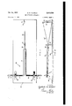
- FIG. 3 is a fragmentary elevation of the apparatus, partly in section, showing the invention employing optical indicating means
- Figure4 is an enlarged view of the indicating scale shown at the right hand portion of Figure 3.
- pipe line 2 carries drilling mud the density of which is to be measured to the measuring apparatus generally indicated at i 0 in Figure 1 and pipe line 4 carries the mud'away from the apparatus.
- the apparatus includes the U-shaped tubular member 12 having the extended leg portions l4 and 16.
- the leg portion 14 is joined to the pipe line 2 by the couplingfi and the leg portion [6 is joined to the pipe line 4 by a coupling 8.
- the leg members l4 and 16 are rigidly mounted within the mounting members l8 and 20 respectively.
- the members [8 and 20 are afiixed to the base plate 22.
- the apparatus may be included in a bleed-off line taken from the flow, line .to the well or in a bleed-off line taken from the discharge from the well or in both of these positions providing simultaneous indications of the weight or density of the mud both entering or leaving thewell.
- the tubing I2, [4 and l 6 is made of a material such as high carbon steel to provide suitable rigidity to prevent the tubular member from being deflected by the weight of the mud therein to a point at which it will take on a permanent set.
- Aflixed to the end of the hairpin loop is the member 24 which is adapted to bear upon one end of the lever arm 26.
- the leverarm 26 is pivotally mounted on the supporting post 28 which is, in turn, aiflxed to the base plate 22.
- Mounted adjacent to the other end of the lever arm 26 is the indicating scale 30 which is supported by the supporting member 32 aflixed to the base plate 22.
- the apparatus is arranged in such a fashion that the lever arm 26 will lie adjacent to the lowermost indication on the scale 30.
- the weight of the mud within the extended hairpin portion [2 .of the tubing will cause a torsional deflection in the extended tubular members I4 and I6 and a downward deflection of the hairpin portion 12.
- the member 24 will move downwardly causing the lever member 26 to assume, forconditions of maximum deflection, a position shown in construction lines at 26'. At this position the end of the lever 26 will lie adjacent to the uppermost mark on the scale 30.
- the deflection of the tubing will vary with the weight of the mud being passed through the tubing and the scale 39 may be readily calibrated to read directly in terms of both drilling mud weight and density.
- a lamp 36 providing a beam of light 40 which passes through the lenses38 through the aperture 42 and which, is reflected by the mirror 34 and focused upon the vertical scale 44.
- the reflected beam from the mirror 34 will travel along the path 46 and strike the indicating scale 44 at the uppermost point of its calibration.
- the mirror 34 will be moved downwardly to the maximum position shown in construction lines and indicated as 34'. With this position of the mirror the beam of light 40 will be deflected fromthe mirror along the path 45 and will strike the scale at its lowermost point of calibration.
- This invention provides a simple and practical apparatus which can be readily assembled in the field by the drilling crew for continuously indicating the weight of the drilling mud.
- the apparatus is simple and foolproof and it may be constructed with tube diameters as small as onehalf inch and with the lengths of the wishbone of approximately one foot.
- the invention should not be construed as limited by these proportions.
- the apparatus may be made portable thereby facilitating transportation and installation in the field.
- an apparatus which is not susceptible to plugging, jelling or channelling of the mud or to other similar problems generally encountered in the operation of conventional mud weighing apparatus.
- Apparatus for indicating the density of well drilling fluid comprising fluid conducting; means, said fluid conducting means including a substantially horizontally disposed conduit having a looped center portion and laterally extending end portions, said end portions of said conducting means being adapted to be connected to fluid supply means and fluid disposal means, means rigidly mounting said conducting means adjacent to said end portions thereof, and means indicating the displacement of the looped center portion of said fluid conducting means resulting from the deflection of said conducting means between said mounting means due to the weight of the fluid passing therethrough.
- Apparatus for indicating the density of well drilling fluid comprising fluid conducting means, said fluid conducting means comprising a substantially horizontally disposed conduit having a looped center portion and laterally extending end portions, said end portions of said conducting means being adapted to be connected to fluid supply means and fluid disposal means, means rigidly mounting said conducting means adjacent to said end portions thereof, and indicating means responsive to the displacement of the looped center portion of said fluid conducting means resulting from the deflection of said conducting means between said mounting means due to the Weight of the fluid passing therethrough for indicating the density of said fluid.
- Apparatus for indicating the density of well drilling fluid comprising fluid conducting means, said fluid conducting means including a substantially horizontally disposed conduit having a looped center portion and laterally extending end portions, said end portions of said conducting means being adapted to be connected to fluid supply means and fluid disposal means, means rigidly mounting said conducting means adjacent to said end portions thereof, and means indicating the displacement of the looped center portion of said fluid conducting means resulting from the deflection of said conducting means between said mounting means due to the weight of the fluid passing therethrough, said indicating means including a mirror movable by deflection of said looped center portion of the conduit, a light source and an indicating scale, said light source being adapted to project a beam of light upon the mirror and the indicating scale being positioned to receive the light beam reflected from the mirror to provide a greatly mags nified indication of deflection of said looped portion of said fluid conducting means resulting from the deflection of said conducting means between said mounting means due to the Weight of the fluid passing therethrough, said indicating means
Landscapes
- Physics & Mathematics (AREA)
- Health & Medical Sciences (AREA)
- Life Sciences & Earth Sciences (AREA)
- Chemical & Material Sciences (AREA)
- Analytical Chemistry (AREA)
- Biochemistry (AREA)
- General Health & Medical Sciences (AREA)
- General Physics & Mathematics (AREA)
- Immunology (AREA)
- Pathology (AREA)
- Earth Drilling (AREA)
Description
Oct. 14, 1952 Q R MCHOLS 2,613,530
MUD WEIGHING APPARATUS Filed Jan. 6, 1950 2 Sl-IEETS.-SHEET 1 FIG. 2.
1 INVENTOR. N N
CHARL ES R. NICHOLS ATTORNEY Oct. 14, 1952 I c R c g s 2,613,530
MUD WEIGHING'APPARATUS Filed Jan. 6, 1950 2 SHEETSSHEET 2 INVENTOR. CHARLES R. NICHOLS Patented Oct. 14, 1952 MUD WEIGHIN G APPARATUS Charles R. Nichols, McAllen; Tex., assignor to Sperry-Sun Well Surveying Company, Phila delphia, Pa., a corporation of Delaware Application January 6, 1950, Serial No. 137,067
This invention relates to a device for automatically and continuously indicating the density of well drilling fluid.
In drilling wells by the rotary method, drilling mud is circulated downthrough the drill pipe and up through the annular space between the drill pipe and borehole. The mud functions to remove the cuttings from the borehole, to preventcaving of the borehole wall and to provide sufficient hydrostatic pressure to overcome the pressure of the formations penetrated. A close control of the density of the drilling mud throughout the drilling operation is generally highly desirable. On the one hand, it is necessary that the weight of the drilling mud be sufiicient to provide a hydrostatic pressure adequate to hold back fluids such as gas or water in the formations encountered in order to prevent a blowout of the borehole. On the other hand, if the drilling mud becomes too heavy, the drilling fluid may be continuously forced into one or more of the formaweight of the circulating mud and prevent a' blowout. In some cases a variation in mud weight of only a small fraction of a pound per gallon may be sufficiently important to constitute the difference between satisfactory and unsatisfactory drilling progress. It is evident, therefore, that a continual accurate measurement of the mud density during the drilling operation is highly desirable.
Heretofore various devices have been employed in the measurement of density of drilling muds involving various degrees of complication. The principal difliculties encountered in the use of these mud weight indicator arise as a result of plugging or clogging of small lines or ports, jelling of the mud when circulation is arrested or when the mud lies static in parts of the apparatus, and channelling of the mud such as occurs when a portion of the mud in a container jells resulting in a restricted passage through which the mud flows.
These characteristics of drilling mud are'well known.
4 Claims. (01. 73 32) In my application Serial No. 7 7.397, filed February 19, 1949, there is disclose a device compris ing a U-shaped pipe having non-rigid mountings adjacent to the ends of the U and having the curved portion of the U supported by weighing means such as, for example, a conventional type of weighing scales. The weighing scales are set to a zero position when supporting only the weight of the empty pipe. When drilling mud is passed through the pipe, the weighing scale will provide an indication of the density of the mud.
It is an object of this invention to provide an improved means wherein the deflection of a pipe,
section under the load of the mud contained therein is employed for determining the weight and density of the mud within a U-shaped section of the pipe.
It is a further object of this invention to provide a mud weight indicator of such proportions as to be reasonably portable.
These and other objects of the invention will become apparent from the following description when read in conjunction with the accompanying drawing in which:
Figure 1 is a plan view of the apparatus involved employing mechanical indicating means;
Figure 2 is a side elevation of the apparatus shown in Figure 1;
Figure 3 is a fragmentary elevation of the apparatus, partly in section, showing the invention employing optical indicating means; and
Figure4 is an enlarged view of the indicating scale shown at the right hand portion of Figure 3.
Referring to Figures 1 and 2, pipe line 2 carries drilling mud the density of which is to be measured to the measuring apparatus generally indicated at i 0 in Figure 1 and pipe line 4 carries the mud'away from the apparatus. The apparatus includes the U-shaped tubular member 12 having the extended leg portions l4 and 16. The leg portion 14 is joined to the pipe line 2 by the couplingfi and the leg portion [6 is joined to the pipe line 4 by a coupling 8. The leg members l4 and 16 are rigidly mounted within the mounting members l8 and 20 respectively. The members [8 and 20 are afiixed to the base plate 22.,
The apparatus may be included in a bleed-off line taken from the flow, line .to the well or in a bleed-off line taken from the discharge from the well or in both of these positions providing simultaneous indications of the weight or density of the mud both entering or leaving thewell. .The tubing I2, [4 and l 6 is made of a material such as high carbon steel to provide suitable rigidity to prevent the tubular member from being deflected by the weight of the mud therein to a point at which it will take on a permanent set.
It should be noted that while the angle between the portions l2 and H of the tubing and that the angle between the portions 12 and i6 of the tubing are both drawn as approximately 96 angle, it is not necessary that the angle be restricted to 90. Various angles may be employed, the pertinent consideration being that the two angles be identical in order that the impact forces of fluids in the two bends will be balanced.
Aflixed to the end of the hairpin loop is the member 24 which is adapted to bear upon one end of the lever arm 26. The leverarm 26 is pivotally mounted on the supporting post 28 which is, in turn, aiflxed to the base plate 22. Mounted adjacent to the other end of the lever arm 26 is the indicating scale 30 which is supported by the supporting member 32 aflixed to the base plate 22. As will be observed in Figure 2 when the tubular member I2 is empty and unloaded, the apparatus is arranged in such a fashion that the lever arm 26 will lie adjacent to the lowermost indication on the scale 30. When drilling mud is passed through the tubular member the weight of the mud within the extended hairpin portion [2 .of the tubing will cause a torsional deflection in the extended tubular members I4 and I6 and a downward deflection of the hairpin portion 12. As a result of these deflections the member 24 will move downwardly causing the lever member 26 to assume, forconditions of maximum deflection, a position shown in construction lines at 26'. At this position the end of the lever 26 will lie adjacent to the uppermost mark on the scale 30. The deflection of the tubing will vary with the weight of the mud being passed through the tubing and the scale 39 may be readily calibrated to read directly in terms of both drilling mud weight and density.
It will be apparent that the mechanical indicating means previously described is but one of numerous types of indicating means Whichmay be employed and calibrated to provide direct readings of the density of fluid flowing through a pipe and causing the deflection of an extended portion thereof. An alternate form of indicator can be provided by the use of a beam of light as shown in Figure 3 wherein there is affixed to the end of the hairpin portion [2 of the tubular member a mirror 34 which, as the tubular member deflects, will assume a position at maximum deflection as shown in construction lines 34'.
With this type of indicator there is employed a lamp 36 providing a beam of light 40 which passes through the lenses38 through the aperture 42 and which, is reflected by the mirror 34 and focused upon the vertical scale 44. When there is no mud passing through the tubular member the reflected beam from the mirror 34 will travel along the path 46 and strike the indicating scale 44 at the uppermost point of its calibration. When the tubular member is carrying mud of maximum weight, the mirror 34 will be moved downwardly to the maximum position shown in construction lines and indicated as 34'. With this position of the mirror the beam of light 40 will be deflected fromthe mirror along the path 45 and will strike the scale at its lowermost point of calibration.
It will be understood that the present invention should not be limited to use with the mechanical or the optical types of indicating means described herein. Various other means for indicating defiection may be used, for example, electrical means may be employed wherein the deflection of the tubular member is adapted to cause a variation of a resistance, capacitance of inductance of an electrical element.
This invention provides a simple and practical apparatus which can be readily assembled in the field by the drilling crew for continuously indicating the weight of the drilling mud. The apparatus is simple and foolproof and it may be constructed with tube diameters as small as onehalf inch and with the lengths of the wishbone of approximately one foot. However, the invention should not be construed as limited by these proportions. Thus, the apparatus may be made portable thereby facilitating transportation and installation in the field. There is further provided an apparatus which is not susceptible to plugging, jelling or channelling of the mud or to other similar problems generally encountered in the operation of conventional mud weighing apparatus.
What is claimed is:
1. Apparatus for indicating the density of well drilling fluid comprising fluid conducting; means, said fluid conducting means including a substantially horizontally disposed conduit having a looped center portion and laterally extending end portions, said end portions of said conducting means being adapted to be connected to fluid supply means and fluid disposal means, means rigidly mounting said conducting means adjacent to said end portions thereof, and means indicating the displacement of the looped center portion of said fluid conducting means resulting from the deflection of said conducting means between said mounting means due to the weight of the fluid passing therethrough.
2. Apparatus for indicating the density of well drilling fluid comprising fluid conducting means, said fluid conducting means comprising a substantially horizontally disposed conduit having a looped center portion and laterally extending end portions, said end portions of said conducting means being adapted to be connected to fluid supply means and fluid disposal means, means rigidly mounting said conducting means adjacent to said end portions thereof, and indicating means responsive to the displacement of the looped center portion of said fluid conducting means resulting from the deflection of said conducting means between said mounting means due to the Weight of the fluid passing therethrough for indicating the density of said fluid.
3. Apparatus for indicating the density of well drilling fluid comprising fluid conducting means, said fluid conducting means including a substantially horizontally disposed conduit having a looped center portion and laterally extending end portions, said end portions of said conducting means being adapted to be connected to fluid supply means and fluid disposal means, means rigidly mounting said conducting means adjacent to said end portions thereof, and means indicating the displacement of the looped center portion of said fluid conducting means resulting from the deflection of said conducting means between said mounting means due to the weight of the fluid passing therethrough, said indicating means including a mirror movable by deflection of said looped center portion of the conduit, a light source and an indicating scale, said light source being adapted to project a beam of light upon the mirror and the indicating scale being positioned to receive the light beam reflected from the mirror to provide a greatly mags nified indication of deflection of said looped portion of said fluid conducting means resulting from the deflection of said conducting means between said mounting means due to the Weight of the fluid passing therethrough, said indicating means including a mirror mounted on said looped center portion of the conduit and movable therewith, a light source and an indicating scale, said light source being adapted to project a beam of light upon the mirror and the indicating scale being positioned to receive the light beam reflected from the mirror to provide a greatly magnified indication of deflection of said looped center portion of the conduit.
CHARLES R. NICHOLS.
REFERENCES CITEK) The following references are of record in the file of this patent:
UNITED STATES PATENTS Number Name Date 1,511,604 Ganucheau Oct. 14, 1924 1,939,161 Bestelmeyer Dec. 12, 1933 2,284,060 Knauth May 26, 1942 2,311,312 Marsh Feb. 16, 1943 2,366,194 Kaiser Jan. 2, 1945 2,432,039 Plank Dec. 2, 1947
Priority Applications (1)
| Application Number | Priority Date | Filing Date | Title |
|---|---|---|---|
| US137067A US2613530A (en) | 1950-01-06 | 1950-01-06 | Mud weighing apparatus |
Applications Claiming Priority (1)
| Application Number | Priority Date | Filing Date | Title |
|---|---|---|---|
| US137067A US2613530A (en) | 1950-01-06 | 1950-01-06 | Mud weighing apparatus |
Publications (1)
| Publication Number | Publication Date |
|---|---|
| US2613530A true US2613530A (en) | 1952-10-14 |
Family
ID=22475694
Family Applications (1)
| Application Number | Title | Priority Date | Filing Date |
|---|---|---|---|
| US137067A Expired - Lifetime US2613530A (en) | 1950-01-06 | 1950-01-06 | Mud weighing apparatus |
Country Status (1)
| Country | Link |
|---|---|
| US (1) | US2613530A (en) |
Cited By (10)
| Publication number | Priority date | Publication date | Assignee | Title |
|---|---|---|---|---|
| US2775893A (en) * | 1953-12-07 | 1957-01-01 | Ethbert R Nett | Density indicating apparatus |
| US2838927A (en) * | 1955-03-29 | 1958-06-17 | American Meter Co | Gas density measuring device |
| US2987913A (en) * | 1956-02-08 | 1961-06-13 | Honeywell Regulator Co | Pointer mechanism improvements |
| DE1182879B (en) * | 1958-05-24 | 1964-12-03 | Wintershall Ag | Device for continuous measurement of the true density of aqueous solid-liquid mixtures, in particular aqueous salt solutions |
| US4285239A (en) * | 1980-05-01 | 1981-08-25 | Heine Otto R | Apparatus for measuring varying density of a slurry flowing in a pipeline |
| US4476722A (en) * | 1982-09-29 | 1984-10-16 | Scientific Resources, Inc. | Continuously monitoring and self-cleaning liquid density measurement system |
| US7290447B1 (en) * | 2003-10-07 | 2007-11-06 | Bj Services Company | Density measuring apparatus containing a densimeter and a method of using the same in a pipeline |
| US20140041451A1 (en) * | 2010-03-31 | 2014-02-13 | Kim A. Hodgson | Non-Radioactive Density Measurement In Oilfield Operations |
| US8915145B1 (en) | 2013-07-30 | 2014-12-23 | Fred G. Van Orsdol | Multiphase mass flow metering system and method using density and volumetric flow rate determination |
| ITGE20130123A1 (en) * | 2013-12-20 | 2015-06-21 | Ecomin Srl | METHOD FOR DETERMINING THE DENSITY OF FLUIDS AND DEVICE FOR ITS IMPLEMENTATION |
Citations (6)
| Publication number | Priority date | Publication date | Assignee | Title |
|---|---|---|---|---|
| US1511604A (en) * | 1923-05-21 | 1924-10-14 | James J Ganucheau | Specific-gravity apparatus |
| US1939161A (en) * | 1930-07-24 | 1933-12-12 | Hartmann & Braun Ag | Apparatus for optical transfer of measurements |
| US2284060A (en) * | 1941-06-16 | 1942-05-26 | Walter T Knauth | Means for measuring and recording liquid density |
| US2311312A (en) * | 1941-02-17 | 1943-02-16 | Socony Vacuum Oil Co Inc | Continuous mud weight indicator |
| US2366194A (en) * | 1945-01-02 | Arrangement fob photographically | ||
| US2432039A (en) * | 1946-02-25 | 1947-12-02 | Shell Dev | Device for measuring the density of fluids in pipes |
-
1950
- 1950-01-06 US US137067A patent/US2613530A/en not_active Expired - Lifetime
Patent Citations (6)
| Publication number | Priority date | Publication date | Assignee | Title |
|---|---|---|---|---|
| US2366194A (en) * | 1945-01-02 | Arrangement fob photographically | ||
| US1511604A (en) * | 1923-05-21 | 1924-10-14 | James J Ganucheau | Specific-gravity apparatus |
| US1939161A (en) * | 1930-07-24 | 1933-12-12 | Hartmann & Braun Ag | Apparatus for optical transfer of measurements |
| US2311312A (en) * | 1941-02-17 | 1943-02-16 | Socony Vacuum Oil Co Inc | Continuous mud weight indicator |
| US2284060A (en) * | 1941-06-16 | 1942-05-26 | Walter T Knauth | Means for measuring and recording liquid density |
| US2432039A (en) * | 1946-02-25 | 1947-12-02 | Shell Dev | Device for measuring the density of fluids in pipes |
Cited By (11)
| Publication number | Priority date | Publication date | Assignee | Title |
|---|---|---|---|---|
| US2775893A (en) * | 1953-12-07 | 1957-01-01 | Ethbert R Nett | Density indicating apparatus |
| US2838927A (en) * | 1955-03-29 | 1958-06-17 | American Meter Co | Gas density measuring device |
| US2987913A (en) * | 1956-02-08 | 1961-06-13 | Honeywell Regulator Co | Pointer mechanism improvements |
| DE1182879B (en) * | 1958-05-24 | 1964-12-03 | Wintershall Ag | Device for continuous measurement of the true density of aqueous solid-liquid mixtures, in particular aqueous salt solutions |
| US4285239A (en) * | 1980-05-01 | 1981-08-25 | Heine Otto R | Apparatus for measuring varying density of a slurry flowing in a pipeline |
| US4476722A (en) * | 1982-09-29 | 1984-10-16 | Scientific Resources, Inc. | Continuously monitoring and self-cleaning liquid density measurement system |
| US7290447B1 (en) * | 2003-10-07 | 2007-11-06 | Bj Services Company | Density measuring apparatus containing a densimeter and a method of using the same in a pipeline |
| US20140041451A1 (en) * | 2010-03-31 | 2014-02-13 | Kim A. Hodgson | Non-Radioactive Density Measurement In Oilfield Operations |
| US9625364B2 (en) * | 2010-03-31 | 2017-04-18 | Schlumberger Technology Corporation | Non-radioactive density measurement in oilfield operations |
| US8915145B1 (en) | 2013-07-30 | 2014-12-23 | Fred G. Van Orsdol | Multiphase mass flow metering system and method using density and volumetric flow rate determination |
| ITGE20130123A1 (en) * | 2013-12-20 | 2015-06-21 | Ecomin Srl | METHOD FOR DETERMINING THE DENSITY OF FLUIDS AND DEVICE FOR ITS IMPLEMENTATION |
Similar Documents
| Publication | Publication Date | Title |
|---|---|---|
| US2613530A (en) | Mud weighing apparatus | |
| CN210487017U (en) | Circulating tank mud liquid level monitoring device | |
| US2432039A (en) | Device for measuring the density of fluids in pipes | |
| US2517603A (en) | Fluid ingress well logging | |
| US2701960A (en) | Apparatus for detecting leaks | |
| EP0114865B1 (en) | Apparatus for determining borehole or cavity configuration through inert gas interface | |
| US3911741A (en) | Pneumatic fluid weighing device | |
| US3473368A (en) | Method and apparatus for continuously monitoring properties of thixotropic fluids | |
| NO178206B (en) | Method and apparatus for measuring density and pressure loss in a flowing liquid | |
| US4485675A (en) | Pneumatic fluid densiometer | |
| US2669118A (en) | Apparatus for mud weight determination | |
| US2618156A (en) | Gravity and density gradiometer for boreholes | |
| US1042248A (en) | Surveying instrument. | |
| US2688868A (en) | Specific gravity meter | |
| US3874231A (en) | Diffusion barrier chamber for sperry sun permagage type pressure gage | |
| US2132736A (en) | Drilling fluid tester scale | |
| US2528956A (en) | Detection of washouts in rotary drilling strings | |
| US2729897A (en) | Instrument for transferring survey reference points | |
| US3064468A (en) | Method and apparatus for measuring properties of fluid | |
| US2855780A (en) | Apparatus for bottom-hole pressure measurement | |
| US1971610A (en) | Recording hydrometer | |
| CN205422692U (en) | Portable drilling angular instrument | |
| US2235064A (en) | Determination of densities of fluids in wells | |
| US2945952A (en) | Method and apparatus for locating producing zones in wells | |
| US2353619A (en) | Geophysical prospecting |