US2611625A - Independent front wheel suspension coupled as a unit to the vehicle frame - Google Patents
Independent front wheel suspension coupled as a unit to the vehicle frame Download PDFInfo
- Publication number
- US2611625A US2611625A US664632A US66463246A US2611625A US 2611625 A US2611625 A US 2611625A US 664632 A US664632 A US 664632A US 66463246 A US66463246 A US 66463246A US 2611625 A US2611625 A US 2611625A
- Authority
- US
- United States
- Prior art keywords
- secured
- apertures
- extending
- control arm
- arm
- Prior art date
- Legal status (The legal status is an assumption and is not a legal conclusion. Google has not performed a legal analysis and makes no representation as to the accuracy of the status listed.)
- Expired - Lifetime
Links
Images


Classifications
-
- B—PERFORMING OPERATIONS; TRANSPORTING
- B60—VEHICLES IN GENERAL
- B60G—VEHICLE SUSPENSION ARRANGEMENTS
- B60G3/00—Resilient suspensions for a single wheel
- B60G3/18—Resilient suspensions for a single wheel with two or more pivoted arms, e.g. parallelogram
- B60G3/20—Resilient suspensions for a single wheel with two or more pivoted arms, e.g. parallelogram all arms being rigid
-
- B—PERFORMING OPERATIONS; TRANSPORTING
- B60—VEHICLES IN GENERAL
- B60G—VEHICLE SUSPENSION ARRANGEMENTS
- B60G3/00—Resilient suspensions for a single wheel
- B60G3/18—Resilient suspensions for a single wheel with two or more pivoted arms, e.g. parallelogram
-
- B—PERFORMING OPERATIONS; TRANSPORTING
- B60—VEHICLES IN GENERAL
- B60G—VEHICLE SUSPENSION ARRANGEMENTS
- B60G7/00—Pivoted suspension arms; Accessories thereof
- B60G7/001—Suspension arms, e.g. constructional features
-
- B—PERFORMING OPERATIONS; TRANSPORTING
- B60—VEHICLES IN GENERAL
- B60G—VEHICLE SUSPENSION ARRANGEMENTS
- B60G7/00—Pivoted suspension arms; Accessories thereof
- B60G7/02—Attaching arms to sprung part of vehicle
-
- B—PERFORMING OPERATIONS; TRANSPORTING
- B60—VEHICLES IN GENERAL
- B60G—VEHICLE SUSPENSION ARRANGEMENTS
- B60G7/00—Pivoted suspension arms; Accessories thereof
- B60G7/04—Buffer means for limiting movement of arms
-
- B—PERFORMING OPERATIONS; TRANSPORTING
- B62—LAND VEHICLES FOR TRAVELLING OTHERWISE THAN ON RAILS
- B62D—MOTOR VEHICLES; TRAILERS
- B62D21/00—Understructures, i.e. chassis frame on which a vehicle body may be mounted
- B62D21/02—Understructures, i.e. chassis frame on which a vehicle body may be mounted comprising longitudinally or transversely arranged frame members
-
- B—PERFORMING OPERATIONS; TRANSPORTING
- B60—VEHICLES IN GENERAL
- B60G—VEHICLE SUSPENSION ARRANGEMENTS
- B60G2200/00—Indexing codes relating to suspension types
- B60G2200/10—Independent suspensions
- B60G2200/14—Independent suspensions with lateral arms
- B60G2200/144—Independent suspensions with lateral arms with two lateral arms forming a parallelogram
-
- B—PERFORMING OPERATIONS; TRANSPORTING
- B60—VEHICLES IN GENERAL
- B60G—VEHICLE SUSPENSION ARRANGEMENTS
- B60G2204/00—Indexing codes related to suspensions per se or to auxiliary parts
- B60G2204/10—Mounting of suspension elements
- B60G2204/12—Mounting of springs or dampers
- B60G2204/124—Mounting of coil springs
- B60G2204/1244—Mounting of coil springs on a suspension arm
-
- B—PERFORMING OPERATIONS; TRANSPORTING
- B60—VEHICLES IN GENERAL
- B60G—VEHICLE SUSPENSION ARRANGEMENTS
- B60G2204/00—Indexing codes related to suspensions per se or to auxiliary parts
- B60G2204/10—Mounting of suspension elements
- B60G2204/14—Mounting of suspension arms
- B60G2204/143—Mounting of suspension arms on the vehicle body or chassis
-
- B—PERFORMING OPERATIONS; TRANSPORTING
- B60—VEHICLES IN GENERAL
- B60G—VEHICLE SUSPENSION ARRANGEMENTS
- B60G2204/00—Indexing codes related to suspensions per se or to auxiliary parts
- B60G2204/10—Mounting of suspension elements
- B60G2204/15—Mounting of subframes
-
- B—PERFORMING OPERATIONS; TRANSPORTING
- B60—VEHICLES IN GENERAL
- B60G—VEHICLE SUSPENSION ARRANGEMENTS
- B60G2204/00—Indexing codes related to suspensions per se or to auxiliary parts
- B60G2204/40—Auxiliary suspension parts; Adjustment of suspensions
- B60G2204/41—Elastic mounts, e.g. bushings
-
- B—PERFORMING OPERATIONS; TRANSPORTING
- B60—VEHICLES IN GENERAL
- B60G—VEHICLE SUSPENSION ARRANGEMENTS
- B60G2204/00—Indexing codes related to suspensions per se or to auxiliary parts
- B60G2204/40—Auxiliary suspension parts; Adjustment of suspensions
- B60G2204/45—Stops limiting travel
- B60G2204/4502—Stops limiting travel using resilient buffer
-
- B—PERFORMING OPERATIONS; TRANSPORTING
- B60—VEHICLES IN GENERAL
- B60G—VEHICLE SUSPENSION ARRANGEMENTS
- B60G2206/00—Indexing codes related to the manufacturing of suspensions: constructional features, the materials used, procedures or tools
- B60G2206/01—Constructional features of suspension elements, e.g. arms, dampers, springs
- B60G2206/10—Constructional features of arms
-
- B—PERFORMING OPERATIONS; TRANSPORTING
- B60—VEHICLES IN GENERAL
- B60G—VEHICLE SUSPENSION ARRANGEMENTS
- B60G2206/00—Indexing codes related to the manufacturing of suspensions: constructional features, the materials used, procedures or tools
- B60G2206/01—Constructional features of suspension elements, e.g. arms, dampers, springs
- B60G2206/60—Subframe construction
-
- Y—GENERAL TAGGING OF NEW TECHNOLOGICAL DEVELOPMENTS; GENERAL TAGGING OF CROSS-SECTIONAL TECHNOLOGIES SPANNING OVER SEVERAL SECTIONS OF THE IPC; TECHNICAL SUBJECTS COVERED BY FORMER USPC CROSS-REFERENCE ART COLLECTIONS [XRACs] AND DIGESTS
- Y10—TECHNICAL SUBJECTS COVERED BY FORMER USPC
- Y10T—TECHNICAL SUBJECTS COVERED BY FORMER US CLASSIFICATION
- Y10T403/00—Joints and connections
- Y10T403/32—Articulated members
- Y10T403/32606—Pivoted
- Y10T403/32631—Universal ball and socket
- Y10T403/32681—Composite ball
- Y10T403/32704—Stud extends into ball
-
- Y—GENERAL TAGGING OF NEW TECHNOLOGICAL DEVELOPMENTS; GENERAL TAGGING OF CROSS-SECTIONAL TECHNOLOGIES SPANNING OVER SEVERAL SECTIONS OF THE IPC; TECHNICAL SUBJECTS COVERED BY FORMER USPC CROSS-REFERENCE ART COLLECTIONS [XRACs] AND DIGESTS
- Y10—TECHNICAL SUBJECTS COVERED BY FORMER USPC
- Y10T—TECHNICAL SUBJECTS COVERED BY FORMER US CLASSIFICATION
- Y10T403/00—Joints and connections
- Y10T403/32—Articulated members
- Y10T403/32606—Pivoted
- Y10T403/32631—Universal ball and socket
- Y10T403/32803—Separable socket sections
-
- Y—GENERAL TAGGING OF NEW TECHNOLOGICAL DEVELOPMENTS; GENERAL TAGGING OF CROSS-SECTIONAL TECHNOLOGIES SPANNING OVER SEVERAL SECTIONS OF THE IPC; TECHNICAL SUBJECTS COVERED BY FORMER USPC CROSS-REFERENCE ART COLLECTIONS [XRACs] AND DIGESTS
- Y10—TECHNICAL SUBJECTS COVERED BY FORMER USPC
- Y10T—TECHNICAL SUBJECTS COVERED BY FORMER US CLASSIFICATION
- Y10T403/00—Joints and connections
- Y10T403/32—Articulated members
- Y10T403/32606—Pivoted
- Y10T403/32631—Universal ball and socket
- Y10T403/32811—Spring-biased
-
- Y—GENERAL TAGGING OF NEW TECHNOLOGICAL DEVELOPMENTS; GENERAL TAGGING OF CROSS-SECTIONAL TECHNOLOGIES SPANNING OVER SEVERAL SECTIONS OF THE IPC; TECHNICAL SUBJECTS COVERED BY FORMER USPC CROSS-REFERENCE ART COLLECTIONS [XRACs] AND DIGESTS
- Y10—TECHNICAL SUBJECTS COVERED BY FORMER USPC
- Y10T—TECHNICAL SUBJECTS COVERED BY FORMER US CLASSIFICATION
- Y10T74/00—Machine element or mechanism
- Y10T74/20—Control lever and linkage systems
- Y10T74/20576—Elements
- Y10T74/20882—Rocker arms
Definitions
- This invention relates to wheel -suspensions and more particularly to an independent front wheel suspension for automobiles.
- v Y It is an object of this invention to provide-an independent wheel suspension for a vehicle which is simple and economical to manufacture.
- Y ⁇ It is another object of this invention to provid-e anindependent wheel suspension for a vehicle which will be completely assembled and adjusted before it is secured to-the body of thevehicle.v
- f Y f n -It is a further object of this invention to provide an independent wheel suspension for a vehicle which will provide a smoother ride to the occupants of the vehicle and also'easier steering of said vehicle.
- Figure 1 is a front elevational view of the invention as applied to the front wheels of an automobile; .v
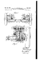
- Figure 2 is a view similar to Figure 1 but enlarged and partially insection and Ashowing the invention as applied to only one wheel of an automobile
- Figure 3 is a top plan view-of, the'frame crossimember of the invention to Whic'h'is attached a portion of the steering mechanism and wheel carrying means of the invention;
- Figure 4 a front elevational view of the cross member shown in Figure 3;
- I Figure 5 is a sectonal-view'taken along the lines 5 5 of Figure 4 ⁇ and looking in the direction of the arrows;
- Figure 6 is aside elevational view of the upper-4 control-arm-carrying member ;A b
- Figure 8 is a top view of the lower control arm;
- Figure 9 is a side elevationalvew of the control arm shown in Figure 8;
- Figure 10 is a sectional view of the control arm shown in Figure 9 taken along the lines III-I0 of Figure 9 and looking in the direction of the arrows;
- Figure 11 is a top view of the upper control arm of the invention.
- Kenosha, Wis., acor- : Figure 12 is a sideelevational view of the upper control arm shown in : Figure 11;
- Figure 13 is a sectional View of the upper control arm taken along lines I3-I3 of Figure ⁇ 12 and looking in thedirection 'of the arrows;
- v Figure 14 is an enlarged View of theinvention as shown in Figure 2.
- f i' Referring in. detail to the drawings, the yinvention as shown in Figure 1 -isapplied to both of the front whee1s'2 vof an automobile and cornprises a rigid cross member 4 extending between the wheels 2 to which/is rotatively secured the lower control .arms 6.
- the control arms Bare secured at their inner ends lto crossmember 4 by bolts 8.
- Y Cross member '4 ifs fprovided with' a pair of towers IU on thev top of which vare secured uppercontrol-arm-carrying'members l2.
- lMembers I2 carry the rupper control arms I4, the inner ends of which are rotatably secured to the members I2.
- f Wheel carrying pins I6 are positioned between i the outer ends of lower control arms E and upper control .arms lI4 andare rotatably secured to the upper arms '6 by ball'and socket-joints indicated generally at I8 ( Figures 1 andZ) vand are rotatably secured to lthe lower contro1 arms 6 by trunnion connections indicated generally at 20 ( Figures1and2).
- the Wheel 'spindles 22 on which 4the wheels 2 are mounted have portions extending through apertures in'pinsgl and nuts 24 are threaded on'jsaid portions to l1 igid1ysecu ⁇ re spindles 22 to pins I6.
- To lupperc'ontrol arms I4 are secured rubber bumpers 26 which strikel members I2 when Wheels 'lare lowerede'xcessively.
- ⁇ Sheet metal ⁇ stampings 28 are secured to the top of cross memberll to brace towers YI Il and also aid 'in securing the 'cross memberv 4 to the side rails 30 of the automobile frame. Stampings 32 are securedti) the top yofcrossmember 4 and spaced from stampings 28 a distance suicient to permit side rails 30 of theframe to .be placed therebetween. Wheelhousing's ⁇ 34 extend downwardly andI are'secured to rails 3Q between said rails'and ⁇ stampings '28.
- connection I8 which connectsv the pinfl 6 :te
- Aupper control armlll is'a ball'and socket joint consisting yof asocket-like'fmember 42 formednear the outer end of arm I4.
- a lubricating valve 44 for lubrication of connection I8.
- member 42 On the inner surface of member 42 is .posif' tioned a bearing 46 within which is positioned a partially spherical member 48. Member 48 has an aperture extending through the center there--n .e
- a ball retainery 52 is positioned around reduced portion 50 of pin I6 and is secured to control arm material.
- ] isinsulated in regard to the cross
- Retainer 52 is provided with a bearing 54 designed r-to extend inwardly into engagement with ball member 43 on its lower surface to hold member 48 in engagement with the upper bearing 46.
- positioned around reduced portion 56 is a cuplike member 56 which is adapted to frictionallyY engage the lower sphericalsurface of retainer 52 to prevent dirt, etc. from entering the ball and socket connection I8.
- Cuplike member 56 iscon- ⁇ stantly urged upwardly into engagement with retainer 52 vby compression spring 53 which is interposed between cuplike member 56 andthe enlarged central portion of pin
- Pin I6 is provided with a second reduced portion 62 formed near its lower-end. Around'reduced portion 62 is positioned a trunnion member 64. A metal .ring 66 is positioned around portion 62 between trunnion 64 andthe lower end of the enlarged porti'on-ofpin I6.
- a third reduced portion 66 adjacent portion 62 is formed on pin I6 immediately below portion 62 and has a ball bearing 'I0 positioned there.-v around on which trunnion 64 is carried.
- portion 68 Immediately below portion 68 .is formed a fcurthreduced portion 'I2 of pin I6.
- Portion ⁇ 'I2 is threaded and provided with a washer 'I4 im-f mediately below bearing 16 to' carry said bearing.
- This assembled connection is secured on the lower end of pin I6 by a nut 16 which is turnedon threaded portion 'I2 and held in a fixed position thereon by a pin which extends through, aperture I8 in the lower end of piny I6.
- 4 extends inwardly from connection
- l v j A trunnion member 80 having its vends extending through apertures
- -bolts 82 On the outer end of -bolts 82 are positioned 'lock washers 88 and nuts 90 to form a rig-id connection betweenl trunnionfmember 86 andk theemember I2. Shims 84 are positioned between Vtrunnion 8i) and member I2 to adjust the caster. and camber of the wheels 2. -It will be noted thatas the inner ends of member
- Rubber bumper26 is secured .adjacent ;the underside of raised portion
- ]V of' theV comprised of a bolt 36 extending -rst through an member 4."
- the inner end of bolt 36 is provided with a nut A38 which holds this .connection together.
- Tower IIl extends upwardly Vthrough, aligned iianged apertures in-the bottom and top of cross member 4 ⁇ and at its bottom has a radially extending peripheralgflange
- the aperture in the bottom of cross member 4through which tower I6 extends is defined by anupwardly extending pe ripheral flange
- the aperture ⁇ in the ⁇ top of cross member, 4 through which tower I0 extends is defined by an upwardly extending peripheral flange I
- Nearithetop of tower I8 said tower is provided with a rst reduced portion
- I ⁇ is formed a second and further reduced portion
- Withinportion .I I8 of tower I0 is positioned a metal sleeve
- 22 is positioned an insulator
- Within tower. I0 is positioned a compression spring
- 30 is positioned around a tower
- Spring I28 is retained in this manner between the topof towerA I0 and controlar-m 6 in a slightly compressed rstate and is subject to further compression when the wheels 2.are moved upwardly, thus providing-a cushioned ⁇ ride for the vehicle.
- I2 Secured at its top in acrown
- I2 is-a shock absorber
- 36 is provided with a bolt 38 extending therefrom through an aperturc I46..(, Figures 6 and VrI).
- 40 isy first. positioned a cup-like washer
- 36 extends ydownwar-dly through an aperture
- 3'6 extends downwardly substantially through the center of spring
- 58 is secured to crown
- 60 defines a crown
- 60 is secured to control arm 6 by bolts
- 62 extends upwardly through aperture
- the upper control arm I4 is shown in detail in Figures 11, 12 and 13.
- 4 i is composed of Ia pair of channel portions
- 12 ( Figure 12) extends around the outer end portion
- 18 are in alignment with apertures
- 10 is provided with a raised portion
- web portion 16 is provided with thesocket member 42 which Elias been described hereinbefore in relation to Figure 2.
- '10 is further provided with apertures
- upper -control -arm I4 may be stamped out of a single piece of sheet metal.
- Lower control arm 6 is shown in detail Figures 8, 9 and 10, and is like upper control arm
- 94 are each provided with an outwardly extending ange
- 98 ina like manner are terminated near the outer end 204 of' portions
- 32 as described before in connect-ion with FigureA y2 is provided in itstop with an aperture
- 32 is further provided with apertures 2 llwhich are adapted to receive bolts
- 92 is provided with raised ribs 2
- 0 is provided with an :aperture 2
- 4, may be stamped from a singlepiece of sheet metal.
- 2 is shown in detail in Figures 6 and 7.
- 2 is comprised of a lower stamping '220 whi-ch isprovided with a flat base portion 222 designed to rest on the top of ⁇ tower I0 ( Figures 1 and l2).
- Stamping 220 is provi-ded with a rstupwardly extending portion 224 and a vertical inner portion y226 defining its yinn-er end.
- member 220 is designed basically similar to the upper and lower control arms in that it is composed of a pair of spaced channel portions 228 which extend outwardly and nearly converge at their outer ends.
- Channel portions 228 are provided with anges 230 extending outwardly and inner iianges 232. Near the inner and upper ends 234 of portions 228 are provided flanged apertures 236. The channel portions 228 are upwardlyopened and the second stamping 238 of member
- Stamping 238 has a pair of downwardly open channel portions 240 which are provided with outwardly extending iianges 242 and inwardly extending flanges 244.
- the channel portions 240, angesv 242 and flanges 244 of member 238 are designed to completely cover channel portion 228,
- Portions 240 of member238 are provided near their -upper ends 245 with flanged apertures 248 which are in alignment v with apertures .236 of member 226. These apertures'2 36 and 248 are designed to receive the bolts 82 ( Figure 2) which carry the trunnionmember 66 ( Figure2). which in turn-.carries the control arm I4.
- .Member 12 is provided with a tube member .86 extending between each pair of apertures 236 and 248and surrounding the iianges thereof. Members 86 are provided to strengthen member 12, maintain said apertures in spaced relation and form a housing-for boltsv82. i
- Adjacent tower 134 and opposite apertures 254, web 250 of member 238 is provided with a pair of flanged apertures 256 which are in alignment with a pair of flanged apertures258iormed in portion 222 of member 226.
- Aligned apertures 252 and 254 are designed to receive bolts ⁇ which will secure member 12 to the top of tower 10 ( Figurer l).
- Alignedapertures 256 and 258 perform a like function.
- Each pair of apertures 256 and 258 are provided with a tubular member 251 extending therebetween similar in form and function to tube members 36.
- Cross member 4 which extends between and carries the front wheels ofv the'vehicle is shown in detail in Figures 3, 4 and 5.
- Cross member 4 is composed of a channel member 260 ( Figure 5) having a bottom 262, a,V substantially vertical front wall 264, a vertical rea-r wall 265 and a horizontal flange 268 extending, around the entire periphery of member 260.
- Channel member 263 is provided with a cover plate 216 which is secured to the flange 268 by welding or other suitable means.
- Cover 210 is provided with a pair of elongated depressions 212 each extending from approximately the center of member 216 towards its ends. Depressions 212 are provided for additional strength.
- A-shaped stamping 214 having its top abutting cover 219 and its legs secured to the bottom 262 of member 263.
- A-shaped stamping 214 extends between the towers and is provided to strengthen the cross member 4.
- member ⁇ 214 In the sides of member 214 are formed av series of spaced depressions-216 whichA make the member 214 more rigid. At spaced intervals between the depressions 216, member ⁇ 214 is providedY with a series of apertures 218.
- stamping 286 On its underside at its center, 'cross member il is provided with a stamping 286 which is provided with a downwardly extending peripheral flange 262. Stamping 239 is riveted to the bottom 262 of channel member26. Stamping 280 is provided with a'flange aperture 234 in which is positioned and rigidly secured a sleeve 286'which extends upwardly through a flanged. aperture 283' which is formed in the' bottom of the Well' 266 which is stamped downwardly in the cover member 21:3. Sleeve 286 is rigidly secured within these: apertures by welding and a pair of bearings 292 are positioned withinthe sleeve.
- Bolt 295 (Figure 3) extends downwardly through the bearings 2.92 below cross member 4 and has journaled on its lowerend the idler arm 296vof the steering mechanism of the vehicle.
- the ⁇ idler r.arm 23S hasits inner end positioned vwithin theange 262 ( Figure 5) .of member. 280 and isprovided with a pair of ears 298.
- dler arm..l 235 extends backwardly from boltv :294 througha cutoutportion 306 of the member 280 to its rearmost end to which is rotatably secured the inner end of the manually controlled steering drag link 295 and the inner ends of steering.
- tie rods 291.v The outerVv ends of tie rods 291 are rotatably secured to steering armsl 299 portions of which are rigidly secured between wheelpins 16 and spindles 22 of each wheel 2 in a substantiallyhorizontal position by nuts 24 ( Figures l and 2) so that pins 16 may be rotated thereby.
- This steering mechanism is manually controlled through the'arm 301 which is rotatably secured to the outer end of link ⁇ 235 and is oscillated to pull'and. push link 295 ⁇ by Aenergy transmitted thereto through gears in housing 363 to which is securedrthe lower end of steering column 305 adjacent the upper end of which is positioned the usualvhand steering wheel. This provides the steering mechanism for the automobile.
- Shafts 332 are positioned within aligned ,apertures in walls 264 and 26E of cross member. 4k and have threaded ends 364 ( Figure 3) around which the inner endsof thelower control arms 6 are telescopically,positioned. Washers A.'it are positioned around each end ofthe shafts 332 and abut the adjacent walls 264 and 266 of cross member 1.
- YStampings 28 as shown in Figures l, 3 and 4 are provided with outwardly turned portions 312 which have cutout portions 311i designed toffit the outer periphery of the towers 1l). Stampings 28 arewelded to the cover 211)- of the cross member 4 and portions 314 of stampings 28 are welded to the towers ⁇ 1U. In this manner additional support is provided for said towers. 32 are also. secured to Acover 216 as'by welding.
- An independent wheel suspension .for a vehicle comprising a frame cross member, aligned apertures formed in the top and bottom of said cross member adjacent its end, a cylindrical member having apartially closed top secured' within said aligned apertures and extending upwardly therefrom, va lower control arm rotatably. secured to said cross member and extending outwardly therefrom, an upper control arm rotatably secured to said cylindrical member and extending Stampings tires outwardly therefrom, a wheel carrying member extending between the outer ends of said upper and lower control arms and rotatably secured thereto, and a compression spring interposed between and abutting said lower control arm and the top of said cylindrical member.
- An independent wheel suspension for a vehicle comprising a frame, a frame cross member resiliently secured to said frame, aligned apertures formed in the top and bottom of said cross member adjacent the end thereof, a cylindrical member telescopically positioned within said aligned apertures and ex-tending upwardly therefrom and having a partially closed top, a lower control arm rotatably secured to said cross member and extending outwardly therefrom, an upper control arm, means secured to the top of said cylindrical member and rotatably carrying said upper control arm, a wheel carrying member extending between the outer ends of said upper control arm and said lower control arm, and a compression spring interposed between and abutrting said lower control arm and the top of said cylindrical member.
- An independent wheel suspension comprising a resiliently mounted frame cross member, aligned apertures formed in the top and bottom of said cross member, a cylindrical member rigidly secured within said aligned apertures and extending upwardly therefrom, a lower control arm rotatably secured to said cross member and extending outwardly therefrom, an outwardly extending upper control arm, means secured to said cylindrical member for rotatably carrying said upper control arm, Wheel carrying means interposed between the outer ends of said upper and lower control arms, a first spring seat formed in the top of said cylindrical member, a second spring seat formed in said lower control arm, and. a compression spring interposed between and abutting said spring seats.
- An independent wheel suspension for a Vehicle comprising a frame cross member, aligned apertures formed in the top and bottom of said cross member and adjacent to its outer end, a cylindrical member rigidly secured within said apertures and extending upwardly therefrom and having a partially closed upper end, a lower control arm rotatably secured to said cross member and extending outwardly therefrom, an upper control arm, means secured to said cylindrical member for rotatably carrying said upper control arm, wheel carrying means extending between the outer ends of said upper and lower control arms and rotatably secured thereto, a spring seat formed on said lower control arm, a spring seat positioned within said cylindrical member below its upper end. and a compression spring interposed between and abutting said spring seats.
- An independent wheel suspension comprising a resiliently mounted frame cross member, aligned apertures formed in the upper and lower walls of said cross member, a cylindrical member positioned and secured within said apertures 10 and extending upwardly therefrom and havi a partially closed upper end, an outwardly extending upper control arm, a lower control arm rotatably secured to said cross member and extending outwardly therefrom, means secured to the upper end of said cylindrical member for rotatably carrying said upper control arm, a spring seat secured within the upper end of said cylindrical member, a spring seat formed in said lower control arm, a spring interposed between and abutting said spring seats, and a shock absorber extending through said spring and haV-.
- An independent wheel suspension comprising a resiliently mounted frame cross member, aligned apertures formed in the upper and lower walls of said cross member near its outer end, a cylindrical member positioned and secured within said aligned apertures and extending upwardly therefrom and having a partially closed upper end, a lower control arm rotatably secured to the cross member and extending outwardly therefrom, an outwardly extending upper control arm rotatably secured adjacent the upper end of said cylindrical member, wheel carrying means extending between the outer ends of said control arms and rotatably secured thereto, a lower spring seat formed on said lower control arm, an upper spring seat secured within the upper end of said cylindrical member, a compression spring interposed between and abutting said spring seats, a shock absorber positioned within said spring and extending upwardly through the upper end of said cylindrical member, resilient means for securing the upper end of said shock absorber to the means for carrying the upper control arm, and a second resilient means for securing the lower end of said shock absorber to said lower control arm.
Landscapes
- Engineering & Computer Science (AREA)
- Mechanical Engineering (AREA)
- Chemical & Material Sciences (AREA)
- Combustion & Propulsion (AREA)
- Transportation (AREA)
- Vehicle Body Suspensions (AREA)
- Body Structure For Vehicles (AREA)
Description
Sept. 23, 1952 F. F. KlsHLlNE ET AL 2,611,525
INDEPENDENT ERoNT WHEEL SUSPENSION COUPLED As A UNIT To THE VEHICLE FRAME Filed April 24, 1946 6 Sheets-Sheet 1 FLOYD F. KISHLINE ROSS H. PHELPS .JOHNSTON STUART volGT yNvENToRs AT TOR NEY Sept. 23, 1952 F. F. KlsHLlNE ET Al. 2,611,625
. INDEPENDENT FRONT WHEEL SUSPENSION coUPLED AS A UNIT TO THE VEHICLE FRAME Filed April 24, 1946 Ross H. PHELPs .10H Ns'roN. s-ruAR-r vols-r BY if T am AT ToRNEY Sept. 23, 1952 F. F. KlsHLlNE ET AL INDEPENDENT ERoNT wHEEL SUSPENSION COUPLED AS A UNIT To THE VEHICLE FRAME 6 Sheets-Sheet 3 Filed April 24. 1946 Ross H PHI-:LPS
JoH NSTQN STUART volGT l INVENTORS TH R AT TnRNEY Sept. 23,- 1952 F. F. KlsHLlNE ET AL 2,611,625 INDEPENDENT FRONT WHEEL SUSPENSION COUPLED AS` A UNIT TO THE VEHICLE FRAME l 6 Sheets-Sheet 4 Filed April 24, l194e FLOYD E KISHLINE- ROSS H. PHELPS 'JOHNSTON STUART VOIGT INVENTORS TH IR ATTORNEY Sept. 23, 1952 F. F. KlsHLlNE ETAI.
INDEPENDENT FRONT WHEEL SUSPENSION coUPLED A AS A UNIT TO THE VEHICLE FRAME Filed April 24, 1946i 6 Sheets-Sheet 5 FLOYD F. KISHLINE ROSS H PHELPS JOHNSTON STUART VOIGTl INVENTORS THE ATTORNEY Sept. 23, 1952 F. F. KISHLINE ET AL 2,611,625
INDEPENDENT FRONT WHEEL SUSPENSION coUPLED As A UNIT To THE VEHICLE FRAME Filed April 24, 1946 6 Sheets-Sheet 6 THE/E /l TTOE/VEY .Patented Sept. 23, 1.952
INDEPENDENT FRONT WHEEL SUSPENSIN COUPLED AS A UNIT. TO THE VEHICLE FRAME Floyd r. Kismine, Ross H. rheips, and Johnston Stuart Voigt, KenoshagY-Wis., assignors to Nash- Kelvinator Corporation,
poration of Maryland i b L. j Application April f2.4, 1946;-Sverial No. 664,6? 21' '--l 1 This invention relates to wheel -suspensions and more particularly to an independent front wheel suspension for automobiles. v Y It is an object of this invention to provide-an independent wheel suspension for a vehicle which is simple and economical to manufacture. Y `It is another object of this invention to provid-e anindependent wheel suspension for a vehicle which will be completely assembled and adjusted before it is secured to-the body of thevehicle.v
It is another object of this invention to provide -an independent' wheel suspension for a' vehicle in which Vmany of the parts are integral units, thus reducing the total number of parts in the complete assembly. f Y f n -It is a further object of this invention to provide an independent wheel suspension for a vehicle which will provide a smoother ride to the occupants of the vehicle and also'easier steering of said vehicle.
Further objects and advantages4 of the invention will appear hereinafter as the description proceeds and will be pointe'dout more fully in connection with the appended claims. Y
In the drawings, of which there are six sheets and in which the same numbers are used to indicate like members:
Figure 1 is a front elevational view of the invention as applied to the front wheels of an automobile; .v
Figure 2 is a view similar to Figure 1 but enlarged and partially insection and Ashowing the invention as applied to only one wheel of an automobile Figure 3 is a top plan view-of, the'frame crossimember of the invention to Whic'h'is attached a portion of the steering mechanism and wheel carrying means of the invention;
Figure 4 a front elevational view of the cross member shown in Figure 3; I Figure 5 is a sectonal-view'taken along the lines 5 5 of Figure 4` and looking in the direction of the arrows;
.Figure 6 is aside elevational view of the upper-4 control-arm-carrying member ;A b
Figure '7 vis a top 1view of thevmember shcwnf'in Figure6;`
Figure 8 is a top view of the lower control arm; Figure 9 is a side elevationalvew of the control arm shown in Figure 8;
Figure 10 is a sectional view of the control arm shown in Figure 9 taken along the lines III-I0 of Figure 9 and looking in the direction of the arrows;
Figure 11 is a top view of the upper control arm of the invention;
Kenosha, Wis., acor- :Figure 12 is a sideelevational view of the upper control arm shown in :Figure 11; Figure 13 is a sectional View of the upper control arm taken along lines I3-I3 of Figure `12 and looking in thedirection 'of the arrows; and vFigure 14 is an enlarged View of theinvention as shown inFigure 2. f i' Referring in. detail to the drawings, the yinvention as shown in Figure 1 -isapplied to both of the front whee1s'2 vof an automobile and cornprises a rigid cross member 4 extending between the wheels 2 to which/is rotatively secured the lower control .arms 6. The control arms Bare secured at their inner ends lto crossmember 4 by bolts 8. I
Y Cross member '4 ifs fprovided with' a pair of towers IU on thev top of which vare secured uppercontrol-arm-carrying'members l2. lMembers I2 carry the rupper control arms I4, the inner ends of which are rotatably secured to the members I2. f Wheel carrying pins I6 are positioned between i the outer ends of lower control arms E and upper control .arms lI4 andare rotatably secured to the upper arms '6 by ball'and socket-joints indicated generally at I8 (Figures 1 andZ) vand are rotatably secured to lthe lower contro1 arms 6 by trunnion connections indicated generally at 20 (Figures1and2). I
The Wheel 'spindles 22 on which 4the wheels 2 are mounted have portions extending through apertures in'pinsgl and nuts 24 are threaded on'jsaid portions to l1 igid1ysecu`re spindles 22 to pins I6. To lupperc'ontrol arms I4 are secured rubber bumpers 26 which strikel members I2 when Wheels 'lare lowerede'xcessively. v Y
`Sheet metal `stampings 28 are secured to the top of cross memberll to brace towers YI Il and also aid 'in securing the 'cross memberv 4 to the side rails 30 of the automobile frame. Stampings 32 are securedti) the top yofcrossmember 4 and spaced from stampings 28 a distance suicient to permit side rails 30 of theframe to .be placed therebetween. Wheelhousing's `34 extend downwardly andI are'secured to rails 3Q between said rails'and` stampings '28. BoltsSIi-are passed through aligned apertures in stampings 28; housn'gs 3'4, rails ASIT-and stampings 32 and have nuts 38 'threaded ion the 'inner 'Vends "thereof to rigidli`` connect said members together. IThe inner ends of upper control arm'sl4 rextend through, apertures 40 in wheelhusings 34.r f
Looking at Figure 2 wherein the invention is shown morel in detail, it will be noted' that V`the connection. I8 which connectsv the pinfl 6 :te Aupper control armlll is'a ball'and socket joint consisting yof asocket-like'fmember 42 formednear the outer end of arm I4. In an aperture in the top of member 42 is secured a lubricating valve 44 for lubrication of connection I8.
On the inner surface of member 42 is .posif' tioned a bearing 46 within which is positioned a partially spherical member 48. Member 48 has an aperture extending through the center there--n .e
of into which extends the reduced portion D of pin |6. e
A ball retainery 52 is positioned around reduced portion 50 of pin I6 and is secured to control arm material.
deadening sleeves |60 and in this manner thc side rail 3|] isinsulated in regard to the cross |4 by a threaded bolt 66. Retainer 52 is provided with a bearing 54 designed r-to extend inwardly into engagement with ball member 43 on its lower surface to hold member 48 in engagement with the upper bearing 46. positioned around reduced portion 56 is a cuplike member 56 which is adapted to frictionallyY engage the lower sphericalsurface of retainer 52 to prevent dirt, etc. from entering the ball and socket connection I8. Cuplike member 56 iscon-` stantly urged upwardly into engagement with retainer 52 vby compression spring 53 which is interposed between cuplike member 56 andthe enlarged central portion of pin |6.
Pin I6 is provided with a second reduced portion 62 formed near its lower-end. Around'reduced portion 62 is positioned a trunnion member 64. A metal .ring 66 is positioned around portion 62 between trunnion 64 andthe lower end of the enlarged porti'on-ofpin I6.
A third reduced portion 66 adjacent portion 62 is formed on pin I6 immediately below portion 62 and has a ball bearing 'I0 positioned there.-v around on which trunnion 64 is carried.
Immediately below portion 68 .is formed a fcurthreduced portion 'I2 of pin I6.. Portion `'I2 is threaded and provided with a washer 'I4 im-f mediately below bearing 16 to' carry said bearing. This assembled connection is secured on the lower end of pin I6 by a nut 16 which is turnedon threaded portion 'I2 and held in a fixed position thereon by a pin which extends through, aperture I8 in the lower end of piny I6.
As stated hereinbefore, Vupper control arm l| 4 extends inwardly from connection |8 through aperture 40 in wheel panel 34 to its-connection with member I2. l v j A trunnion member 80 having its vends extending through apertures |16 and |18 of arm I4 (Figures 11 and 12) and rotatable therein is provided with spaced apertures through` which extend bolts 82 (Figuresz and 3). Bolts 82 ex tend outwardly through a plurality'of shims-Bll and through sleeves 86 which extend between apertures 236 and -248 V(Figure 7) otmember ,|2. On the outer end of -bolts 82 are positioned 'lock washers 88 and nuts 90 to form a rig-id connection betweenl trunnionfmember 86 andk theemember I2. Shims 84 are positioned between Vtrunnion 8i) and member I2 to adjust the caster. and camber of the wheels 2. -It will be noted thatas the inner ends of member |4 are rotatablytcarriedby trunnion 80, the arms I4 are thereby permitted to be freely raised `and lowered. z
Rubber bumper26 is secured .adjacent ;the underside of raised portion |82 of arm I4 .bya bolt 94 which is molded in the rubber bumperv 26- and extends upwardlythrough aperture. |84 (Figure l2) and the nut 96 turned on the outer end of bolt 64.
The connection between the' side rail 3|]V of' theV comprised of a bolt 36 extending -rst through an member 4." As .stated before, the inner end of bolt 36 is provided with a nut A38 which holds this .connection together.
To Vthe outer'en'ds of the cross member 4 are `secured brackets 62 (Figures 1, 2, 3 and 4) on the Below retainer 52 and j ond washer |46 simil-ar to washer |42.
bottoml of which are secured rubber bumpers ||l4 (Figures and 2) by bolts |86 which are molded in the bumpers |64 and extend upwardly through apertures in the lower sides of brackets |82 and have nuts |08 turned on the upper ends thereof. Bumper |64 is designed toA engage. the downwardly cupped portions-1160i lower control arms 6 when wheels 2 are raised excessively.
. Tower IIl extends upwardly Vthrough, aligned iianged apertures in-the bottom and top of cross member 4 `and at its bottom has a radially extending peripheralgflange ||2 (Figures 2 and 3) which abuts-the bottomvof cross-member 4 and is welded thereto. The aperture in the bottom of cross member 4through which tower I6 extends is defined by anupwardly extending pe ripheral flange ||4.which iswelded to tower I0. The aperture `in the` top of cross member, 4 through which tower I0 extends is defined by an upwardly extending peripheral flange I|6 which is welded-totower I0. Nearithetop of tower I8 said tower is provided with a rst reduced portion ||8 andimmediately above portion ||6 and at the top vof. tower |I` is formed a second and further reduced portion |20. Y
Withinportion .I I8 of tower I0 is positioned a metal sleeve |22 whichA .has a reduced portion |24 which extends to the top'of tower |6. Within sleeve |22 is positioned an insulator |26 of rubber or similar material having a cross section denning substantially a right angle. Within tower. I0 is positioned a compression spring |28 having its one end` placed I against insulator |26 and extending downwardly therefrom toward lower control arm '6 toits seat on a second insulator |39 which is similar to insulator |26.
Insulator .|30 is positioned around a tower |32 formed vnear the center 'of lower control arm 6. This is more .clearly shown in Figures 8, 9 and'V l0. Spring I28is retained in this manner between the topof towerA I0 and controlar-m 6 in a slightly compressed rstate and is subject to further compression when the wheels 2.are moved upwardly, thus providing-a cushioned` ride for the vehicle.
Secured at its top in acrown |34formed near the center ofmember. I2 is-a shock absorber |36. The top ofshocl; absorber |36 is provided with a bolt 38 extending therefrom through an aperturc I46..(,Figures 6 and VrI). Around bolt |38'below aperture |40 isy first. positioned a cup-like washer|42.and then `a resilient grommet'I44 which abuts the underside of crown |34;v
.Immediately above crown |34 and adjacent thereto and positioned around bolt |38 is a sec- Around bolt |3g8 rand-Yuponwasher*|46 ispositi-oned a second grommet |48- similar to grommet |44. Upon grommet 48 isvpositioned a Washer |58 similar to washers |42 and |48 but inverted with respect thereto.
On the upper end -o'f bolt 38 is threaded -a'fnut |52 which is turned downwardly thereon t-o pull lbolt |38 and shock absorber |36 upwardly to compress grommets |44 and |48 and thereby form a semi-rigid upper connection for shock absomber |36. From this upper connection just described, shock absorber |36 extends ydownwar-dly through an aperture |54 (Figures 2 and 3) in the top of the tower and a second aperture` |56 lin the top of sleeve |22, said aperture |56 being in alignment with aperture |54. Y
Shock absorber |3'6 extends downwardly substantially through the center of spring |28 to its bottom where it is dei-ined by a downwardly extending bolt |58 which is identical to bolt |38 on the upper end lof shock absorber |36. Bolt |58 is secured to crown |62 of plate |60 in exactly the same manner as Ibolt |38 is secured to crown |34 of member |2. The central portion of plate |60 defines a crown |62 extending upwardly as ldoes crown |34 of member l2. Plate |60 is secured to control arm 6 by bolts |64 which extend upwardly through -aligned apertures in plate |60 and the top of lcrown |32 of arm 6 and have nuts |66 turned on the upper threaded ends thereof. Crown |62 extends upwardly through aperture |68 (Figures 8, 9 :and l0) formed -in crown |32 of lower arm 6.
The upper control arm I4 is shown in detail in Figures 11, 12 and 13. Arm |4 iis composed of Ia pair of channel portions |69 extending out- Wardly in a converging manner and joined Itogether by a web portion |10. A flange |12 (Figure 12) extends around the outer end portion |10 and joins the outer walls |14 of the Ichannel portions |69.
' Near the inner ends of members |69 are formed aligned apertures |16 formed in walls |14'and a second pair ofl aligned apertures |16 of the same diameter as apertures |16 but formed through the inner walls |80 of members'lil.
Apertures |18 are in alignment with apertures |16 so that the `ends of trunnion member A'80 (Figunes 1 and 2) may be positioned therein.
Web portion |10 is provided with a raised portion |82 extending Ibetween portions |69 and having an aperture |84 designed to receive bolt 94 (Figure 2) which holds the rubber bumper 26 in position. Immediately forward of portion |82, web portion 16 is provided with thesocket member 42 which Elias been described hereinbefore in relation to Figure 2. Portion |'10 is further provided with apertures |86 around and remote from Vsocket 42 which are designedfto receive i`oolts 60 (Figure 2) which secure ball retainer -2-below the socket 42. I
It will be-noted that the upper -control -arm I4 may be stamped out of a single piece of sheet metal. Lower control arm 6 is shown in detail Figures 8, 9 and 10, and is like upper control arm |4 is that it is provided with a pair of channel shaped members |90 Vsimilar to members |69 andv which extend outwardly and converge to a point4` where they are narrowly separated iby a web portion |92.
The channel portions |90 lconsist of outer walls |94 and inner walls |96. The downwardly extending outer walls |94 are each provided with an outwardly extending ange |98 which extends along their lower outside surface only and are terminated near the inner ends 200 of the portions |90 as at 202. Flanges |98 ina like manner are terminated near the outer end 204 of' portions |90 asiat-206x i ..The web portion |92.is.provided with :a first raised :portion 20'8 surroundingthe tower |32 formed therein. Tower |32 as described before in connect-ion with FigureA y2 is provided in itstop with an aperture |68 in which is positioned the tower |62 (Figure 2) of mem-ber |160 (Figure 2) as described hereinbefore. Tower |32 is further provided with apertures 2 llwhich are adapted to receive bolts |64 (Figure 2) saidlbolts being employed to secure Imember, |60 to arm 6 withv its tower |62 positioned within aperture )Web |92 is provided with raised ribs 2 |2 which extend Iradially about thec'enter'of aperture |68 and a-re .formedwith their innerends 'within the periphery lof vraised portion 208. RibsV 2|2 are providedv to strengthen arm 6. A outwardly from Vthe raised portion 208 web |92 is providedwth a dished portion l |0 described in connection with Figure 2. Portion ||0 is provided with an :aperture 2|4 in its bott-om which permits waterL and other foreign matter to escape from portion |||l` .It will be noted that lower control arm 6, like upper control arm |4, may be stamped from a singlepiece of sheet metal.
Near. their inner endspthe channel portions 'are .provided with aligned apertures 2|6 in their outer walls |94 and aligned apertures 2|8 in .their inner walls |96. Apertures 2|6 and 2|8 are in alignment to Ireceive bolts 8 (Figures 1 and 2) -by which control arms 6 are secured to thecross mem-ber 4. Between walls |94 and .|96 adjacent apertures 2|6 and 2|8 are positioned metal washers 2|1 which prevent walls |94 and |96 being squeezedtgether. Washers 2|1 are provided with lapertures in their centers which -arefaligned with apertures 2|6 and 2|8 to permit sleevevbolts 'tobevpassed therethrough. Near the outerends thereon-walls |94 and |96 .are provid-ed with aligned apertures 2|9 and 22|, respectively, int-o which t'he `ends of trunnion 64 (Figure 2)l extend. Washers 223, similar to washers 2|1, are positioned between walls |94 and |96 adjacent apertures 2|9 and 22| and are. provided with apertures aligned with apertures 2|9 and 22|.
Upper control-arm-ca-rrying member |2 is shown in detail in Figures 6 and 7. Member |2 is comprised of a lower stamping '220 whi-ch isprovided with a flat base portion 222 designed to rest on the top of `tower I0 (Figures 1 and l2). Stamping 220 is provi-ded with a rstupwardly extending portion 224 and a vertical inner portion y226 defining its yinn-er end.
It will be noted from' Figure 7 that member 220 is designed basically similar to the upper and lower control arms in that it is composed of a pair of spaced channel portions 228 which extend outwardly and nearly converge at their outer ends.
Stamping 238 has a pair of downwardly open channel portions 240 which are provided with outwardly extending iianges 242 and inwardly extending flanges 244. The channel portions 240, angesv 242 and flanges 244 of member 238 are designed to completely cover channel portion 228,
asin-c25 flanges 236 and `iianges .232. vof stamping 220. Portions 240 of member238 are provided near their -upper ends 245 with flanged apertures 248 which are in alignment v with apertures .236 of member 226. These apertures'2 36 and 248 are designed to receive the bolts 82 (Figure 2) which carry the trunnionmember 66 (Figure2). which in turn-.carries the control arm I4.
.Member 12 isprovided with a tube member .86 extending between each pair of apertures 236 and 248and surrounding the iianges thereof. Members 86 are provided to strengthen member 12, maintain said apertures in spaced relation and form a housing-for boltsv82. i
Between channel portions 246,*member1238is provided with a web'256. Web 250 is stamped upwardly to form tower |34, the function 'of which is describedv in connection with Figure 2. Near `its outer end,A member 220 is provided with a pair of flanged apertures 252 (Figure 6) which are in alignment with flanged apertures 254 formed near the outer end or member 238.
Each pair of apertures 256 and 258 are provided with a tubular member 251 extending therebetween similar in form and function to tube members 36.
The cross member 4 which extends between and carries the front wheels ofv the'vehicle is shown in detail in Figures 3, 4 and 5. Cross member 4 is composed of a channel member 260 (Figure 5) having a bottom 262, a,V substantially vertical front wall 264, a vertical rea-r wall 265 and a horizontal flange 268 extending, around the entire periphery of member 260. Channel member 263 is provided with a cover plate 216 which is secured to the flange 268 by welding or other suitable means. Cover 210 is provided with a pair of elongated depressions 212 each extending from approximately the center of member 216 towards its ends. Depressions 212 are provided for additional strength.
`.Within channel member 266 is secured an elongated A-shaped stamping 214 having its top abutting cover 219 and its legs secured to the bottom 262 of member 263. A-shaped stamping 214 extends between the towers and is provided to strengthen the cross member 4. y
yIn the sides of member 214 are formed av series of spaced depressions-216 whichA make the member 214 more rigid. At spaced intervals between the depressions 216, member `214 is providedY with a series of apertures 218.
On its underside at its center, 'cross member il is provided with a stamping 286 which is provided with a downwardly extending peripheral flange 262. Stamping 239 is riveted to the bottom 262 of channel member26. Stamping 280 is provided with a'flange aperture 234 in which is positioned and rigidly secured a sleeve 286'which extends upwardly through a flanged. aperture 283' which is formed in the' bottom of the Well' 266 which is stamped downwardly in the cover member 21:3. Sleeve 286 is rigidly secured within these: apertures by welding and a pair of bearings 292 are positioned withinthe sleeve.
Bolt 295 (Figure 3) extends downwardly through the bearings 2.92 below cross member 4 and has journaled on its lowerend the idler arm 296vof the steering mechanism of the vehicle. The` idler r.arm 23S hasits inner end positioned vwithin theange 262 (Figure 5) .of member. 280 and isprovided with a pair of ears 298. dler arm..l 235 extends backwardly from boltv :294 througha cutoutportion 306 of the member 280 to its rearmost end to which is rotatably secured the inner end of the manually controlled steering drag link 295 and the inner ends of steering. tie rods 291.v The outerVv ends of tie rods 291 are rotatably secured to steering armsl 299 portions of which are rigidly secured between wheelpins 16 and spindles 22 of each wheel 2 in a substantiallyhorizontal position by nuts 24 (Figures l and 2) so that pins 16 may be rotated thereby. This steering mechanism is manually controlled through the'arm 301 which is rotatably secured to the outer end of link `235 and is oscillated to pull'and. push link 295 `by Aenergy transmitted thereto through gears in housing 363 to which is securedrthe lower end of steering column 305 adjacent the upper end of which is positioned the usualvhand steering wheel. This provides the steering mechanism for the automobile.
As idler arm V29B is rotated about the axis of bolt 2914 by link 235 in either direction within cutout `portion 366, this rotation will be limited by the ears 293 striking the` ends'ZSl (Figure') of the flange 282 of the member233. n this-man1- nera limitation on theamount the wheels of the vehicle may be turned is provided. .l
Shafts 332 are positioned within aligned ,apertures in walls 264 and 26E of cross member. 4k and have threaded ends 364 (Figure 3) around which the inner endsof thelower control arms 6 are telescopically,positioned. Washers A.'it are positioned around each end ofthe shafts 332 and abut the adjacent walls 264 and 266 of cross member 1.
Internally threaded sleeve bolts 8 (Figure 3) are turned on the threaded ends 364 of the shafts 302 and are positioned within the apertures` 21B and 218 (Figure ,8) of the lower control arms 6. Thus the bolts 8 form bearings betweenthe control arms 6 and the shafts 332. Bolts 8 are provided with an outer enlarged portion 310 which abuts control armsp adjacent the aperture 216, thereby holding the control arms-in position on the bolts 8 and with grease fittings 9 to provide means for lubricating these connections. Y
While we have described our invention in some detail, we intend this description to be an example only and not as a. limitation of ourv invention, to which we make the following claims:
1. An independent wheel suspension .for a vehicle comprising a frame cross member, aligned apertures formed in the top and bottom of said cross member adjacent its end, a cylindrical member having apartially closed top secured' within said aligned apertures and extending upwardly therefrom, va lower control arm rotatably. secured to said cross member and extending outwardly therefrom, an upper control arm rotatably secured to said cylindrical member and extending Stampings tires outwardly therefrom, a wheel carrying member extending between the outer ends of said upper and lower control arms and rotatably secured thereto, and a compression spring interposed between and abutting said lower control arm and the top of said cylindrical member.
2. An independent wheel suspension for a vehicle comprising a frame, a frame cross member resiliently secured to said frame, aligned apertures formed in the top and bottom of said cross member adjacent the end thereof, a cylindrical member telescopically positioned within said aligned apertures and ex-tending upwardly therefrom and having a partially closed top, a lower control arm rotatably secured to said cross member and extending outwardly therefrom, an upper control arm, means secured to the top of said cylindrical member and rotatably carrying said upper control arm, a wheel carrying member extending between the outer ends of said upper control arm and said lower control arm, and a compression spring interposed between and abutrting said lower control arm and the top of said cylindrical member.
3. An independent wheel suspension comprising a resiliently mounted frame cross member, aligned apertures formed in the top and bottom of said cross member, a cylindrical member rigidly secured within said aligned apertures and extending upwardly therefrom, a lower control arm rotatably secured to said cross member and extending outwardly therefrom, an outwardly extending upper control arm, means secured to said cylindrical member for rotatably carrying said upper control arm, Wheel carrying means interposed between the outer ends of said upper and lower control arms, a first spring seat formed in the top of said cylindrical member, a second spring seat formed in said lower control arm, and. a compression spring interposed between and abutting said spring seats.
4. An independent wheel suspension for a Vehicle comprising a frame cross member, aligned apertures formed in the top and bottom of said cross member and adjacent to its outer end, a cylindrical member rigidly secured within said apertures and extending upwardly therefrom and having a partially closed upper end, a lower control arm rotatably secured to said cross member and extending outwardly therefrom, an upper control arm, means secured to said cylindrical member for rotatably carrying said upper control arm, wheel carrying means extending between the outer ends of said upper and lower control arms and rotatably secured thereto, a spring seat formed on said lower control arm, a spring seat positioned within said cylindrical member below its upper end. and a compression spring interposed between and abutting said spring seats.
5. An independent wheel suspension comprising a resiliently mounted frame cross member, aligned apertures formed in the upper and lower walls of said cross member, a cylindrical member positioned and secured within said apertures 10 and extending upwardly therefrom and havi a partially closed upper end, an outwardly extending upper control arm, a lower control arm rotatably secured to said cross member and extending outwardly therefrom, means secured to the upper end of said cylindrical member for rotatably carrying said upper control arm, a spring seat secured within the upper end of said cylindrical member, a spring seat formed in said lower control arm, a spring interposed between and abutting said spring seats, and a shock absorber extending through said spring and haV-.
ing its upper end resiliently secured to the means for carrying the upper control arm and its lower end secured to the lower control arm.
6. An independent wheel suspension comprising a resiliently mounted frame cross member, aligned apertures formed in the upper and lower walls of said cross member near its outer end, a cylindrical member positioned and secured within said aligned apertures and extending upwardly therefrom and having a partially closed upper end, a lower control arm rotatably secured to the cross member and extending outwardly therefrom, an outwardly extending upper control arm rotatably secured adjacent the upper end of said cylindrical member, wheel carrying means extending between the outer ends of said control arms and rotatably secured thereto, a lower spring seat formed on said lower control arm, an upper spring seat secured within the upper end of said cylindrical member, a compression spring interposed between and abutting said spring seats, a shock absorber positioned within said spring and extending upwardly through the upper end of said cylindrical member, resilient means for securing the upper end of said shock absorber to the means for carrying the upper control arm, and a second resilient means for securing the lower end of said shock absorber to said lower control arm.
FLOYD F. KISHLINE. ROSS H. PI-EiLPS.y JOHNSTON STUART VOIGT.
REFERENCES CITED The following references are of record in th file of this patent:
UNITED STATES PATENTS Number Name Date 2,048,953 Sherman July 28, 1936 2,070,775 Bell Feb. 16, 1937 2,092,612 Olley Sept. 7, 1937 2,153,083 Griswold Apr. 4, 1939 2,228,107 Best Jan. 7, 1941 2,246,824 Wheat June 24, 1941 2,298,585 Phelps Oct. 13, 1942 2,299,935 Slack et al Oct. 27, 1942 2,301,593 Ulrich Nov. 10, 1942 2,314,505 McIntyre et al. Mar. 23, 1943 2,325,894 Wahlberg et al Aug. 3, 1943 2,334,597 Badertscher Nov. 16, 1943 2,335,546 Sladky et al Nov. 30, 1943 2,405,458 Slack et al Aug.V 6, 1946
Priority Applications (2)
| Application Number | Priority Date | Filing Date | Title |
|---|---|---|---|
| US2733933D US2733933A (en) | 1946-04-24 | Vehicle frame cross member | |
| US664632A US2611625A (en) | 1946-04-24 | 1946-04-24 | Independent front wheel suspension coupled as a unit to the vehicle frame |
Applications Claiming Priority (1)
| Application Number | Priority Date | Filing Date | Title |
|---|---|---|---|
| US664632A US2611625A (en) | 1946-04-24 | 1946-04-24 | Independent front wheel suspension coupled as a unit to the vehicle frame |
Publications (1)
| Publication Number | Publication Date |
|---|---|
| US2611625A true US2611625A (en) | 1952-09-23 |
Family
ID=24666779
Family Applications (2)
| Application Number | Title | Priority Date | Filing Date |
|---|---|---|---|
| US2733933D Expired - Lifetime US2733933A (en) | 1946-04-24 | Vehicle frame cross member | |
| US664632A Expired - Lifetime US2611625A (en) | 1946-04-24 | 1946-04-24 | Independent front wheel suspension coupled as a unit to the vehicle frame |
Family Applications Before (1)
| Application Number | Title | Priority Date | Filing Date |
|---|---|---|---|
| US2733933D Expired - Lifetime US2733933A (en) | 1946-04-24 | Vehicle frame cross member |
Country Status (1)
| Country | Link |
|---|---|
| US (2) | US2611625A (en) |
Cited By (43)
| Publication number | Priority date | Publication date | Assignee | Title |
|---|---|---|---|---|
| US2636750A (en) * | 1950-12-12 | 1953-04-28 | Budd Co | Crossbeam attachment for automobiles |
| US2636749A (en) * | 1949-05-10 | 1953-04-28 | Budd Co | Crossbeam and accessory attachment to automobile structures |
| US2738985A (en) * | 1952-06-16 | 1956-03-20 | Clyde R Paton | Motor vehicle rear wheel suspension mechanism |
| US2751992A (en) * | 1949-07-30 | 1956-06-26 | Daimler Benz Ag | Unit power plant and axle unit suspension in motor vehicles |
| US2757016A (en) * | 1951-04-27 | 1956-07-31 | Gen Motors Corp | Front axle for automobile, with independent wheel springing |
| US2761695A (en) * | 1952-07-24 | 1956-09-04 | Thompson Prod Inc | Vehicle front wheel suspension means with friction joint |
| US2793048A (en) * | 1953-12-10 | 1957-05-21 | Gen Motors Corp | Independent front wheel suspension |
| US2797930A (en) * | 1954-07-13 | 1957-07-02 | Thompson Prod Inc | Stamped metal ball joint wheel suspension |
| US2801842A (en) * | 1951-10-18 | 1957-08-06 | Daimler Benz Ag | Arrangement for mounting a spring tension adjusting device of vehicle spring suspensions |
| DE1038418B (en) * | 1954-04-03 | 1958-09-04 | Porsche Kg | Self-supporting car body for motor vehicles |
| US2862742A (en) * | 1956-10-19 | 1958-12-02 | Gen Motors Corp | Shock absorber mounting |
| US2876018A (en) * | 1955-08-12 | 1959-03-03 | American Motors Corp | Vehicle wheel suspension |
| US2885236A (en) * | 1956-07-23 | 1959-05-05 | Theodore F Carlson | Ball suspension joints |
| US2886341A (en) * | 1955-05-20 | 1959-05-12 | Ford Motor Co | Ball joint suspension for motor vehicle |
| US2991087A (en) * | 1958-08-07 | 1961-07-04 | Ford Motor Co | Caster and camber adjustment means for vehicle wheel suspension |
| DE1119682B (en) * | 1953-05-29 | 1961-12-14 | Budd Co | Vehicle subframe |
| US3075601A (en) * | 1952-10-02 | 1963-01-29 | Daimler Benz Ag | Suspension of a driving unit in a motor vehicle by means of an auxiliary frame |
| DE1154003B (en) * | 1958-09-27 | 1963-09-05 | Volkswagenwerk Ag | As an additional spring serving rubber buffers for torsion bar-sprung wheels of motor vehicles arranged on double longitudinal links |
| DE1259213B (en) * | 1962-07-17 | 1968-01-18 | Daimler Benz Ag | Support of a suspension strut consisting of a shock absorber and in particular a coil spring on the frame of a motor vehicle |
| US3608851A (en) * | 1968-12-18 | 1971-09-28 | Richard D Anderson | Shock absorber mounting assembly |
| US3799481A (en) * | 1973-01-18 | 1974-03-26 | R Anderson | Shock absorber mounting assembly |
| US3856323A (en) * | 1970-07-06 | 1974-12-24 | Ford Motor Co | Motor vehicle chassis subassembly |
| US3865394A (en) * | 1973-06-11 | 1975-02-11 | Gen Motors Corp | Sheet metal steering knuckle with integral steering arm |
| US3958653A (en) * | 1970-07-06 | 1976-05-25 | Ford Motor Company | Motor vehicle chassis subassembly |
| US4271922A (en) * | 1978-12-04 | 1981-06-09 | Dana Corporation | Wheel suspension system |
| EP0199183A2 (en) * | 1985-04-26 | 1986-10-29 | MAN Nutzfahrzeuge Aktiengesellschaft | Device for limiting the vertical displacement of an axle with regard to the structure of a utility vehicle |
| EP0373125A1 (en) * | 1988-12-07 | 1990-06-13 | FIAT AUTO S.p.A. | An independent rear suspension |
| EP0546611A1 (en) * | 1991-12-10 | 1993-06-16 | MascoTech, Inc. | Reinforced upper control arm for vehicle suspension system |
| EP0546612A1 (en) * | 1991-12-10 | 1993-06-16 | Masco Industries, Inc. | Hollow upper control arm for vehicle suspension system |
| EP0546610A1 (en) * | 1991-12-10 | 1993-06-16 | Masco Industries, Inc. | Upper control arm for vehicle suspension system |
| EP0760300A1 (en) * | 1995-08-30 | 1997-03-05 | Toyota Jidosha Kabushiki Kaisha | Suspension arm |
| FR2777224A1 (en) * | 1998-04-10 | 1999-10-15 | Renault | ANTI-PERCUSSION SUSPENSION ARM |
| US20020163151A1 (en) * | 2001-05-03 | 2002-11-07 | Timoney Eanna Pronsias | Modular ball-joint assembly |
| US6866295B2 (en) | 2000-12-28 | 2005-03-15 | Dana Corporation | Modular cast independent front suspension subframe |
| EP1346855A3 (en) * | 2002-03-22 | 2005-03-23 | Benteler Automobiltechnik GmbH | Lateral arm for a wheel suspension |
| US20070228684A1 (en) * | 2006-03-31 | 2007-10-04 | Bowers Lee N | Suspension arm for a vehicle |
| WO2011023871A1 (en) * | 2009-08-28 | 2011-03-03 | Peugeot Citroën Automobiles SA | Vehicle comprising a shock-absorbing spring assembly |
| US20140375012A1 (en) * | 2013-06-19 | 2014-12-25 | Hyundai Motor Company | Rear shock absorber mounting structure for vehicle |
| DE102007049113B4 (en) * | 2007-10-12 | 2016-12-15 | Volkswagen Ag | Single-shell control arm |
| WO2019090055A1 (en) * | 2017-11-02 | 2019-05-09 | Clark Equipment Company | Loader suspension |
| WO2019206622A1 (en) * | 2018-04-25 | 2019-10-31 | Bayerische Motoren Werke Aktiengesellschaft | Wheel suspension for a motor vehicle |
| EP3939810A1 (en) * | 2020-07-17 | 2022-01-19 | Raufoss Technology As | Spring link for a vehicle suspension |
| US20220314721A1 (en) * | 2021-03-30 | 2022-10-06 | Mazda Motor Corporation | Automobile suspension device |
Families Citing this family (6)
| Publication number | Priority date | Publication date | Assignee | Title |
|---|---|---|---|---|
| US2820642A (en) * | 1955-08-08 | 1958-01-21 | Northrop Aircraft Inc | Trailer for handling and transporting aircraft engines and other aircraft components |
| US2888269A (en) * | 1956-12-12 | 1959-05-26 | Gen Motors Corp | Vehicle frame |
| DE1505720A1 (en) * | 1966-04-16 | 1970-08-06 | Daimler Benz Ag | Suspension of an auxiliary frame on the main frame of a vehicle, in particular a motor vehicle |
| DE1555125A1 (en) * | 1966-07-14 | 1970-07-09 | Daimler Benz Ag | Suspension of a subframe on the main frame of a vehicle, in particular a motor vehicle |
| FR2459913A1 (en) * | 1979-06-25 | 1981-01-16 | Ferodo Sa | TORSION DAMPER DEVICE AND CLUTCH FRICTION COMPRISING SAME, IN PARTICULAR FOR A MOTOR VEHICLE |
| US5741027A (en) * | 1996-07-10 | 1998-04-21 | Eaton Corporation | Front steer axle beam |
Citations (14)
| Publication number | Priority date | Publication date | Assignee | Title |
|---|---|---|---|---|
| US2048953A (en) * | 1936-07-28 | Front wheel unit for automobiles | ||
| US2070775A (en) * | 1935-01-30 | 1937-02-16 | Frank B Bell | Mounting for vehicle wheels |
| US2092612A (en) * | 1934-02-03 | 1937-09-07 | Gen Motors Corp | Automobile suspension system |
| US2153083A (en) * | 1935-10-16 | 1939-04-04 | Packard Motor Car Co | Motor vehicle |
| US2228107A (en) * | 1938-09-12 | 1941-01-07 | Packard Motor Car Co | Motor vehicle |
| US2246824A (en) * | 1939-05-04 | 1941-06-24 | Chrysler Corp | Vehicle frame |
| US2298585A (en) * | 1940-03-29 | 1942-10-13 | Nash Kelvinator Corp | Automotive suspension |
| US2299935A (en) * | 1941-02-24 | 1942-10-27 | Chrysler Corp | Control arm |
| US2301593A (en) * | 1940-05-28 | 1942-11-10 | Budd Edward G Mfg Co | Vehicle structure |
| US2314505A (en) * | 1940-03-04 | 1943-03-23 | Monroe Auto Equipment Co | Spring suspension for vehicles |
| US2325894A (en) * | 1940-12-16 | 1943-08-03 | Nash Kelvinator Corp | Automotive suspension |
| US2334597A (en) * | 1939-07-21 | 1943-11-16 | Hudson Motor Car Co | Wheel suspension |
| US2335546A (en) * | 1940-11-09 | 1943-11-30 | Nash Kelvinator Corp | Automobile frame |
| US2405458A (en) * | 1945-02-19 | 1946-08-06 | Chrysler Corp | Vehicle wheel connecting joint |
Family Cites Families (3)
| Publication number | Priority date | Publication date | Assignee | Title |
|---|---|---|---|---|
| US2077751A (en) * | 1935-01-14 | 1937-04-20 | Carl W Floss | Vehicle body construction |
| US2344378A (en) * | 1938-04-22 | 1944-03-14 | Wagner Max | Chassis, especially for motor vehicles |
| US2229371A (en) * | 1938-07-20 | 1941-01-21 | Gen Motors Corp | Frame |
-
0
- US US2733933D patent/US2733933A/en not_active Expired - Lifetime
-
1946
- 1946-04-24 US US664632A patent/US2611625A/en not_active Expired - Lifetime
Patent Citations (14)
| Publication number | Priority date | Publication date | Assignee | Title |
|---|---|---|---|---|
| US2048953A (en) * | 1936-07-28 | Front wheel unit for automobiles | ||
| US2092612A (en) * | 1934-02-03 | 1937-09-07 | Gen Motors Corp | Automobile suspension system |
| US2070775A (en) * | 1935-01-30 | 1937-02-16 | Frank B Bell | Mounting for vehicle wheels |
| US2153083A (en) * | 1935-10-16 | 1939-04-04 | Packard Motor Car Co | Motor vehicle |
| US2228107A (en) * | 1938-09-12 | 1941-01-07 | Packard Motor Car Co | Motor vehicle |
| US2246824A (en) * | 1939-05-04 | 1941-06-24 | Chrysler Corp | Vehicle frame |
| US2334597A (en) * | 1939-07-21 | 1943-11-16 | Hudson Motor Car Co | Wheel suspension |
| US2314505A (en) * | 1940-03-04 | 1943-03-23 | Monroe Auto Equipment Co | Spring suspension for vehicles |
| US2298585A (en) * | 1940-03-29 | 1942-10-13 | Nash Kelvinator Corp | Automotive suspension |
| US2301593A (en) * | 1940-05-28 | 1942-11-10 | Budd Edward G Mfg Co | Vehicle structure |
| US2335546A (en) * | 1940-11-09 | 1943-11-30 | Nash Kelvinator Corp | Automobile frame |
| US2325894A (en) * | 1940-12-16 | 1943-08-03 | Nash Kelvinator Corp | Automotive suspension |
| US2299935A (en) * | 1941-02-24 | 1942-10-27 | Chrysler Corp | Control arm |
| US2405458A (en) * | 1945-02-19 | 1946-08-06 | Chrysler Corp | Vehicle wheel connecting joint |
Cited By (57)
| Publication number | Priority date | Publication date | Assignee | Title |
|---|---|---|---|---|
| US2636749A (en) * | 1949-05-10 | 1953-04-28 | Budd Co | Crossbeam and accessory attachment to automobile structures |
| US2751992A (en) * | 1949-07-30 | 1956-06-26 | Daimler Benz Ag | Unit power plant and axle unit suspension in motor vehicles |
| US2636750A (en) * | 1950-12-12 | 1953-04-28 | Budd Co | Crossbeam attachment for automobiles |
| US2757016A (en) * | 1951-04-27 | 1956-07-31 | Gen Motors Corp | Front axle for automobile, with independent wheel springing |
| US2801842A (en) * | 1951-10-18 | 1957-08-06 | Daimler Benz Ag | Arrangement for mounting a spring tension adjusting device of vehicle spring suspensions |
| US2738985A (en) * | 1952-06-16 | 1956-03-20 | Clyde R Paton | Motor vehicle rear wheel suspension mechanism |
| US2761695A (en) * | 1952-07-24 | 1956-09-04 | Thompson Prod Inc | Vehicle front wheel suspension means with friction joint |
| US3075601A (en) * | 1952-10-02 | 1963-01-29 | Daimler Benz Ag | Suspension of a driving unit in a motor vehicle by means of an auxiliary frame |
| DE1119682B (en) * | 1953-05-29 | 1961-12-14 | Budd Co | Vehicle subframe |
| US2793048A (en) * | 1953-12-10 | 1957-05-21 | Gen Motors Corp | Independent front wheel suspension |
| DE1038418B (en) * | 1954-04-03 | 1958-09-04 | Porsche Kg | Self-supporting car body for motor vehicles |
| US2797930A (en) * | 1954-07-13 | 1957-07-02 | Thompson Prod Inc | Stamped metal ball joint wheel suspension |
| US2886341A (en) * | 1955-05-20 | 1959-05-12 | Ford Motor Co | Ball joint suspension for motor vehicle |
| US2876018A (en) * | 1955-08-12 | 1959-03-03 | American Motors Corp | Vehicle wheel suspension |
| US2885236A (en) * | 1956-07-23 | 1959-05-05 | Theodore F Carlson | Ball suspension joints |
| US2862742A (en) * | 1956-10-19 | 1958-12-02 | Gen Motors Corp | Shock absorber mounting |
| US2991087A (en) * | 1958-08-07 | 1961-07-04 | Ford Motor Co | Caster and camber adjustment means for vehicle wheel suspension |
| DE1154003B (en) * | 1958-09-27 | 1963-09-05 | Volkswagenwerk Ag | As an additional spring serving rubber buffers for torsion bar-sprung wheels of motor vehicles arranged on double longitudinal links |
| DE1259213B (en) * | 1962-07-17 | 1968-01-18 | Daimler Benz Ag | Support of a suspension strut consisting of a shock absorber and in particular a coil spring on the frame of a motor vehicle |
| US3608851A (en) * | 1968-12-18 | 1971-09-28 | Richard D Anderson | Shock absorber mounting assembly |
| US3856323A (en) * | 1970-07-06 | 1974-12-24 | Ford Motor Co | Motor vehicle chassis subassembly |
| US3958653A (en) * | 1970-07-06 | 1976-05-25 | Ford Motor Company | Motor vehicle chassis subassembly |
| US3799481A (en) * | 1973-01-18 | 1974-03-26 | R Anderson | Shock absorber mounting assembly |
| US3865394A (en) * | 1973-06-11 | 1975-02-11 | Gen Motors Corp | Sheet metal steering knuckle with integral steering arm |
| US4271922A (en) * | 1978-12-04 | 1981-06-09 | Dana Corporation | Wheel suspension system |
| EP0199183A2 (en) * | 1985-04-26 | 1986-10-29 | MAN Nutzfahrzeuge Aktiengesellschaft | Device for limiting the vertical displacement of an axle with regard to the structure of a utility vehicle |
| EP0199183A3 (en) * | 1985-04-26 | 1987-08-19 | M A N Nutzfahrzeuge Gmbh | Device for limiting the vertical displacement of an axle with regard to the structure of a utility vehicle |
| EP0373125A1 (en) * | 1988-12-07 | 1990-06-13 | FIAT AUTO S.p.A. | An independent rear suspension |
| EP0546611A1 (en) * | 1991-12-10 | 1993-06-16 | MascoTech, Inc. | Reinforced upper control arm for vehicle suspension system |
| EP0546610A1 (en) * | 1991-12-10 | 1993-06-16 | Masco Industries, Inc. | Upper control arm for vehicle suspension system |
| EP0546612A1 (en) * | 1991-12-10 | 1993-06-16 | Masco Industries, Inc. | Hollow upper control arm for vehicle suspension system |
| EP0760300A1 (en) * | 1995-08-30 | 1997-03-05 | Toyota Jidosha Kabushiki Kaisha | Suspension arm |
| US5992867A (en) * | 1995-08-30 | 1999-11-30 | Toyota Jidosha Kabushiki Kaisha | Suspension arm |
| CN1059160C (en) * | 1995-08-30 | 2000-12-06 | 丰田自动车株式会社 | Suspension arm |
| FR2777224A1 (en) * | 1998-04-10 | 1999-10-15 | Renault | ANTI-PERCUSSION SUSPENSION ARM |
| US20050134015A1 (en) * | 2000-12-28 | 2005-06-23 | Ziech James F. | Modular cast independent front suspension subframe |
| US7380831B2 (en) | 2000-12-28 | 2008-06-03 | Dana Heavy Vehicle Systems Group, Llc | Modular cast independent front suspension subframe |
| US6866295B2 (en) | 2000-12-28 | 2005-03-15 | Dana Corporation | Modular cast independent front suspension subframe |
| US20020163151A1 (en) * | 2001-05-03 | 2002-11-07 | Timoney Eanna Pronsias | Modular ball-joint assembly |
| US6783136B2 (en) * | 2001-05-03 | 2004-08-31 | Technology Investments Limited | Modular ball-joint assembly |
| EP1346855A3 (en) * | 2002-03-22 | 2005-03-23 | Benteler Automobiltechnik GmbH | Lateral arm for a wheel suspension |
| US20070228684A1 (en) * | 2006-03-31 | 2007-10-04 | Bowers Lee N | Suspension arm for a vehicle |
| US7571918B2 (en) * | 2006-03-31 | 2009-08-11 | Honda Motor Company, Ltd. | Suspension arm for a vehicle |
| DE102007049113B4 (en) * | 2007-10-12 | 2016-12-15 | Volkswagen Ag | Single-shell control arm |
| WO2011023871A1 (en) * | 2009-08-28 | 2011-03-03 | Peugeot Citroën Automobiles SA | Vehicle comprising a shock-absorbing spring assembly |
| FR2949384A1 (en) * | 2009-08-28 | 2011-03-04 | Peugeot Citroen Automobiles Sa | VEHICLE COMPRISING A SHOCK ABSORBER ASSEMBLY |
| US20140375012A1 (en) * | 2013-06-19 | 2014-12-25 | Hyundai Motor Company | Rear shock absorber mounting structure for vehicle |
| US8985605B2 (en) * | 2013-06-19 | 2015-03-24 | Hyundai Motor Company | Rear shock absorber mounting structure for vehicle |
| WO2019090055A1 (en) * | 2017-11-02 | 2019-05-09 | Clark Equipment Company | Loader suspension |
| US11052715B2 (en) | 2017-11-02 | 2021-07-06 | Clark Equipment Company | Loader suspension |
| WO2019206622A1 (en) * | 2018-04-25 | 2019-10-31 | Bayerische Motoren Werke Aktiengesellschaft | Wheel suspension for a motor vehicle |
| CN112004697A (en) * | 2018-04-25 | 2020-11-27 | 宝马股份公司 | Wheel suspension for a motor vehicle |
| US11173762B2 (en) | 2018-04-25 | 2021-11-16 | Bayerische Motoren Werke Aktiengesellschaft | Wheel suspension for a motor vehicle |
| CN112004697B (en) * | 2018-04-25 | 2023-10-24 | 宝马股份公司 | Wheel suspension for a motor vehicle |
| EP3939810A1 (en) * | 2020-07-17 | 2022-01-19 | Raufoss Technology As | Spring link for a vehicle suspension |
| US20220314721A1 (en) * | 2021-03-30 | 2022-10-06 | Mazda Motor Corporation | Automobile suspension device |
| US11691471B2 (en) * | 2021-03-30 | 2023-07-04 | Mazda Motor Corporation | Automobile suspension device |
Also Published As
| Publication number | Publication date |
|---|---|
| US2733933A (en) | 1956-02-07 |
Similar Documents
| Publication | Publication Date | Title |
|---|---|---|
| US2611625A (en) | Independent front wheel suspension coupled as a unit to the vehicle frame | |
| US10946896B2 (en) | Off-road front suspension system | |
| US5820150A (en) | Independent suspensions for lowering height of vehicle frame | |
| US5538274A (en) | Modular Independent coil spring suspension | |
| US3333654A (en) | Motor vehicle suspension | |
| US3255840A (en) | Motor vehicle with four driven and steered wheels | |
| US3333653A (en) | Spindle ball guide independent suspension system | |
| EP0287278A1 (en) | A vehicle chassis transverse structural member | |
| US2304291A (en) | Wheel suspension | |
| US2756067A (en) | Independent wheel suspensions for power driven vehicles | |
| US2631044A (en) | Front wheel suspension | |
| US3157395A (en) | Vehicle suspension construction | |
| US4106807A (en) | Motor vehicle body construction | |
| JPS6044161B2 (en) | Suspension method | |
| CA2090881A1 (en) | Suspension and shock absorber system for vehicles and trailers | |
| US3061329A (en) | Vehicle suspension | |
| US3822757A (en) | Individual vehicle wheel drive and suspension assembly | |
| US1780370A (en) | Wheel assembly | |
| US3689101A (en) | Swivelling wheel suspension for vehicle | |
| US5722673A (en) | Independent wheel suspension for motor vehicles | |
| US3086792A (en) | Vehicle suspension system | |
| CN108163094A (en) | A kind of mountain off-road robot car chassis | |
| US2856201A (en) | Independent wheel suspension for motor vehicles | |
| US2160271A (en) | Automobile | |
| US3794343A (en) | Independent wheel vehicle spring suspension |