US2512761A - Electric glass furnace - Google Patents
Electric glass furnace Download PDFInfo
- Publication number
- US2512761A US2512761A US766277A US76627747A US2512761A US 2512761 A US2512761 A US 2512761A US 766277 A US766277 A US 766277A US 76627747 A US76627747 A US 76627747A US 2512761 A US2512761 A US 2512761A
- Authority
- US
- United States
- Prior art keywords
- glass
- compartment
- chamber
- settling
- furnace
- Prior art date
- Legal status (The legal status is an assumption and is not a legal conclusion. Google has not performed a legal analysis and makes no representation as to the accuracy of the status listed.)
- Expired - Lifetime
Links
- 239000011521 glass Substances 0.000 title description 109
- 230000003750 conditioning effect Effects 0.000 description 20
- 238000010438 heat treatment Methods 0.000 description 15
- 238000000034 method Methods 0.000 description 13
- 230000008569 process Effects 0.000 description 13
- 238000001816 cooling Methods 0.000 description 9
- 238000002844 melting Methods 0.000 description 8
- 230000008018 melting Effects 0.000 description 8
- 230000004927 fusion Effects 0.000 description 7
- 230000004888 barrier function Effects 0.000 description 6
- 239000007789 gas Substances 0.000 description 5
- 238000010521 absorption reaction Methods 0.000 description 4
- 230000000694 effects Effects 0.000 description 4
- 238000004519 manufacturing process Methods 0.000 description 4
- 238000010276 construction Methods 0.000 description 3
- 238000010924 continuous production Methods 0.000 description 3
- 238000013459 approach Methods 0.000 description 2
- 238000007599 discharging Methods 0.000 description 2
- 238000005816 glass manufacturing process Methods 0.000 description 2
- 238000009434 installation Methods 0.000 description 2
- 239000000463 material Substances 0.000 description 2
- 239000006060 molten glass Substances 0.000 description 2
- 230000009286 beneficial effect Effects 0.000 description 1
- 230000008859 change Effects 0.000 description 1
- 239000000498 cooling water Substances 0.000 description 1
- 238000007598 dipping method Methods 0.000 description 1
- 230000005611 electricity Effects 0.000 description 1
- 239000012530 fluid Substances 0.000 description 1
- 238000009413 insulation Methods 0.000 description 1
- 239000000155 melt Substances 0.000 description 1
- 239000002245 particle Substances 0.000 description 1
- 230000000149 penetrating effect Effects 0.000 description 1
- 239000002994 raw material Substances 0.000 description 1
- 230000009467 reduction Effects 0.000 description 1
- 238000007493 shaping process Methods 0.000 description 1
- 238000011144 upstream manufacturing Methods 0.000 description 1
- XLYOFNOQVPJJNP-UHFFFAOYSA-N water Substances O XLYOFNOQVPJJNP-UHFFFAOYSA-N 0.000 description 1
Images
Classifications
-
- C—CHEMISTRY; METALLURGY
- C03—GLASS; MINERAL OR SLAG WOOL
- C03B—MANUFACTURE, SHAPING, OR SUPPLEMENTARY PROCESSES
- C03B5/00—Melting in furnaces; Furnaces so far as specially adapted for glass manufacture
- C03B5/04—Melting in furnaces; Furnaces so far as specially adapted for glass manufacture in tank furnaces
-
- C—CHEMISTRY; METALLURGY
- C03—GLASS; MINERAL OR SLAG WOOL
- C03B—MANUFACTURE, SHAPING, OR SUPPLEMENTARY PROCESSES
- C03B5/00—Melting in furnaces; Furnaces so far as specially adapted for glass manufacture
- C03B5/16—Special features of the melting process; Auxiliary means specially adapted for glass-melting furnaces
- C03B5/23—Cooling the molten glass
Definitions
- This invention relates to glass making and has particular relation to improvements in the manufacture of glass by a continuous process in which the glass undergoes in sequence the melting of the raw materials, the fining of the melt, and the cooling of the very hot lined glass to a temperature suitable for working.
- a particularly valuable phase of the invention is related to glass furnaces of electric type wherein heating current three zones roughly corresponding to the three said phases of manufacture. Frequently, some l of the zones are combined, but in the more modern furnaces barriers have been erected in an attempt to isolate the three steps of the process. Nevertheless, it has been diicult to control the temperature at which the glass is received in the working zone or to insure the dissolving of small glass bubbles that do not escape from the fined glass before the solidication of the glass in the form of an object. Y
- cooling also called conditioning
- the operation of cooling has as an object to bring the glass from thevery high fining temperature at which it is very uid to a lower working temperature at which the glass may be conveniently employed in the fashioning of objects. It also has as an object to dissolve the small gas bubbles that have not escaped during iining.
- the machines which shape the glass articles should be fed by glass at uniform temperature.
- these conditions have not been attained perfectly or continuously, and whenA attained at all, have been attained only imperfectly or with very great difllculty and by the use of compartments of large size and at the cost of maintaining, at high temperature, larger bodies of glass than are needed for the normal operation of the machines.
- the absorption of bubbles has been attained only by keeping the glass in the lining tank for a long period of time so that the convection currents will eventually lead to the homogenizatlon of the glass and the absorption of the bubbles.
- Another object is to provide for the absorption and solution of small bubbles into fined glass so as to produce a bubble-free product.
- Another object is to eliminate or materially reduce wandering glass currents.
- Another object is to employ the convection currents arising from differences in temperature in the glass in combination with new furnace structure to attain useful ends, for instance to facilitate the transfer of glass from step to step of the process.
- Another object is to reduce the size of the chambers in a glass furnace.
- Another object is to reduce the cost of heating by reducing the masses of the glass subjected to heating and by reducing the time of heating.
- Another object is to employ electrical heating by submerged electrodes to facilitate the other objects of the invention and to acquire a new and more perfect continuous process of making glass.
- the objects of the invention are accomplished, generally speaking, by a process that includes forming a ning pool of molten glass, fining the glass in the lining pool, withdrawing fined glass from the ning pool to the upper part of a. settling pool, allowing the withdrawn glass to settle and cool in the settling pool until gas bubbles have been absorbed and the temperature of the glass is right for working, and withdrawing glass from the settling pool to a Working pool.
- the new furnace involves a chamber in which the iining of the glass occurs, a working chamber, and between them a separate settling chamber that is connected to the fining chamber by a passage at the upper part of the settling chamber, and to the working chamber by a passage at the lower part of the settling chamber.
- the conditioning compartment conforming to the invention might be associated with auxiliary compartments interposed between that compartment and the compartment which precedes it and the compartment which follows it; that is to say, the lining compartment and the one from which the glass is withdrawn.
- auxiliary compartments might be necessary in eiect in order to associate the conditioning compartment contemplated by the invention with the different types of ning compartments or of working compartments.
- the essential is that, after ning, the cooling of the glass should take place in larger part in a compartment designed in conformity with the principles of the invention.
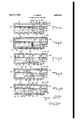
- Fig. 1 is a schematic vertical longitudinal section through that portion of a glass furnace that includes a new settling chamber.
- Fig. 2 is a similar section through a furnace employing a single melting-iining compartment ln combination with the new settling compartment.
- Fig. 3 is a similar section through a furnace having a separate ning compartment in which heating is accomplished by a combination of flame and electricity.
- Fig. 4 is illustrative, by a similar section, of a furnace having advanced control of glass currents.
- Fig. 5 is a similar section through a furnace of further modied form.
- the numeral I indicates the tank in which the operations of melting, iining, settling, and working occur.
- the numeral II shows the dome of the furnace. It is to be presumed that this furnace is constructed in a normal manner so far as the materials of its construction are concerned. At one end of this furnace is a melting zone I2, a filling zone I3 and a port for the admittance of materials I4. Heating is accomplished in this instance by resistors I which are submerged in the glass at a level related to that of an orifice is provided in a tame n that extends across the furnace and separates the two zones I2, I3 from the settling pool that is established between the baffle I'I and the baille I8.
- the orifice I6 which l gives admittance to the fined glass from the ning pool is nearthe top of the settling pool in the form of Fig. l, but the orifice I6 is completely submerged.
- the baille I8 has an orifice I9 that is near the bottom of the settling pool 20.
- the working compartment 2l has a kind of narrow passage or flue 22 through which the glass passing orifice I9 makes its way into the pool 23 from which the glass is withdrawn for shaping.
- This flue may be used if desired to cool, Still further, the glass from the temperature at which it passes through orifice I9. It is advantageous generally speaking to vconstruct and arrange the walls of the compartment containing pool 20 in such manner that in any one horizontal plane the four walls of the compartment exercise a like cooling effect upon the glass.
- the wall I'I is between the very hot glass of the fining compartment and the cooler glass of the settling compartment, which would tend to make this wall hotter than the other walls of the settling chamber.
- This problem has been solved by the conceptions of Fig. 2.
- the construction of the furnace is similar to Fig. l except that the wall I'I that separates the melting-lining compartment from the settling compartment extends upwardly from the bottom of the furnace to a position just below the level of the glass, so that a shallow vchannel exists between the iining and settling compartments through which the glass passes from the top of the one to the top of the other at the rate provided by the withdrawal of the glass through the discharge port 24.
- the three electrodes Ia, I5b, I5c are so arranged, across the meltingning compartment, that they constitute a barnier to the passage of unmelted particles and of unfined glass toward the channel above wall Il'.
- the very hot ned glass moving from the vicinity of electrode I5c passes over the wall I 'l' to the top of the settling chamber and slowly sinks as it cools through the chamber until it passes through the orifice I9 into the flue 22.
- FIG. 2 another diierence appears in that wall I'I' is hollow and is provided on the side of the lning chamber with heat insulation 25 and on the side of the setting chamber with a water jacket 26 through which cooling water at selected temperature may be passed in order to prevent the glass in the settling chamber', in the vicinity of the wall, from being kept at too high a temperature to serve satifactorily in the working chamber.
- isolate the fining chamber from the melting chamber to the left and the settling chamber to the right.
- two electrodes 32, 33 which maybe of Joule effect type if desired.
- These electrodes are suiilciently spaced from the walls of the furnace so that the relatively cool unned glass coming from the compartment I2 over the wall 30 tends because of increasing density as it cools to sink to the bottom of the compartment, whereas the hot currents rise about and particularly toward the right side of the electrodes attaining a very high temperature as they ascend and ridding themselves of the major portion of their occluded gases which leave the surface of the very fluid glass in bubbles.
- the superimposed relation of the electrodes tends to produce a superheating of the process which is quite beneficial at this stage.
- This very hot glass passes over the barrier 3
- the glass cools and the tine bubbles that were not liberated inthe fining chamber are dissolved in the glass, providing a glass at the entrance to the working chamber that is bubble-free.
- the arrows indicate the approximate path of the glass currents through the fining compartment.
- the heating of compartment I2 is by gas flame burners 34.
- the surface o! the glass in the flning chamber is also heated by a lia-me burner 35.
- the tank is provided with a depending barrier 40 and an upwardly projecting barrier 4I.
- the depending barrier terminates short of the bottom of the furnace so that a passage exists through which glass from the melting chamber may pass to the iining chamber.
- electrodes 42 operating by Joule eil'ect which project vertically through the bottom into and beneath the surface of the glass in the ilning chamber. These electrodes initiate currents of very hot glass that ascend toward the top of the lining chamber, are prevented from returning to the melting chamber by the baille 40, and flow over the top of the submerged barier 4I into the settling chamber 20.
- the arrows indicate the general course of the glass flow through the several chambers, and it will be observed from the arrangement and construction of these chambers that there will be a marked reduction in the iiow of uncontrolled convection currents throughout the furnace.
- the melting chamber l2 is separated from the ning chamber by means of a baille 43 which projects upward from the bottom of the tank and has a shallow channel through which the glass from the melting compartment may flow to the top of the lining compartment.
- a depending bave 44 projects downwardly from above the level of the glass in the flning chamber to a position toward the bottom thereof.
- electrodes 45 operating by Joule effect which subject the glass in the iining compartment to high temperature. The currents from these electrodes ascend into the space between barangs 43 and 44 so that the glass between those baffles is subjected to a continuous working by high temperature convection currents.
- the glass is withdrawn from the fining compartment beneath the baille 44 and enters a kind of flue 46 provided between baille 44 and a baiiie 41 projecting upwardly from the bottom of the furnace to a position beneath the level of the glass.
- Ihe fined glass taken from the flning compartment passes through the ue 46 and over the baffle 41 to the top of the settling chamber 20 wherein it is progressively cooled as it settles and absorbs tiny bubbles that did not escape during the previous steps of the process.
- the glass which is admitted to the compartment 20 is taken directly from the surface of the ning compartment, that is, from the level where the largest gas bubbles escape and from which the cooling and the absorption of little bubbles should commence.
- the major part, if not the entirety of the cooling from the temperature of flning is eilectuated in the conditioning chamber, under conditions of stability conducive to the attainment of a superior result.
- furnaces such as those represented in Figs. 3, 4, and 5 in which the heating is made simultaneously by name burners and by electric current in the mass of glass lend themselves particularly well to the accomplishment of the process, which lies in accomplishing by heating means exterior to the glass such as by flame burners a heating which is simply adapted to attain as well in the compartment of fusion as in that of fining a relatively low temperature in the neighborhood of the temperature of conditioning, while there is established in the flning compartment within the body of the mass of glass, by the passage of electric current, the higher temperature necessary to complete the fusion and to obtain the lning.
- auxiliary heating means such as flame burners, radiant heaters and electric current in the glass to assist in regularizing the attainment of a good glass temperature.
- heating means may be added to the compartment 23 to produce certain local effects used in different types of glass manufacture.
- the invention contemplates:
- the glass passes from the fining compartment to the conditioning compartment by a channel which connects the two compartments in the upper part of the bath.
- the conditioning compartment is associated with a. fusion and fining compartment heated by the passage of an electric current introduced by horizontal electrodes localized in the upper part of the bath.
- the conditioning compartment is associated with a lining compartment which communicates with the compartment of fusion by a channel in the neighborhood of the surface of the bath and which is heated by the passage of an electric current introduced by horizontal electrodes some of which are situated above others above the depths and near the surface of the bath.
- the conditioning compartment is associated with a nning compartment which communicates with the fusion compartment through the lower part of the bath and which is heated by the passage of the electric current introduced by vertical electrodes passing through the bottom of the compartment into contact with the lower part of the bath.
- the conditioning' compartment is associated with a lining compartment which communicates with the fusion compartment through the upper part of the bath and which is heated by the psage of electric current introduced by electrodes vertically localized in the lower part of the bath, a transverse wall being provided in the lining compartment on the side from which the glass discharges, to constitute a kind of vertical conduit taking the glass from the lower part of the ning compartment to lead it to the upper part of a conditioning compartment.
- the process of glassmaking that includes the steps of establishing separated ning, settling, and working pools of molten glass having a common surface level, electrically heating substantially the entire width of the upper level of the glass in the ning pool, said ning pool discharging from its upper level horizontally to the upper level of the settling pool, said settling pool discharging from its lower level, with a change of direction, substantially vertically to the working pool.
- a glass furnace including a chamber in which occurs the ning of glass and comprising electrical means for the heating of the glass bath, a separate settling chamber connected to the said chamber by a passage extending from the upper level of the glass in the ning chamber into the upper level of the glass in the settling chamber, and a separate working chamber connected to the settling chamber through a vertical passage issuing from the lower part of the settling chamber, the structural relationship of the chambers and passages comprising means to provide a. common glass surface level throughout the furnace.
Landscapes
- Chemical & Material Sciences (AREA)
- Engineering & Computer Science (AREA)
- Materials Engineering (AREA)
- Organic Chemistry (AREA)
- Surface Treatment Of Glass (AREA)
- Glass Melting And Manufacturing (AREA)
Description
June 27, 1950 P. ARBEIT 2,512,761
- ELECTRIC Guss FURNACE Patented vJune 27, 1950 ELECTRIC GLASS FUBNACE Pierre Arbeit, Paris, France, assigner to Societe Anonyme des Manufactures des Glaces et Prcduits Chimiques de Saint-Gobain, Chauny Cirey, Paris, France Application August 5, 1947, serial Nu. 766,277
In France January 16, 1946 Section 1, Public Law 690, August 8, 1946 Patent expires January A16, 1966 1o claims.' (01.13-6) This invention relates to glass making and has particular relation to improvements in the manufacture of glass by a continuous process in which the glass undergoes in sequence the melting of the raw materials, the fining of the melt, and the cooling of the very hot lined glass to a temperature suitable for working. A particularly valuable phase of the invention is related to glass furnaces of electric type wherein heating current three zones roughly corresponding to the three said phases of manufacture. Frequently, some l of the zones are combined, but in the more modern furnaces barriers have been erected in an attempt to isolate the three steps of the process. Nevertheless, it has been diicult to control the temperature at which the glass is received in the working zone or to insure the dissolving of small glass bubbles that do not escape from the fined glass before the solidication of the glass in the form of an object. Y
The operation of cooling, also called conditioning, has as an object to bring the glass from thevery high fining temperature at which it is very uid to a lower working temperature at which the glass may be conveniently employed in the fashioning of objects. It also has as an object to dissolve the small gas bubbles that have not escaped during iining. It has been desirable that the machines which shape the glass articles should be fed by glass at uniform temperature. However, heretofore these conditions have not been attained perfectly or continuously, and whenA attained at all, have been attained only imperfectly or with very great difllculty and by the use of compartments of large size and at the cost of maintaining, at high temperature, larger bodies of glass than are needed for the normal operation of the machines. The absorption of bubbles has been attained only by keeping the glass in the lining tank for a long period of time so that the convection currents will eventually lead to the homogenizatlon of the glass and the absorption of the bubbles.
It is an object of this invention to produce more homogeneous glass.
. Another object is to provide for the absorption and solution of small bubbles into fined glass so as to produce a bubble-free product.
Another object is to eliminate or materially reduce wandering glass currents.
Another object is to employ the convection currents arising from differences in temperature in the glass in combination with new furnace structure to attain useful ends, for instance to facilitate the transfer of glass from step to step of the process.
Another object is to reduce the size of the chambers in a glass furnace. v
Another object is to reduce the cost of heating by reducing the masses of the glass subjected to heating and by reducing the time of heating.
Another object is to employ electrical heating by submerged electrodes to facilitate the other objects of the invention and to acquire a new and more perfect continuous process of making glass.
The objects of the invention are accomplished, generally speaking, by a process that includes forming a ning pool of molten glass, fining the glass in the lining pool, withdrawing fined glass from the ning pool to the upper part of a. settling pool, allowing the withdrawn glass to settle and cool in the settling pool until gas bubbles have been absorbed and the temperature of the glass is right for working, and withdrawing glass from the settling pool to a Working pool. The new furnace involves a chamber in which the iining of the glass occurs, a working chamber, and between them a separate settling chamber that is connected to the fining chamber by a passage at the upper part of the settling chamber, and to the working chamber by a passage at the lower part of the settling chamber.
Under such conditions it has been proved thatv the cooling of the glass is uniformly effectuated without the need of giving large dimensions to the compartment, and this permits in consequence to obtain a cooling that is both uniform and quick.
This result might be explained by the fact that the glass, when it is cooled, tends to descend and consequently tends of itself both to withdraw from the orifice of entry and to approach the orifice of discharge from the compartment, but it does not reach the orifice of discharge except as it becomes sufficiently cool and at the same temperature as the glass which has already gathered before this orifice. Iniother words, the process tends togive automatically to the due to convection, movements which are produced in the usual installations and which are otherwise indispensable for the making of lhomogeneous glass by a kind of working, but which are naturally diiiicult to control. There is no longer danger that there will be set up across the conditioning zone currents of hotter glass capable of establishing diierences in temperature in the glass that issues, as is the case in prior art installations where, as is known, the glass enters the lower part and issues from the upper part. Furthermore, there is no ylonger danger that cool glass, having traversed the whole conditioning zone and having arrived at a proper temperature before the outlet orifice, will return into the ning zone because that would require the cold glass to rise in the conditioning compartment and repass the orifice by which it entered the compartment. There is thus prevented a movement of the glass which would have for its consequence to increase the quantity of glass that passes from the fining compartment into that of conditioning and to require of the latter to cool more glass than is necessary to feed the manufacturing machines. It should be understood that in practice the conditioning compartment conforming to the invention might be associated with auxiliary compartments interposed between that compartment and the compartment which precedes it and the compartment which follows it; that is to say, the lining compartment and the one from which the glass is withdrawn. Such auxiliary compartments might be necessary in eiect in order to associate the conditioning compartment contemplated by the invention with the different types of ning compartments or of working compartments. The essential is that, after ning, the cooling of the glass should take place in larger part in a compartment designed in conformity with the principles of the invention. Different ways of accomplishing the invention are given hereafter by way of non-limitative examples, reference being had to the attached drawings which represent:
Fig. 1 is a schematic vertical longitudinal section through that portion of a glass furnace that includes a new settling chamber.
Fig. 2 is a similar section through a furnace employing a single melting-iining compartment ln combination with the new settling compartment.
Fig. 3 is a similar section through a furnace having a separate ning compartment in which heating is accomplished by a combination of flame and electricity.
Fig. 4 is illustrative, by a similar section, of a furnace having advanced control of glass currents.
Fig. 5 is a similar section through a furnace of further modied form.
In the furnace illustrated in Fig. 1 the numeral I indicates the tank in which the operations of melting, iining, settling, and working occur. The numeral II shows the dome of the furnace. It is to be presumed that this furnace is constructed in a normal manner so far as the materials of its construction are concerned. At one end of this furnace is a melting zone I2, a filling zone I3 and a port for the admittance of materials I4. Heating is accomplished in this instance by resistors I which are submerged in the glass at a level related to that of an orifice is provided in a tame n that extends across the furnace and separates the two zones I2, I3 from the settling pool that is established between the baffle I'I and the baille I8. The orifice I6 which l gives admittance to the fined glass from the ning pool is nearthe top of the settling pool in the form of Fig. l, but the orifice I6 is completely submerged. The baille I8 has an orifice I9 that is near the bottom of the settling pool 20. Thus the hot fined glass enters at the top of the settling pool and is cooled as it sinks in the pool until it approaches an ideal working temperature as it passes through the orifice I9. The working compartment 2l has a kind of narrow passage or flue 22 through which the glass passing orifice I9 makes its way into the pool 23 from which the glass is withdrawn for shaping. This flue may be used if desired to cool, Still further, the glass from the temperature at which it passes through orifice I9. It is advantageous generally speaking to vconstruct and arrange the walls of the compartment containing pool 20 in such manner that in any one horizontal plane the four walls of the compartment exercise a like cooling effect upon the glass.
It is particularly to be noted, and this forms a part of the present invention, that the wall I'I is between the very hot glass of the fining compartment and the cooler glass of the settling compartment, which would tend to make this wall hotter than the other walls of the settling chamber. This problem has been solved by the conceptions of Fig. 2. In that figure the construction of the furnace is similar to Fig. l except that the wall I'I that separates the melting-lining compartment from the settling compartment extends upwardly from the bottom of the furnace to a position just below the level of the glass, so that a shallow vchannel exists between the iining and settling compartments through which the glass passes from the top of the one to the top of the other at the rate provided by the withdrawal of the glass through the discharge port 24. The three electrodes Ia, I5b, I5c are so arranged, across the meltingning compartment, that they constitute a barnier to the passage of unmelted particles and of unfined glass toward the channel above wall Il'. The very hot ned glass moving from the vicinity of electrode I5c passes over the wall I 'l' to the top of the settling chamber and slowly sinks as it cools through the chamber until it passes through the orifice I9 into the flue 22.
In Fig. 2 another diierence appears in that wall I'I' is hollow and is provided on the side of the lning chamber with heat insulation 25 and on the side of the setting chamber with a water jacket 26 through which cooling water at selected temperature may be passed in order to prevent the glass in the settling chamber', in the vicinity of the wall, from being kept at too high a temperature to serve satifactorily in the working chamber.
In the structure of Fig. 3 two walls 30, 3| isolate the fining chamber from the melting chamber to the left and the settling chamber to the right. Between these two walls are located two electrodes 32, 33 which maybe of Joule effect type if desired. These electrodes are suiilciently spaced from the walls of the furnace so that the relatively cool unned glass coming from the compartment I2 over the wall 30 tends because of increasing density as it cools to sink to the bottom of the compartment, whereas the hot currents rise about and particularly toward the right side of the electrodes attaining a very high temperature as they ascend and ridding themselves of the major portion of their occluded gases which leave the surface of the very fluid glass in bubbles. The superimposed relation of the electrodes, which may be as many in number as desired, tends to produce a superheating of the process which is quite beneficial at this stage. This very hot glass passes over the barrier 3| at the rate provided by the withdrawal of glass through the port 24 to the top of the settling chamber in which it descends at the rate provided by the size oi the chamber and the rate of withdrawal through port 24 until it reaches the bottom. During its settling and passage through the settling chamber, the glass cools and the tine bubbles that were not liberated inthe fining chamber are dissolved in the glass, providing a glass at the entrance to the working chamber that is bubble-free. The arrows indicate the approximate path of the glass currents through the fining compartment. In this form of the invention the heating of compartment I2 is by gas flame burners 34. In addition, the surface o! the glass in the flning chamber is also heated by a lia-me burner 35.
In the structure described in Fig. 4 the tank is provided with a depending barrier 40 and an upwardly projecting barrier 4I. The depending barrier terminates short of the bottom of the furnace so that a passage exists through which glass from the melting chamber may pass to the iining chamber. With the lining chamber are electrodes 42 operating by Joule eil'ect which project vertically through the bottom into and beneath the surface of the glass in the ilning chamber. These electrodes initiate currents of very hot glass that ascend toward the top of the lining chamber, are prevented from returning to the melting chamber by the baille 40, and flow over the top of the submerged baiile 4I into the settling chamber 20. The arrows indicate the general course of the glass flow through the several chambers, and it will be observed from the arrangement and construction of these chambers that there will be a marked reduction in the iiow of uncontrolled convection currents throughout the furnace.
In Fig. 5 the melting chamber l2 is separated from the ning chamber by means of a baille 43 which projects upward from the bottom of the tank and has a shallow channel through which the glass from the melting compartment may flow to the top of the lining compartment. A depending baiile 44 projects downwardly from above the level of the glass in the flning chamber to a position toward the bottom thereof. Between these two baflies are located electrodes 45 operating by Joule effect which subject the glass in the iining compartment to high temperature. The currents from these electrodes ascend into the space between baiiles 43 and 44 so that the glass between those baffles is subjected to a continuous working by high temperature convection currents. The glass is withdrawn from the fining compartment beneath the baille 44 and enters a kind of flue 46 provided between baille 44 and a baiiie 41 projecting upwardly from the bottom of the furnace to a position beneath the level of the glass. Ihe fined glass taken from the flning compartment passes through the ue 46 and over the baffle 41 to the top of the settling chamber 20 wherein it is progressively cooled as it settles and absorbs tiny bubbles that did not escape during the previous steps of the process.
It is generally to be noted that the glass which is admitted to the compartment 20 is taken directly from the surface of the ning compartment, that is, from the level where the largest gas bubbles escape and from which the cooling and the absorption of little bubbles should commence. In other terms, the major part, if not the entirety of the cooling from the temperature of flning is eilectuated in the conditioning chamber, under conditions of stability conducive to the attainment of a superior result.
It is to be noted that the types of furnace such as those represented in Figs. 3, 4, and 5 in which the heating is made simultaneously by name burners and by electric current in the mass of glass lend themselves particularly well to the accomplishment of the process, which lies in accomplishing by heating means exterior to the glass such as by flame burners a heating which is simply adapted to attain as well in the compartment of fusion as in that of fining a relatively low temperature in the neighborhood of the temperature of conditioning, while there is established in the flning compartment within the body of the mass of glass, by the passage of electric current, the higher temperature necessary to complete the fusion and to obtain the lning.
It should be understood that it is not excluded from the spirit of the invention to employ in the conditioning compartment auxiliary heating means such as flame burners, radiant heaters and electric current in the glass to assist in regularizing the attainment of a good glass temperature. Similarly, heating means may be added to the compartment 23 to produce certain local effects used in different types of glass manufacture.
The invention contemplates:
l. A continuous process for making glass in accordance with which glass is made to pass successively through different compartments where fusion, flning, conditioning, or cooling are accomplished, the process lying in conditioning the glass in a compartment in which the glass at high temperature which issues from the ilning compartment enters the upper part and issues from the lower part.
2. Furnaces for the accomplishment of the process following (1) characterized by the following points taken separately or in combination:
a. The glass passes from the fining compartment to the conditioning compartment by a channel which connects the two compartments in the upper part of the bath.
b.' After conditioning the glass enters the compartment of withdrawal through a vertical conduit of small section, which it enters from the lower part of the conditioning compartment.
vc. The conditioning compartment is associated with a. fusion and fining compartment heated by the passage of an electric current introduced by horizontal electrodes localized in the upper part of the bath.
d. The conditioning compartment is associated with a lining compartment which communicates with the compartment of fusion by a channel in the neighborhood of the surface of the bath and which is heated by the passage of an electric current introduced by horizontal electrodes some of which are situated above others above the depths and near the surface of the bath.
e. The conditioning compartment is associated with a nning compartment which communicates with the fusion compartment through the lower part of the bath and which is heated by the passage of the electric current introduced by vertical electrodes passing through the bottom of the compartment into contact with the lower part of the bath.
f. The conditioning' compartment is associated with a lining compartment which communicates with the fusion compartment through the upper part of the bath and which is heated by the psage of electric current introduced by electrodes vertically localized in the lower part of the bath, a transverse wall being provided in the lining compartment on the side from which the glass discharges, to constitute a kind of vertical conduit taking the glass from the lower part of the ning compartment to lead it to the upper part of a conditioning compartment.
As many apparently widely different embodiments of the present invention may be made without departing from the spirit and scope thereof, it is to be understood that the invention is not limited to the speciiic embodiments, except as dened in the appended claims.
What is claimed is:
1. The process of glassmaking that includes the steps of establishing separated ning, settling, and working pools of molten glass having a common surface level, electrically heating substantially the entire width of the upper level of the glass in the ning pool, said ning pool discharging from its upper level horizontally to the upper level of the settling pool, said settling pool discharging from its lower level, with a change of direction, substantially vertically to the working pool.
2. The process according to claim 1 in which the glass discharged to the settling pool is taken from beneath the surface oi' the ning pool.
3. The process according to claim 1 in which the glass discharged to the settling pool is taken from the surface of the ning pool.
4. The process according to claim 1 in which a stream of glass is taken from the bottom of the nning pool, moved vertically, and discharged horizontally to the top of the settling pool.
5. A glass furnace including a chamber in which occurs the ning of glass and comprising electrical means for the heating of the glass bath, a separate settling chamber connected to the said chamber by a passage extending from the upper level of the glass in the ning chamber into the upper level of the glass in the settling chamber, and a separate working chamber connected to the settling chamber through a vertical passage issuing from the lower part of the settling chamber, the structural relationship of the chambers and passages comprising means to provide a. common glass surface level throughout the furnace.
6. The furnace of claim 5 in which the upper passage is wholly submerged.
7. The furnace of claim 5 in which the upper passage is open.
8. The furnace of claim 5 in which the settling chamber is separated from the upstream zones by a wall arising from the bottom almost to the surface of the glass, and a dipping bridge wall extends therebefore from above the surface almost to the bottom, whereby ned glass passes horizontally beneath the bridge wall, vertically between the walls. and is horizontally discharged over the settling chamber wall to the top of the settling chamber.
9. The furnace of claim 5 in which at least a submerged electrode in the upper part ci the nning chamber acts as a barrier to the travel of unned glass toward the passage opening into the settling chamber.
10. The furnace of claim 5 in which the ning chamber is electrically heated by means of submerged vertical electrodes penetrating through its bottom wall.
PmRE ARBEIT.
REFERENCES CNED The following references are of record in the ile of this patent:
UNITED STATES PATENTS Number Name Date Re. 12,323 Richardson Feb. 28, 1905 248,109 Fetters Aug. 23, 1881 972,778 Sauvageon Oct. 11, 1910 1,552,555 Gravel Sept. 8, 1925 4@ 1,593,054 Arbeit July 20, 1926 1,611,328 Arbogast Dec. 21, 1926 1,656,510 Cornelius Jan. 17, 1928 1,820,248 Raeder Aug. 25, 1931 1,880,541 Wadman Oct. 4, 1932 1,905,534 Wadman Apr. 25, 1933 1,944,855 Wadman Jan. 23, 1934 2,068,925 Mulholland Jan. 26, 1937 2,277,678 Borel Mar. 31, 1942 2,283,188 Cornelius May 19, 1942 2,283,800 Ferguson May 19, 1942 2,397,852 Gentil Apr. 2, 1946 2,413,037 De Voe Dec. 24, 1946 FOREIGN PATENTS Number Country Date 250,536 Great Britain July 29, 1926 Certiicate of Correction Patent No. 2,512,761 June 27, 1950 PIERRE ARBEIT It is hereby certied that error appears in the printed specification of the above numbered patent requiring correction as follows:
Column 5, line 33, for the Word With read Within;
and that the said Letters Patent should be read With this correction therein that the seme may conform to the record of the case in the Patent Ooe.
Signed and sealed this 19th dey of September, A. D. 1950.
[SEAL] A THOMAS F. MURPHY,
Assistant O'ommz'ssone?A of Patents.
Certificate of Correction 'Patent No. 2,512,761 June 27, 195ok PIERRE ARBEIT It is hereby certified that error appears in the printed specification of the above numbered patent requiring correction as follows:
Column 5, line 33, for the Word With read Within;
and that the said Letters Patent should be read with this correction therein that the same may conform to the record of the case in the Patent Oce.
Signed and sealed this 19th day of September, A. D. 1950.
[SEAL] THOMAS F. MURPHY,
Assistant Commissioner of Patents.
Applications Claiming Priority (1)
| Application Number | Priority Date | Filing Date | Title |
|---|---|---|---|
| FR999843T | 1946-01-16 |
Publications (1)
| Publication Number | Publication Date |
|---|---|
| US2512761A true US2512761A (en) | 1950-06-27 |
Family
ID=9559960
Family Applications (1)
| Application Number | Title | Priority Date | Filing Date |
|---|---|---|---|
| US766277A Expired - Lifetime US2512761A (en) | 1946-01-16 | 1947-08-05 | Electric glass furnace |
Country Status (4)
| Country | Link |
|---|---|
| US (1) | US2512761A (en) |
| BE (1) | BE470589A (en) |
| FR (1) | FR999843A (en) |
| GB (1) | GB620355A (en) |
Cited By (26)
| Publication number | Priority date | Publication date | Assignee | Title |
|---|---|---|---|---|
| US2610217A (en) * | 1949-03-15 | 1952-09-09 | Ferro Corp | Electric enamel furnace |
| US2686820A (en) * | 1950-07-04 | 1954-08-17 | Saint Gobain | Glass furnace and process for melting glass |
| US2780891A (en) * | 1950-05-17 | 1957-02-12 | Saint Gobain | Apparatus for melting glass |
| US2866838A (en) * | 1956-02-16 | 1958-12-30 | Stratabar Process Company | Method and apparatus for producing molten silicates |
| US2902524A (en) * | 1955-10-26 | 1959-09-01 | Stratabar Process Company | Method and apparatus for producing molten silicates |
| US2990438A (en) * | 1945-07-07 | 1961-06-27 | Saint Gobain | Methods of and tank furnaces for making glass |
| US3108149A (en) * | 1959-11-18 | 1963-10-22 | Libbey Owens Ford Glass Co | Method and apparatus for glass melting |
| US3160692A (en) * | 1960-08-01 | 1964-12-08 | Warren H F Schmieding | Apparatus for controlling the flow of molten silicates through throat type continuous melting furnaces |
| US3208841A (en) * | 1960-10-06 | 1965-09-28 | Owens Illinois Glass Co | Apparatus for melting glass |
| US3218144A (en) * | 1961-06-21 | 1965-11-16 | Saint Gobain | Glass tank furnaces with submerged heating and cooling means |
| US3400204A (en) * | 1964-02-29 | 1968-09-03 | Element Ltd | Method of melting and supplying glass along a feeder duct |
| US4012218A (en) * | 1975-11-13 | 1977-03-15 | Helmut Sorg | Method and apparatus for melting glass |
| US4752938A (en) * | 1984-04-12 | 1988-06-21 | Corning Glass Works | Baffled glass melting furnaces |
| FR2614614A1 (en) * | 1987-04-30 | 1988-11-04 | Glaverbel | METHOD AND BASIN OVEN FOR THE MANUFACTURE OF GLASS |
| US4831633A (en) * | 1988-06-01 | 1989-05-16 | King, Taudevin & Gregson (Holdings) Limited | Glass melting furnace |
| US4961772A (en) * | 1988-09-20 | 1990-10-09 | Toledo Engineering Co., Inc. | Method and apparatus for continuously melting glass and intermittently withdrawing melted glass |
| EP0410338A1 (en) * | 1989-07-27 | 1991-01-30 | Friedrich Dipl.-Ing. Müller | Melting vessel for the preparation of glass |
| US5588978A (en) * | 1992-11-24 | 1996-12-31 | Imtec | Process and apparatus for coloring glass |
| US5925165A (en) * | 1994-09-29 | 1999-07-20 | Von Roll Umwelttechnik Ag | Process and apparatus for the 3-stage treatment of solid residues from refuse incineration plants |
| US20040099009A1 (en) * | 2002-08-09 | 2004-05-27 | Wilfried Linz | Method for refining a glass melt and an apparatus for melting and refining a glass melt |
| WO2015164694A1 (en) * | 2014-04-25 | 2015-10-29 | Owens-Brockway Glass Container Inc. | Glass furnace |
| US9776904B2 (en) | 2014-06-06 | 2017-10-03 | Owens-Brockway Glass Container Inc. | Process and apparatus for refining molten glass |
| CN107586006A (en) * | 2017-08-29 | 2018-01-16 | 东旭科技集团有限公司 | The glass obtained after the processing method of low-temperature polysilicon silica glass and its processing and application |
| US11427492B2 (en) | 2019-07-11 | 2022-08-30 | Owens-Brockway Glass Container Inc. | Multi-chamber submerged combustion melter and system |
| EP4186872A1 (en) * | 2021-11-30 | 2023-05-31 | Saint-Gobain Glass France | Hydride furnace for manufacturing glass with three convection belts for powering a flotation unit |
| WO2023099245A1 (en) * | 2021-11-30 | 2023-06-08 | Saint-Gobain Glass France | Hybrid glass-manufacturing furnace with three convection currents for feeding a float unit |
Citations (17)
| Publication number | Priority date | Publication date | Assignee | Title |
|---|---|---|---|---|
| US246109A (en) * | 1881-08-23 | Furnace for melting and blowing glass | ||
| US972778A (en) * | 1909-08-05 | 1910-10-11 | Marius Sauvageon | Electric furnace for the continuous manufacture of glass. |
| US1552555A (en) * | 1923-01-20 | 1925-09-08 | Frederick Charles Hoar | Glass-refining furnace |
| US1593054A (en) * | 1923-12-06 | 1926-07-20 | Saint Gobain | Furnace for glass manufacture |
| GB250536A (en) * | 1925-04-10 | 1926-07-29 | Saint Gobain | An improved process and apparatus for fining glass |
| US1611328A (en) * | 1924-12-01 | 1926-12-21 | John I Arbogast | Method and apparatus for manufacturing glass |
| US1656510A (en) * | 1925-03-23 | 1928-01-17 | Cornelius Cornelius Erik | Electric furnace for melting or producing glass, water-glass, cement, or other substances |
| US1820248A (en) * | 1928-05-19 | 1931-08-25 | Hartford Empire Co | Glass making furnace and method |
| US1880541A (en) * | 1930-10-21 | 1932-10-04 | Hartford Empire Co | Process and apparatus for making glass |
| US1905534A (en) * | 1931-07-25 | 1933-04-25 | Hartford Empire Co | Apparatus for and method of making glass |
| US1944855A (en) * | 1932-07-28 | 1934-01-23 | Hartford Empire Co | Method of and apparatus for making glass |
| US2068925A (en) * | 1934-06-13 | 1937-01-26 | Hartford Empire Co | Glass making apparatus and method |
| US2277678A (en) * | 1937-08-10 | 1942-03-31 | Saint Gobain | Electric furnace for melting glass |
| US2283800A (en) * | 1941-05-14 | 1942-05-19 | Ferguson John | Electrode arrangement for glass furnaces or the like |
| US2283188A (en) * | 1941-01-06 | 1942-05-19 | Hartford Empire Co | Electric furnace |
| US2397852A (en) * | 1944-12-23 | 1946-04-02 | Saint Gobain | Glassmaking furnace |
| US2413037A (en) * | 1943-09-18 | 1946-12-24 | Corning Glass Works | Electric glass melting furnace |
-
0
- BE BE470589D patent/BE470589A/xx unknown
-
1946
- 1946-01-16 FR FR999843D patent/FR999843A/en not_active Expired
-
1947
- 1947-01-15 GB GB1366/47A patent/GB620355A/en not_active Expired
- 1947-08-05 US US766277A patent/US2512761A/en not_active Expired - Lifetime
Patent Citations (17)
| Publication number | Priority date | Publication date | Assignee | Title |
|---|---|---|---|---|
| US246109A (en) * | 1881-08-23 | Furnace for melting and blowing glass | ||
| US972778A (en) * | 1909-08-05 | 1910-10-11 | Marius Sauvageon | Electric furnace for the continuous manufacture of glass. |
| US1552555A (en) * | 1923-01-20 | 1925-09-08 | Frederick Charles Hoar | Glass-refining furnace |
| US1593054A (en) * | 1923-12-06 | 1926-07-20 | Saint Gobain | Furnace for glass manufacture |
| US1611328A (en) * | 1924-12-01 | 1926-12-21 | John I Arbogast | Method and apparatus for manufacturing glass |
| US1656510A (en) * | 1925-03-23 | 1928-01-17 | Cornelius Cornelius Erik | Electric furnace for melting or producing glass, water-glass, cement, or other substances |
| GB250536A (en) * | 1925-04-10 | 1926-07-29 | Saint Gobain | An improved process and apparatus for fining glass |
| US1820248A (en) * | 1928-05-19 | 1931-08-25 | Hartford Empire Co | Glass making furnace and method |
| US1880541A (en) * | 1930-10-21 | 1932-10-04 | Hartford Empire Co | Process and apparatus for making glass |
| US1905534A (en) * | 1931-07-25 | 1933-04-25 | Hartford Empire Co | Apparatus for and method of making glass |
| US1944855A (en) * | 1932-07-28 | 1934-01-23 | Hartford Empire Co | Method of and apparatus for making glass |
| US2068925A (en) * | 1934-06-13 | 1937-01-26 | Hartford Empire Co | Glass making apparatus and method |
| US2277678A (en) * | 1937-08-10 | 1942-03-31 | Saint Gobain | Electric furnace for melting glass |
| US2283188A (en) * | 1941-01-06 | 1942-05-19 | Hartford Empire Co | Electric furnace |
| US2283800A (en) * | 1941-05-14 | 1942-05-19 | Ferguson John | Electrode arrangement for glass furnaces or the like |
| US2413037A (en) * | 1943-09-18 | 1946-12-24 | Corning Glass Works | Electric glass melting furnace |
| US2397852A (en) * | 1944-12-23 | 1946-04-02 | Saint Gobain | Glassmaking furnace |
Cited By (42)
| Publication number | Priority date | Publication date | Assignee | Title |
|---|---|---|---|---|
| US2990438A (en) * | 1945-07-07 | 1961-06-27 | Saint Gobain | Methods of and tank furnaces for making glass |
| US2610217A (en) * | 1949-03-15 | 1952-09-09 | Ferro Corp | Electric enamel furnace |
| US2780891A (en) * | 1950-05-17 | 1957-02-12 | Saint Gobain | Apparatus for melting glass |
| US2686820A (en) * | 1950-07-04 | 1954-08-17 | Saint Gobain | Glass furnace and process for melting glass |
| US2902524A (en) * | 1955-10-26 | 1959-09-01 | Stratabar Process Company | Method and apparatus for producing molten silicates |
| US2866838A (en) * | 1956-02-16 | 1958-12-30 | Stratabar Process Company | Method and apparatus for producing molten silicates |
| US3108149A (en) * | 1959-11-18 | 1963-10-22 | Libbey Owens Ford Glass Co | Method and apparatus for glass melting |
| US3160692A (en) * | 1960-08-01 | 1964-12-08 | Warren H F Schmieding | Apparatus for controlling the flow of molten silicates through throat type continuous melting furnaces |
| US3208841A (en) * | 1960-10-06 | 1965-09-28 | Owens Illinois Glass Co | Apparatus for melting glass |
| US3218144A (en) * | 1961-06-21 | 1965-11-16 | Saint Gobain | Glass tank furnaces with submerged heating and cooling means |
| US3400204A (en) * | 1964-02-29 | 1968-09-03 | Element Ltd | Method of melting and supplying glass along a feeder duct |
| US4012218A (en) * | 1975-11-13 | 1977-03-15 | Helmut Sorg | Method and apparatus for melting glass |
| US4752938A (en) * | 1984-04-12 | 1988-06-21 | Corning Glass Works | Baffled glass melting furnaces |
| BE1004158A3 (en) * | 1987-04-30 | 1992-10-06 | Glaverbel | Method and oven glass basin for manufacturing. |
| DE3814425A1 (en) * | 1987-04-30 | 1988-11-17 | Glaverbel | METHOD AND OVEN FOR PRODUCING GLASS |
| US4929266A (en) * | 1987-04-30 | 1990-05-29 | Glaverbel | Method of manufacturing glass |
| US5078777A (en) * | 1987-04-30 | 1992-01-07 | Glaverbel | Glass-melting furnace |
| FR2614614A1 (en) * | 1987-04-30 | 1988-11-04 | Glaverbel | METHOD AND BASIN OVEN FOR THE MANUFACTURE OF GLASS |
| DE3814425C2 (en) * | 1987-04-30 | 1998-04-09 | Glaverbel | Continuous glass melting tank furnace and method of making glass |
| US4831633A (en) * | 1988-06-01 | 1989-05-16 | King, Taudevin & Gregson (Holdings) Limited | Glass melting furnace |
| US4961772A (en) * | 1988-09-20 | 1990-10-09 | Toledo Engineering Co., Inc. | Method and apparatus for continuously melting glass and intermittently withdrawing melted glass |
| EP0410338A1 (en) * | 1989-07-27 | 1991-01-30 | Friedrich Dipl.-Ing. Müller | Melting vessel for the preparation of glass |
| US5588978A (en) * | 1992-11-24 | 1996-12-31 | Imtec | Process and apparatus for coloring glass |
| US5925165A (en) * | 1994-09-29 | 1999-07-20 | Von Roll Umwelttechnik Ag | Process and apparatus for the 3-stage treatment of solid residues from refuse incineration plants |
| US20040099009A1 (en) * | 2002-08-09 | 2004-05-27 | Wilfried Linz | Method for refining a glass melt and an apparatus for melting and refining a glass melt |
| US9822027B2 (en) | 2014-04-25 | 2017-11-21 | Owens-Brockway Glass Container Inc. | Glass furnace with bottom material feed |
| CN106458676B (en) * | 2014-04-25 | 2019-06-14 | 欧文斯-布洛克威玻璃容器有限公司 | Glass furnace |
| CN109455902B (en) * | 2014-04-25 | 2022-03-15 | 欧文斯-布洛克威玻璃容器有限公司 | Glass kiln |
| WO2015164694A1 (en) * | 2014-04-25 | 2015-10-29 | Owens-Brockway Glass Container Inc. | Glass furnace |
| CN106458676A (en) * | 2014-04-25 | 2017-02-22 | 欧文斯-布洛克威玻璃容器有限公司 | Glass furnace |
| US10029934B2 (en) | 2014-04-25 | 2018-07-24 | Owens-Brockway Glass Container Inc. | Glass furnace |
| US10118852B2 (en) | 2014-04-25 | 2018-11-06 | Owens-Brockway Glass Container Inc. | Glass furnace |
| CN109336364A (en) * | 2014-04-25 | 2019-02-15 | 欧文斯-布洛克威玻璃容器有限公司 | Glass furnace |
| CN109455902A (en) * | 2014-04-25 | 2019-03-12 | 欧文斯-布洛克威玻璃容器有限公司 | Glass furnace |
| US10807897B2 (en) | 2014-06-06 | 2020-10-20 | Owens-Brockway Glass Container Inc. | Process and apparatus for refining molten glass |
| US9776904B2 (en) | 2014-06-06 | 2017-10-03 | Owens-Brockway Glass Container Inc. | Process and apparatus for refining molten glass |
| CN107586006A (en) * | 2017-08-29 | 2018-01-16 | 东旭科技集团有限公司 | The glass obtained after the processing method of low-temperature polysilicon silica glass and its processing and application |
| CN107586006B (en) * | 2017-08-29 | 2021-03-23 | 东旭光电科技股份有限公司 | Processing method of low-temperature polycrystalline silicon glass, glass obtained after processing and application |
| US11427492B2 (en) | 2019-07-11 | 2022-08-30 | Owens-Brockway Glass Container Inc. | Multi-chamber submerged combustion melter and system |
| EP4186872A1 (en) * | 2021-11-30 | 2023-05-31 | Saint-Gobain Glass France | Hydride furnace for manufacturing glass with three convection belts for powering a flotation unit |
| EP4186871A1 (en) * | 2021-11-30 | 2023-05-31 | Saint-Gobain Glass France | Method and hydride furnace for manufacturing glass comprising three convection belts |
| WO2023099245A1 (en) * | 2021-11-30 | 2023-06-08 | Saint-Gobain Glass France | Hybrid glass-manufacturing furnace with three convection currents for feeding a float unit |
Also Published As
| Publication number | Publication date |
|---|---|
| BE470589A (en) | |
| FR999843A (en) | 1952-02-05 |
| GB620355A (en) | 1949-03-23 |
Similar Documents
| Publication | Publication Date | Title |
|---|---|---|
| US2512761A (en) | Electric glass furnace | |
| US3015190A (en) | Apparatus and method for circulating molten glass | |
| US3519412A (en) | Apparatus for melting and refining glass | |
| US3260587A (en) | Method of melting glass with submerged combustion heaters and apparatus therefor | |
| US2159361A (en) | Electric furnace | |
| US4929266A (en) | Method of manufacturing glass | |
| US3109045A (en) | Electrically heated glass melting unit | |
| US2122469A (en) | Apparatus for making glass | |
| US1953023A (en) | Method and apparatus for making glass | |
| US2773111A (en) | Method and apparatus for manufacturing glass | |
| US1880541A (en) | Process and apparatus for making glass | |
| CZ278070B6 (en) | Glass-melting furnace | |
| US2636914A (en) | Furnace for making glass | |
| US3429684A (en) | Glass melting furnace with vacuum feed means | |
| JP2001080921A (en) | Device and method for refining glass or ceramic | |
| US3305340A (en) | Method and apparatus for generating currents in molten glass | |
| US3583861A (en) | Method and apparatus for refining fusible material | |
| US2658095A (en) | Process and apparatus for making glass | |
| US2600490A (en) | Glass melting method | |
| US2203269A (en) | Method of and apparatus for making glass | |
| NO841378L (en) | furnace | |
| US3261677A (en) | Glass furnace having a refining chamber for the molten glass | |
| US2990438A (en) | Methods of and tank furnaces for making glass | |
| US1593054A (en) | Furnace for glass manufacture | |
| US2686820A (en) | Glass furnace and process for melting glass |