US2504796A - Adjustable-angle pivot-typerod joint - Google Patents
Adjustable-angle pivot-typerod joint Download PDFInfo
- Publication number
- US2504796A US2504796A US733895A US73389547A US2504796A US 2504796 A US2504796 A US 2504796A US 733895 A US733895 A US 733895A US 73389547 A US73389547 A US 73389547A US 2504796 A US2504796 A US 2504796A
- Authority
- US
- United States
- Prior art keywords
- shank
- joint
- adjustable
- typerod
- head
- Prior art date
- Legal status (The legal status is an assumption and is not a legal conclusion. Google has not performed a legal analysis and makes no representation as to the accuracy of the status listed.)
- Expired - Lifetime
Links
Images
Classifications
-
- B—PERFORMING OPERATIONS; TRANSPORTING
- B25—HAND TOOLS; PORTABLE POWER-DRIVEN TOOLS; MANIPULATORS
- B25G—HANDLES FOR HAND IMPLEMENTS
- B25G1/00—Handle constructions
- B25G1/06—Handle constructions reversible or adjustable for position
- B25G1/063—Handle constructions reversible or adjustable for position for screwdrivers, wrenches or spanners
-
- B—PERFORMING OPERATIONS; TRANSPORTING
- B25—HAND TOOLS; PORTABLE POWER-DRIVEN TOOLS; MANIPULATORS
- B25B—TOOLS OR BENCH DEVICES NOT OTHERWISE PROVIDED FOR, FOR FASTENING, CONNECTING, DISENGAGING OR HOLDING
- B25B23/00—Details of, or accessories for, spanners, wrenches, screwdrivers
- B25B23/0007—Connections or joints between tool parts
- B25B23/0021—Prolongations interposed between handle and tool
-
- B—PERFORMING OPERATIONS; TRANSPORTING
- B25—HAND TOOLS; PORTABLE POWER-DRIVEN TOOLS; MANIPULATORS
- B25B—TOOLS OR BENCH DEVICES NOT OTHERWISE PROVIDED FOR, FOR FASTENING, CONNECTING, DISENGAGING OR HOLDING
- B25B23/00—Details of, or accessories for, spanners, wrenches, screwdrivers
- B25B23/0007—Connections or joints between tool parts
- B25B23/0028—Angular adjustment means between tool head and handle
-
- Y—GENERAL TAGGING OF NEW TECHNOLOGICAL DEVELOPMENTS; GENERAL TAGGING OF CROSS-SECTIONAL TECHNOLOGIES SPANNING OVER SEVERAL SECTIONS OF THE IPC; TECHNICAL SUBJECTS COVERED BY FORMER USPC CROSS-REFERENCE ART COLLECTIONS [XRACs] AND DIGESTS
- Y10—TECHNICAL SUBJECTS COVERED BY FORMER USPC
- Y10T—TECHNICAL SUBJECTS COVERED BY FORMER US CLASSIFICATION
- Y10T403/00—Joints and connections
- Y10T403/32—Articulated members
- Y10T403/32254—Lockable at fixed position
- Y10T403/32262—At selected angle
- Y10T403/32319—At selected angle including pivot stud
- Y10T403/32327—At selected angle including pivot stud including radially spaced detent or latch component
- Y10T403/32336—Engaging notch or recess in outer periphery of component
Definitions
- This invention relates to tools and more particularly to those of the wrench type and especially those pertaining to shank extensions employed with same to manipulate bolts or nuts disposed in hard-of-access locations.
- .lmother object of the invention is to provide a new and improved wrench shank that will afford a strong form of holder for the replaceable socket heads used in connection therewith.
- a further object of the herein described invention is to provide a new and improved wrench that will permit the operating head used therewith to be readily manipulated for replacement and also to be held substantially in position when in use.
- Figure 1 is a side elevational view of a wrench shank embodying this invention
- Figure 2 is a plan view of Figure 1;
- Figure 3 is an end view of Figure 2.
- lll represents the shank extension of a wrench of conventional form.
- One end portionl I! is swaged out or enlarged and provided with a polygonal recess I2 into which the tongue of a preceding wrench shank (not shown) is inserted to operate it.
- the other end portion I 3 of the shank extension II! is also swaged out to form a bifurcated jaw internally arcuate and laterally open cn opposite sides to permit the insertions and rotation of an operable head I4 adaptable with a male end socket-engaging projection I5 for insertion in a socket to be rotated thereby.
- the head I4 has a rounded rib I'I straddled over its peripheral surface I8 and arranged to t at its back and sides into an arcuate groove I 8 provided in "the shank I D.
- Thehead i4 has two sides 2l)l A-iiat and tted close against the inner side surfaces 2
- a passage 22 runs transversely through the jaw sides and aligns with a passage 23 in the head I4 so that a pin 26 of cylindrical contour may be passed through both to hold them together as a unit.
- the projection I5 has a conventional ball lock 24 arranged to secure it to the socket of the extension that the projection may be attached to at the time. Likewise a ball lock 25 is provided in the recess I2 for a similar purpose.
- the removal of the head is readily performed by removing the pin 26 and withdrawing the operable head E4 from between sides 2l of the jaw I3.
- the rib Il which is preferably knurled, facilitates this operation, as it enables the head to be readily grasped between the fingers of the operator.
- the head may be rotated on the pin 26 through an arc as long as that of the rib I1 and at the same time be substantially held within the jaw I3. This jaw also distributes the stresses exerted on the head to the shank proper and relieves the sides 2
- a hinged joint comprising a shank having an enlarged end portion provided with a U-shaped slot forming spaced ears having confronting parallelsurfaces, said surfaces merging into a transverse-surface of said shank and forming the bot- Y torn of said U-shaped slot, said transverse surface being transverselyconcave, axially aligned pivot means provided in said ears, an arcuate transversely extending slot formed in said concave sur- .face, said arcuate slot and said concave surface having a curved peripheral surface complementary to the concave surface of said shank and to said-rib and arcuate slot being complementary in cross-sectional size to thereby prevent excessive torsional strain on said pivot means.
Landscapes
- Engineering & Computer Science (AREA)
- Mechanical Engineering (AREA)
- Details Of Spanners, Wrenches, And Screw Drivers And Accessories (AREA)
Description
April 18, 1950 R. D. BOYD ADJUSTABLE-ANGLE PIVOT-TYPE ROD JOINT l Filed March l1, 1947 Patented Apr. 18,' 1950 Nen;
v Amministra@ RGD J OIN'I Raymond Daley Boyd, vSan Antonio, Tex.
Application March 11, 1947, Serial No. 733,895
2 Claims.
This invention relates to tools and more particularly to those of the wrench type and especially those pertaining to shank extensions employed with same to manipulate bolts or nuts disposed in hard-of-access locations.
It is an obiect of the present invention to provide a new and improved wrench shank that will avoid one or more of the disadvantages and limitations of the prior art.
.lmother obiect of the invention is to provide a new and improved wrench shank that will afford a strong form of holder for the replaceable socket heads used in connection therewith.
A further obiect of the herein described invention is to provide a new and improved wrench that will permit the operating head used therewith to be readily manipulated for replacement and also to be held substantially in position when in use.
Other objects will become apparent as the in vention is more fully set forth.
In order to clarify this invention and explain the principles thereof, reference is made to the appended drawings and the following description, wherein a particular form of the invention is outlined by way of example, while the claims particularly point out the scope of the invention.
In the drawings shown:
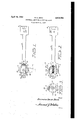
Figure 1 is a side elevational view of a wrench shank embodying this invention;
Figure 2 is a plan view of Figure 1; and
Figure 3 is an end view of Figure 2.
Similar reference characters refer to similar parts throughout the drawings.
In the construction indicated in the drawings, lll represents the shank extension of a wrench of conventional form. One end portionl I! is swaged out or enlarged and provided with a polygonal recess I2 into which the tongue of a preceding wrench shank (not shown) is inserted to operate it. The other end portion I 3 of the shank extension II! is also swaged out to form a bifurcated jaw internally arcuate and laterally open cn opposite sides to permit the insertions and rotation of an operable head I4 adaptable with a male end socket-engaging projection I5 for insertion in a socket to be rotated thereby. The head I4 has a rounded rib I'I straddled over its peripheral surface I8 and arranged to t at its back and sides into an arcuate groove I 8 provided in "the shank I D. Thehead i4 has two sides 2l)l A-iiat and tted close against the inner side surfaces 2| of the jaw lwhich serve to restrain it from turning inside the jaw, The jaw I3 however holds it bodily and allows it to rotate when the shank extension is turned. A passage 22 runs transversely through the jaw sides and aligns with a passage 23 in the head I4 so that a pin 26 of cylindrical contour may be passed through both to hold them together as a unit. The projection I5 has a conventional ball lock 24 arranged to secure it to the socket of the extension that the projection may be attached to at the time. Likewise a ball lock 25 is provided in the recess I2 for a similar purpose.
The removal of the head is readily performed by removing the pin 26 and withdrawing the operable head E4 from between sides 2l of the jaw I3. The rib Il, which is preferably knurled, facilitates this operation, as it enables the head to be readily grasped between the fingers of the operator. The head may be rotated on the pin 26 through an arc as long as that of the rib I1 and at the same time be substantially held within the jaw I3. This jaw also distributes the stresses exerted on the head to the shank proper and relieves the sides 2| and pin 26 from having to take care of all the torsional pressure placed upon it.
The knurling on the rib I1 does not interfere with the rotation of the head I4 in the groove I9 as there is suiilcient clearance to permit this. A ball lock 34 fits into indentations 35 in rib I'I. The pin 26 holds the head properly positioned in the jaw I3 to provide the clearance at the groove I9.
While but one general form of the invention is shown in the drawings and described in the specications, it is not desired to limit this application for patent to this particular form or in any other way otherwise than limited by the scope thereof, as it is appreciated that other forms of construction could be made that would use the same principles and come within the scope of the appended claims:
Having thus described the invention; what is claimed is:
l. A hinged joint comprising a shank having an enlarged end portion provided with a U-shaped slot forming spaced ears having confronting parallelsurfaces, said surfaces merging into a transverse-surface of said shank and forming the bot- Y torn of said U-shaped slot, said transverse surface being transverselyconcave, axially aligned pivot means provided in said ears, an arcuate transversely extending slot formed in said concave sur- .face, said arcuate slot and said concave surface having a curved peripheral surface complementary to the concave surface of said shank and to said-rib and arcuate slot being complementary in cross-sectional size to thereby prevent excessive torsional strain on said pivot means.
2. In the hinged joint described in claim 1,
spaced indentations provided in said rib, and a ball lock positioned in said arcuate slot to engage a selected indentation to frictionally hold said head member in a selected position.
RAYMOND DALEY BOYD.
REFERENCES CITED The following references are of record in the file of this patent:
UNITED STATES PATENTS Numb er Name Date 952,435 Miller Mar. 15, 1910 1,448,962 Hughes Mar. 20, 1923 2,294,510 Nakano Sept. 1, 1942
Priority Applications (1)
| Application Number | Priority Date | Filing Date | Title |
|---|---|---|---|
| US733895A US2504796A (en) | 1947-03-11 | 1947-03-11 | Adjustable-angle pivot-typerod joint |
Applications Claiming Priority (1)
| Application Number | Priority Date | Filing Date | Title |
|---|---|---|---|
| US733895A US2504796A (en) | 1947-03-11 | 1947-03-11 | Adjustable-angle pivot-typerod joint |
Publications (1)
| Publication Number | Publication Date |
|---|---|
| US2504796A true US2504796A (en) | 1950-04-18 |
Family
ID=24949550
Family Applications (1)
| Application Number | Title | Priority Date | Filing Date |
|---|---|---|---|
| US733895A Expired - Lifetime US2504796A (en) | 1947-03-11 | 1947-03-11 | Adjustable-angle pivot-typerod joint |
Country Status (1)
| Country | Link |
|---|---|
| US (1) | US2504796A (en) |
Cited By (5)
| Publication number | Priority date | Publication date | Assignee | Title |
|---|---|---|---|---|
| US2606389A (en) * | 1949-10-22 | 1952-08-12 | Edward C Fortmann | Fish lure |
| US7246544B1 (en) * | 2006-06-14 | 2007-07-24 | Chang Chuan Lee | Rotary wrench |
| US9808917B1 (en) * | 2016-09-03 | 2017-11-07 | Yih Cheng Factory Co., Ltd. | Ratchet wrench capable of rotating quickly and driving rotation |
| US20170361434A1 (en) * | 2016-06-17 | 2017-12-21 | Yih Cheng Factory Co., Ltd. | Ratchet wrench having positioning mechanism |
| US20170361435A1 (en) * | 2016-06-17 | 2017-12-21 | Yih Cheng Factory Co., Ltd. | Ratchet wrench having flexible positoning structure |
Citations (3)
| Publication number | Priority date | Publication date | Assignee | Title |
|---|---|---|---|---|
| US952435A (en) * | 1909-03-20 | 1910-03-15 | C M B Wrench Company | Socket-wrench. |
| US1448962A (en) * | 1921-11-26 | 1923-03-20 | Hughes William | Wrench |
| US2294510A (en) * | 1940-05-29 | 1942-09-01 | Nakano Rikio | Hinged ratchet wrench |
-
1947
- 1947-03-11 US US733895A patent/US2504796A/en not_active Expired - Lifetime
Patent Citations (3)
| Publication number | Priority date | Publication date | Assignee | Title |
|---|---|---|---|---|
| US952435A (en) * | 1909-03-20 | 1910-03-15 | C M B Wrench Company | Socket-wrench. |
| US1448962A (en) * | 1921-11-26 | 1923-03-20 | Hughes William | Wrench |
| US2294510A (en) * | 1940-05-29 | 1942-09-01 | Nakano Rikio | Hinged ratchet wrench |
Cited By (8)
| Publication number | Priority date | Publication date | Assignee | Title |
|---|---|---|---|---|
| US2606389A (en) * | 1949-10-22 | 1952-08-12 | Edward C Fortmann | Fish lure |
| US7246544B1 (en) * | 2006-06-14 | 2007-07-24 | Chang Chuan Lee | Rotary wrench |
| US20170361434A1 (en) * | 2016-06-17 | 2017-12-21 | Yih Cheng Factory Co., Ltd. | Ratchet wrench having positioning mechanism |
| US20170361435A1 (en) * | 2016-06-17 | 2017-12-21 | Yih Cheng Factory Co., Ltd. | Ratchet wrench having flexible positoning structure |
| US10131038B2 (en) * | 2016-06-17 | 2018-11-20 | Yih Cheng Factory Co., Ltd. | Ratchet wrench having flexible positioning structure |
| US9808917B1 (en) * | 2016-09-03 | 2017-11-07 | Yih Cheng Factory Co., Ltd. | Ratchet wrench capable of rotating quickly and driving rotation |
| US20180065234A1 (en) * | 2016-09-03 | 2018-03-08 | Yih Cheng Factory Co., Ltd. | Ratchet wrench capable of rotating quickly and driving rotation |
| US10717174B2 (en) * | 2016-09-03 | 2020-07-21 | Yih Cheng Factory Co., Ltd. | Ratchet wrench capable of rotating quickly and driving rotation |
Similar Documents
| Publication | Publication Date | Title |
|---|---|---|
| US4000767A (en) | Leverage screwdriver | |
| US3039340A (en) | Detachable connection for wrench heads | |
| US4442559A (en) | Utility knife | |
| US5943922A (en) | Chuck for threaded fasteners | |
| US2652735A (en) | Open-end wrench | |
| JP2664052B2 (en) | Tightening pin for tool holder | |
| US3091474A (en) | Chuck for drive shafts | |
| US4779494A (en) | Screwdriver having screw gripping feature | |
| US2504796A (en) | Adjustable-angle pivot-typerod joint | |
| US6016723A (en) | Ratcheting adjustable wrench | |
| US2445946A (en) | Terminal and clamp therefor | |
| US2722148A (en) | Fastening holder and starter with resilient arms | |
| US2600617A (en) | Adjustable crowfoot wrench | |
| US2697372A (en) | Slidable jaw insert for crescent head wrenches | |
| US4255990A (en) | Ratchet-action end wrench without ratchet | |
| US2546287A (en) | Wrench having pivoted outer jaw provided with guide slot for handle-jaw extension | |
| US2470865A (en) | Toolhead retainer | |
| US2566683A (en) | Screw-holding screw driver | |
| US2519073A (en) | Overload yielding wrench with ratcheting jaws | |
| US3216471A (en) | Tool holder | |
| US3094020A (en) | Bolt holding tool | |
| US3008723A (en) | Tool-holding handle | |
| US749134A (en) | Noah charles hyman | |
| US2474402A (en) | Ratchet means | |
| US2210605A (en) | Tool holder |